Transcription
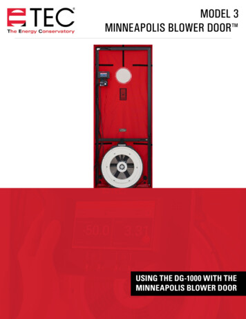
MODEL 3MINNEAPOLIS BLOWER DOOR USING THE DG-1000 WITH THEMINNEAPOLIS BLOWER DOOR
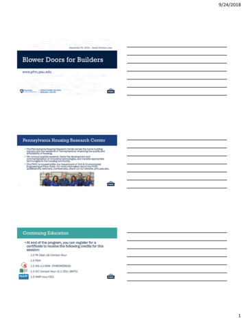
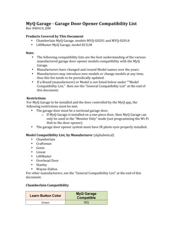
USING THE DG-1000 WITH THE MINNEAPOLIS BLOWER DOORCONDUCTING A ONE-POINT DEPRESSURIZATION TESTBefore the Test Install the blower door frame, panel and fan into an exterior doorway. For instructions about how to do this, please seeChapter 2 of the Minneapolis Blower Door User Manual. Prepare the building for the blower door test. For instructions about how to do this, please seeChapter 3 of the Minneapolis Blower Door Manual.Tubing Hookup1. Attach one end of the green tube to the Channel A reference tap. Run the otherend of the tubing outside through one of the holes provided in the lower cornerof the nylon panel and away from the flow of the fan.2. Attach one end of the red tube to the Channel B input tap. Attach the other endof the red tube to the pressure tap on the blower door fan.Note: For help with how to connect the tubing to the DG-1000, please use the Tubing Assistant on our website.Conducting the Test1. Turn on the DG-1000 gauge by pressing and holding the power button for a few secondsPower button2. After the Home screen loads, touch Gauge to open the Gauge app3. Touch the mode area to open the Channel B Settings menu. Select Flow @50. Touch device and then select Model 3 Fan. Touchthe arrow in the upper left of the screen to return to the Gauge app screen.ModeFlow @50Model 3 FanNote: In this specialized test mode, Channel A measures building pressure while Channel B displays the estimated buildingleakage at a test pressure of 50 Pascals (CFM50). The leakage estimate shown on Channel B is determined by mathematicallyadjusting the actual air flow from the blower door fan to a test pressure of 50 Pascals, using the real-time Channel A buildingpressure reading and a Can’t Reach 50 factor, which can be found in the Blower Door Manual on page 9.2
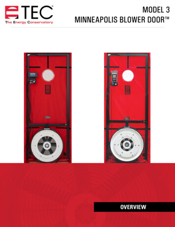
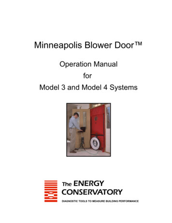
USING THE DG-1000 WITH THE MINNEAPOLIS BLOWER DOOR4. With the fan inlet still covered, touch Set Baseline to initiate the building baselinemeasurement procedure on Channel A.Set baseline5. During a baseline measurement, Channel A will display a long-term averagebaseline pressure reading while Channel B is used as a timer in seconds toshow the elapsed measurement time. When you are satisfied with the baselinemeasurement, touch enter and enter the baseline reading into the gauge.6. Channel A will now display the baseline adjusted building pressure value.7. Remove the No-Flow Plate from the Blower Door fan and install the flow ringwhich you think best matches the needed fan flow (see table below.)(Optional)(Optional)(Optional)8. Check (and adjust if necessary) the selected test device (i.e. fan) and configuration (i.e. flow ring) shown in the Gauge app tomatch the fan and flow ring being used in the test.9. Turn on the blower door fan.Using Cruise Control1. Turn the blower door speed control knob to the “just on” position (the controller ison but turned all the way down).2. Set the cruise target by touching the Cruise menu and selecting 50 Pa.Note: The fan control cable must be connected to the DG-1000 and the fan speedcontroller for this feature to work.3
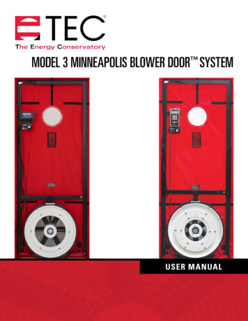
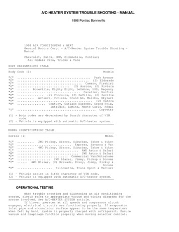
USING THE DG-1000 WITH THE MINNEAPOLIS BLOWER DOOR3. Touch the green play icon to start cruise. Once cruise is started, the fan speed slider will move on it’s own. The green playicon will change to an X, and a red stop icon will appear in the lower right of the screen. A pop-up will appear at the bottom ofthe screen to indicate that cruise has started.Start cruiseCruising screenCruise started4. The blower door fan will now slowly increase speed until the building depressurization displayed on Channel A isapproximately –50 Pa.5. Cruise will turn off when the X is touched, but the fan will continue running. When the X is touched, a pop-up will appear at thebottom of the screen that says “Cruise canceled.” Touch the red stop icon in the bottom right corner of the screen to stop the fan.When the fan is stopped a pop-up will appear at the bottom of the screen that says “fan stopped.”Cruise canceledFan stopped5.1 Controlling the Fan with the Gauge appTouch and slide the dot on the fan speed slider in the Gauge app to adjust the fanspeed using the DG-1000. As the fan speed increases, the building depressurizationdisplayed on Channel A should also increase. Continue to increase the fan speed untilthe building depressurization shown on Channel A is between –45 and –55 Pa.4
USING THE DG-1000 WITH THE MINNEAPOLIS BLOWER DOOR5.2 Manually Controlling the FanGradually increase the fan speed by slowly turning the fan controller clockwise. Asthe fan speed increases, the building depressurization displayed on Channel A shouldalso increase. Continue to increase the fan speed until the building depressurizationshown on Channel A is between –45 and –55 Pa.6. Channel B will display the one-point 50 Pa leakage estimate. Record this number.If the leakage estimate is fluctuating more than desired, try changing the timeaverage setting on the gauge by touching the Time Average menu and choosingthe 5 or 10 second or long-term averaging period.7.Turn off the blower door fan. If you are using cruise control, this is done by touching the red stop icon in the Gauge app.8. “-----” or “LOW” appearing on Channel B Whenever “-----” or “LOW” appears on Channel B in the Flow @ 50 mode, the gauge can not calculate a reliable leakageestimate. The messages “-----” and “LOW” appear on Channel B under the following conditions:»» “-----” is continuously displayed when the building test pressure from Channel A is below a minimum value of 10 Pa.Estimating building leakage results when the test pressure is below this value may result in large errors. If possible,install a larger flow ring or remove the flow rings to generate more fan flow. Be sure the fan is off when changingflow rings.»» Channel B reads “LOW” is continuously or LOW alternates with a flow reading when the air flow reading throughthe device is unreliable (i.e. you are trying to measure a flow outside of the calibrated range of the test device inits current configuration). If possible, you should change the test device configuration to match the flow rate beingmeasured (e.g. install a flow ring or a smaller flow ring). Be sure the fan is off when changing flow rings.5
USING THE DG-1000 WITH THE MINNEAPOLIS BLOWER DOORCONDUCTING A ONE-POINT PRESSURIZATION TESTBefore the Test Install the blower door frame, panel and fan into an exterior doorway. For instructions about how to do this, please seeChapter 2 of the Minneapolis Blower Door User Manual. Prepare the building for the blower door test. For instructions about how to do this, please seeChapter 3 of the Minneapolis Blower Door Manual.Tubing Hookup1. Attach one end of the red tube to the Channel B input tap. Attach the other endof the red tube to the pressure tap on the blower door fan.2. Attach one end of the green tube to the Channel A reference tap. Run the otherend of the tubing outside through one of the holes provided in the lower cornerof the nylon panel.3. Attach one end of the clear tube to the Channel B reference tap. Run the other end of the tubing outside through one of theholes provided in the lower corner of the nylon panel. The end of the clear tubing should be placed next to the side of the fan,but not in the fan’s airstream.Note: For help with how to connect the tubing to the DG-1000, please use the Tubing Assistant on our website.Fan DirectionBefore conducting the pressurization test, make sure the fan direction is reversed byremoving the fan from the nylon panel, and re-inserting it with the exhaust side facinginside the building.Conducting the TestOnce the equipment has been setup, follow the instructions in the depressurization test section of this guide (page 2).6
USING THE DG-1000 WITH THE MINNEAPOLIS BLOWER DOORSoftware InformationThe Energy Conservatory (TEC) offers a variety of Windows-based programs. These programs can be found and downloaded for freeat software.energyconservatory.com.TEC also offers driver support for the DG-500, DG-700 and DG-1000. The drivers are designed to work with Windows-basedcomputers with the following operating systems: Windows 7 Windows 8 Windows 8.1 Windows 10The drivers are available through Windows Update, and the DG-500 and DG-700 drivers can be downloaded from TEC atsoftware.energyconservatory.com.TEC also offers mobile apps for Apple and Android devices that can be found in the Apple App Store or the Google Play Store.Instructional VideosThe Energy Conservatory (TEC) offers a variety of online instructional videos, including Minneapolis Blower Door Quick Guide Minneapolis Duct Blaster Quick Guide Field Calibration Checks for Gauges Pressure and Airflow Basics Exhaust Fan Flow Meter TECLOG3 TECTITE 4.0 And many moreVisit www.YouTube.com/EnergyConservatory to see all of TEC’s instructional videos.More Blower Door GuidesAll blower door guides are available online at energyconservatory.com/blowerdoorguidesPlease refer to the guides listed below for further instructions. Minneapolis Blower Door Overview Using the DG-700 with the Minneapolis Blower Door Minneapolis Blower Door Manual Test Results and Sample Test Forms2801 21st Avenue SouthSuite 160Minneapolis, Minnesota 55407 2017 The Energy ConservatoryUpdated Aug 2017, V1Phone: (612) 827-1117Fax: (612) ory.com
USING THE DG-1000 WITH THE MINNEAPOLIS BLOWER DOOR Before the Test Install the blower door frame, panel and fan into an exterior doorway. For instructions about how to do this, please see Chapter 2 of the Minneapolis Blower Door User Manual. Prepare the building for the blower door test. For instructions about how to do this, please see .