Transcription
INSTALLATION INSTRUCTIONSAmarr Residential Steel Garage DoorsEntrematic manufactures & distributes garage doorsunder several brand names and trademarks, such as:Amarr , Heritage , Classica , Stratford , Oak Summit and other consumer brands and product names.165 Carriage Court, Winston Salem, NC 27105For replacement documents, parts, or quesƟonsabout installaƟon, call 1-800-503- DOORHours of OperaƟon:Monday - Friday 7am to 7pm Central TimeSaturday 8am to 4:30pm Central TimeTable of ContentsPage 1 - Table of ContentsPage 2 - Safety InformaƟon and WarningsPage 3 - Safety InformaƟon and Warnings (conƟnued)www.amarr.comPage 4 - Parts Index and QuanƟƟesInstaller: AŌer installaƟon iscomplete, aƩach all warninglabels, and tags where indicated and place this manualnear the door.Page 5 - Parts Index and QuanƟƟes (conƟnued)Page 6 - Preparing the Jamb and Spring Pad / Parts RequiredPage 7 - Installing Hardware on the SecƟonsPage 8 - Stacking SecƟons in the Opening / Installing VerƟcal TrackPage 9 - Stacking SecƟons (conƟnued)Page 10 - Stacking the Top SecƟon / Installing StrutsDate of installaƟon:Page 11 - Garage Door Opener Bracket - Required for Triple Layer DoorsPage 12 - Strut InformaƟon and installaƟonPage 13 - Installing the Horizontal Track and CompleƟng the InstallaƟonInstalled by:Page 14 - Track Hanger InstallaƟon (track parallel to joists)Page 15 - Track Hanger InstallaƟon (track perpendicular to joists)Page 16 - Torsion Spring InstallaƟonPage 17 - Slide Lock InstallaƟon (not to be used with electric opener)Page 18 - Perimeter Seal / Stop MoldingNotes:Page 19 - Low Head Room Torsion to the Front InstallaƟonPage 20 - Low Head Room Torsion to the Rear InstallaƟonPage 21 - Extension Spring InstallaƟon - Standard LiŌPage 22 - Extension Spring InstallaƟon - Low Head RoomREAD THE ENTIRE INSTRUCTIONS BEFORE USING THIS PRODUCT. FAILURE TO FOLLOW THE INSTRUCTIONS ANDSAFETY PRECAUTIONS IN THIS DOCUMENT CAN RESULT IN SERIOUS INJURY OR DEATH. KEEP THE INSTRUCTIONS INA SAFE LOCATION FOR FUTURE REFERENCE. ALSO READ THE OWNERS MANUAL (PROVIDED SEPARATELY).InstallaƟon InstrucƟons are available at no charge from Amarr, call toll free 1.800.503.DOOR,email:ask@amarr.com, or online at www.amarr.com. AGD Rev A 6/7/14FORM #99295090PRINTED IN USATable ofContents1
Overview of Safety Guidelines and Your ResponsibiliƟes:1. Overhead garage doors are large, heavy objects that move with the help of springs under high tensionand electric motors. Since moving objects, springs under tension, and electric motors can cause injuries,your safety and the safety of others depend on you thoroughly reading and understanding these instrucƟons and the owners manual (provided separately). If you have quesƟons or do not understand the informaƟon presented, call 1.800.503.DOOR.2. Most garage door incidents are caused by failure to observe basic safety rules or precauƟons. An incidentcan oŌen be avoided by recognizing potenƟally hazardous situaƟon before an incident occurs. A personmust be alert to potenƟal hazards. This person should also have the necessary training, skills andtools to install the door properly.3. This is the safety alert symbol. It is used to alert you to potenƟal personal injury hazards.The meaning of this safety alert symbol is as follows: AƩenƟon! Become Alert! Your Safetymay be at Risk. The message that appears under the warning explains the hazard and canbe either wriƩen or pictorially presented.4. Obey all safety messages that follow the Safety Alert symbol to avoid possible personal injury or death.The hazards are idenƟfied by the “Safety Alert Symbol” and followed by a “signal word” such as“WARNING” or “CAUTION”. For your convenience, the signal words and definiƟons are provided below: WARNING: Indicates a hazardous situaƟon which, if notavoided, could result in death or serious bodily injury.WARNING CAUTION: Indicates a hazardous situaƟon which, if notavoided, could result in minor or moderate bodily injury.CAUTION NOTICE: Indicates a situaƟon that could result in equipment relateddamage.NOTICE Safety Symbols – The following safety symbols appear throughout this manualto alert you to important safety hazards and precauƟons to prevent injury.WEAR SAFETYGLASSESOVERHEAD CRUSHHAZARDREAD THISMANUALWEAR HARD HATPROHIBITIONWEAR GLOVES5. Every possible circumstance that might involve a potenƟal hazard cannot be anƟcipated. The warnings inthis publicaƟon and on the product are, therefore, not all inclusive. If a tool, procedure, work method oroperaƟng technique that is not specifically recommended by EntremaƟc is used, you are responsibleSafetythat it is safe for you and for others. You are responsible that the product will not be damaged orInformaƟonbe made unsafe by the operaƟon, lubricaƟon, maintenance or repair procedures that you choose.2
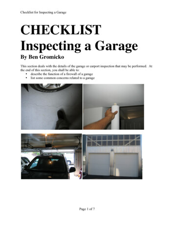
General Safety Guidelines: DO NOT permit children to operate the garage dooror door controls. Severe or fatal injury could resultshould a child become entrapped between thedoor and the floor. DO NOT a empt to adjust, repair or alter any partof the garage door, especially to springs, spring brackets,bo om corner brackets, fasteners, counterbalance licables or supports. Installa on and repair work MUSTbe performed by a trained garage door technician. RED fasteners must be used where required.These fasteners hold parts which are under extremetension. RED fasteners are not to be loosened or removed. DO NOT stand or walk under a moving garage door.Keep door fully in view and free of obstruc ons whenopera ng. DO NOT place fingers or hands into open sec onjoints or track when garage door is moving. REMOVE pull down ropes and disable locks onelectrically operated garage doors. ALWAYS wear work gloves and safety glasses duringinstalla on. INSPECT doors and hardware monthly for worn andor broken parts. TEST electric garage door opener’s safety featuresmonthly, according to manufacturer’s instruc ons. DO NOT hang tools or materials from horizontaltracks. DO NOT install the garage door on windy days.Garage door could fall during the installa on causingsevere or fatal injury. This garage door MAY NOT meet the building codewind load requirements in your area. Contact yourlocal building official for wind load code requirementsand building permit informa on. WARNING LABELS are important parts of the garage door(s). Place warning labels as indicated to the right, so that theyare not obstructed and can be easily read. DO NOT remove, cover or paint over the labels. Users shouldinspect labels periodically for legibility and should order (free of charge)replacement labels from Amarr, as needed.Please call toll free 1.800.503.DOOR or email ask@amarr.com.1. Spring Warning LabelNOTICEThe following four warning labels should be present3. Wall Warning Labelon or around garage door assemblies:for Door Opener1. Spring Warning Label, a ached to the spring assembly;2. General Warning Label, a ached to the back of the garage door panel;3. Warning Label for Garage Door Opener (provided separately with opener) 2. General Warning Labela ached to the wall in the vicinity of the wall control bu on, and;4. Bo om Bracket Tension Warning Label, a ached above the garagedoor’s bo om brackets.4. BoƩom BracketTension Warning LabelSafetyInformaƟon3
Fasteners (Actual Size) Minimum QuanƟty Required1/4 x 5/8 UNIVERSAL SCREWS3 SecƟonGarage Door4 SecƟonGarage Door5 SecƟonGarage DoorCenter SƟles12312341234# Fasteners34427046588013058741001544441/4" x 5/8" TRACK SPLICE BOLTS8881/4" x 20 SERR. WASHER HEAD NUTS1010103/8" - 16 Hex Nut6663/8" - 16 RED Hex Nut2222221212122222222221/4 x 3/4 UNIVERSAL SCREWS (RED - TEK)3/8" x 3/4" LSC BOLTS5/16" x 1 5/8" LAG BOLTS5/16" x 1 5/8" LAG BOLTS (RED)1-5/8”2-1/2”1/4"-20 x 2-1/2" Low Shoulder Carriage Bolt1/4"-20 x 1-5/8” (for 1-3/8” thick doors)Low Shoulder Carriage Bolt3/8" x 1 1/2" MACHINE BOLTSNOTICEA Windload specific drawing will accompany yourgarage door showing where the extra parts are located.RequiredParts4
Minimum Hardware RequiredUp to 8’ Tall(Not Actual Size)(Hardware for Torsion Spring Only)End Hinge(Right Shown)Rollers(Yours may appear different)Addi onal Hardware Required345Sec onGarage DoorsSec onGarage DoorsSec onGarage DoorsTwo Le&Two RightThree Le&Three RightFour Le&Four Right81012For Torsion Spring Low Head Room Front Mount(Not Actual Size)MinimumRequiredLow Head RoomTop Fixture2Addi onal Hardware RequiredJamb Brackets444For Torsion Spring Low Head Room Rear MountMinimumRequired(Not Actual Size)Center Bearing Plate111Low Head RoomTop Fixture2Torsion CablesOne PairOne PairOne PairEnd Bearing PlateOne Le&One RightOne Le&One RightOne Le&One RightEnd Bearing Plate2Cable DrumsOne Le&One RightOne Le&One RightOne Le&One RightOutside Hook-UpBo om Fixture1 Le&1 RightTop Fixture222Addi onal Hardware RequiredFor Standard LiŌ, Extension Spring DoorsLi HandleRoller m (2) Required(to be assembled)One Le&One RightOne Le&One RightCenter HingeMinimum2Minimum3Minimum4S le S ffenerHinge Hole PlugMinimum1Minimum1Minimum1Minimum1Nylon Bearing111Flag BracketOne Le&One RightOne Le&One RightOne Le&One um1Minimum2 EachMinimum2 EachMinimum2 EachEnd S le Slide LockTorsion SpringYellow Red BlackMinimum1Li Handle / Step PlateTube SpacersMinimumRequired1 BagAddi onal Hardware RequiredFor Low Head Room, Extension Spring Doors* Extension SpringMinimum1(Not Actual Size)These Parts Replace ItemsExtension Spring Parts BagIncluding:(4) Pulleys(2) Sheave Forks(2) Cable Adjustment Clips(2) “S” Hooks(2) Eye Bolts(2) Li / (2) Safety Cables(4) 5/16 x 18 RED Hex Nuts(4) 3/8 x 16 RED Hex Nuts8One Le&One RightBo om Fixture* Extension SpringMinimum (2) Required(Not Actual Size)These Parts ReplaceItemsMinimumRequiredLow Head RoomTop Fixture2Outside Hook-UpBo om Fixture1 Le&1 RightExtension Spring Parts BagIncluding:(4) Pulleys(2) Sheave Forks(2) Cable Adjustment Clips(2) “S” Hooks(2) Eye Bolts(2) Li / (2) Safety Cables(4) 5/16 x 18 RED Hex Nuts(4) 3/8 x 16 RED Hex NutsNOTICEYour door kit may contain more partsthan shown here. These are theminimum parts required for mostsingle car garage door installaƟons.1 BagRequiredParts5
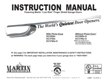
Figure 2Tools Required for InstallaƟon:Perimeter Seal / Aluminum BradsOperator Bracket (if using operator)Track Hanger Angle / AddiƟonal Lag ScrewsWinding Bars (for Torsion Spring / Purchasefrom Amarr)16-Penny NailsHeadroomRequired(page 6,Table 1)WARNING - Strike Hazard1 12 “diameterholes to bepredrilled1 12 “1 12 “1 12 “Not Included/Purchase Separately:WARNINGSPRING PAD3“(4) 16Six Foot (6') Step LadderLevel 24" or 48"Claw HammerLock Grip Pliers or C clampsSocket WrenchSockets: 3/8", 7/16" and 9/16"Wrenches: 3/8", 7/16" and 9/16"Electric DrillDrill Bits: 3/32", 3/16", 1/4", and 3/8”ChalkTape MeasureSaw Horses - with padded top surfaces(2) Needed for garage doors up to 9’ wide(3) Needed for garage doors wider than 9’The jamb and spring pad MUST be securelyanchored to the wall. Failure to secure thejamb or spring pad could result in death orserious bodily injury.AƩach ONLY to #2 Southern Yellow Pine (orbeƩer). DO NOT use nails to secure the trackor spring pad.*See Dasma TDS-161 (www.dasma.com)SPRING PAD REQUIREMENTS:*Minimum 2”x 6” Southern Yellow Pine, Grade #2 or beƩer.*Spring Pad should span from the header to height of ceiling .*Pre-drill (4) 3/16” diameter holes, no closer than 1-1/2” from any edge.*Secure Spring Pad with (4) 5/16”x 4” lag screws (not included).*DO NOT aƩach directly to drywall or sheetrock.EqualDistanceEqualDistanceMin. 2"x 6"Jamb(Header)2"x 6"Pad R SpringeT o r s i quired foron SprinElectric Op gs oreratorMin. 2"x 6"JambJamb fastenersflush with surfaceNo closer than1 1/2” to any edgeto prevent the woodfrom spliƫng.LevelDoor Width Opening WidthPerimeterSealDoor Height Opening HeightPlumbPerimeterSealPerimeterSealSide Room5-1/2” Min.Jamb &Spring PadFigure 111-1/2” Min.Center Post(Two Doors Side by Side)6
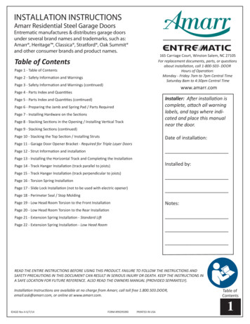
Step 1: Framing the OpeningThe garage door (rough) opening should be approximatelythe same size as the door (Figure 1, page 6). The openingmust be framed with 2” x 6” minimum, wood jambs.Torsion Spring and Opener applicaƟons require 2“ x 6”minimum Spring Anchor Pads (see Figure 2, page 6). Thejambs must be plumb and the header level for a squareopening. The jambs should extend to the same height asthe headroom required (Table 1). All jamb fasteners shouldbe flush with the jambs and securely anchored to the wall.Table 1 - Headroom ChartType of Track Min. HeadroomSpring 5"12"15"Table 2 - Door Height ConfiguraƟonMin. HeadroomReq’d w/ Opener18"15"18"15"18"12"15"12"15"Step 3: Sec on Selec onCheck the secƟon height chart (Table 2) to ensure properquanƟty of secƟons. The boƩom secƟon has a rubberweather seal on the boƩom. The inside of the secƟonshave pre-drilled holes for most fasteners.Note: If struts are supplied with your door, refer to page 12for proper placement, and Page 10, Step 22 (A or B) forstrut installaƟon instrucƟons.Step 4: Safety Bo om Bracket Installa onLocate the Safety BoƩom Bracket assembly (Figure 3).Separate all four parts by snapping apart (Figure 4). Placethe boƩom secƟon face down on a sturdy pair of paddedsaw horses (Figure 5). AƩach the leŌ BoƩom Bracket Baseto the boƩom of the leŌ end sƟle (Figure 5A) aligning withholes #20 & #23 (#15 & #18 on Triple Layer doors). Fastenthe base with (2) 1/4” x 5/8” RED Universal Screws. Alignthe BoƩom Bracket Roller Carrier with the matching holesin the base and aƩach with (2) 1/4” x 5/8” UniversalScrews. Insert the Roller into the BoƩom Bracket RollerCarrier (Figure 5G). Repeat this procedure for the right endsƟle.Note: Holes in the sƟles may not line up with all fixtures,handles, and locks. Use a 3/32” drill bit to start pilot holesfor fasteners where pre-drilled holes are not provided. Notall holes will be used.Note: For all Single & Double Layer doors use Yellow TubeSpacers.For 1-3/8” thick, Triple Layer doors use Black Tube Spacers.For 2” thick, Triple Layer doors use Red Tube Spacers.16'-3"328"And2And216'-9"6'-9"131And1Note: Marked L & RFor Right or LeŌSide Mount6'-10"17'-0"4Or37'-1"7'-4"1AndBoƩom BracketRoller Carrier7'-6"Figure 3122211257'-8"BoƩom BracketBase32"127'-9"418'-0"32Or3Note: It is important to know whichmodel you are installing, see examples below.Figure 4SINGLE LAYERSteel1000DOUBLE LAYERSteel InsulaƟon2000TRIPLE LAYERSteel InsulaƟon Steel3000Note: Your garage door may appear slightlydifferent, but installa on steps are the same.DFigure 5C2D*4 & 5 SecƟon garagedoors startwith #1HingePocketTriple LayerGarage Doors3 SecƟon garagedoors startwith #2Triple LayerGarage DoorsCenter StileNote: (3) SecƟon tall doors start with a #2 Roller Carrier.Step 8: Step Plate / Li Handle Installa onFor Single & Double Layer doors, drill two (2) 1/4” holesstraight through the Center SƟle and face of the door, usingpre punched holes U & W on the sƟles as a template on theboƩom end of the center sƟle (Figure 5E).For Triple Layer Doors, drill two (2) 1/4“ holes straightthrough the Center SƟle and face of the door, using the twodimples near the boƩom of the secƟon as a template. Thendrill (2) 3/8” holes through the inside skin only (to insertthe Tube Spacer).Install the Step Plate / Tube Spacers / LiŌ Handle (outside &inside) using (2) 1/4” - 20 x 2-1/2” Carriage Bolts and1/4”-20 Nuts (bolt heads should be on the outside) (onTriple Layer doors refer to Figure 5F*). Do not over-Ɵghten,you could crush the secƟon and the tube spacers.6'-2"21"2Step 6: Roller Carrier Installa onRoller carriers have a number stamped on them foridenƟficaƟon and their placement on the door is important(Figure 5C). All roller carriers are aƩached to the end sƟleswith (2) 1/4” x 5/8” Universal Screws, using holes #2 & #6(#4 & #8 on Triple Layer doors). Insert rollers as shown(Figure 5C). Start with Roller Carrier #1 for the boƩomsecƟon, then using #2, #3, #4 as required.Note: The words “THIS SIDE OUT” must be visible. Theactual hinge point or barrel of the hinge, must be inside ofthe hinge pocket.46'-6"Step 5: Li Cable Installa onSecure the liŌ cable to the boƩom bracket by hooking thelooped end of the cable over the liŌing stud (figure 5B). Iftwo sets of cables are supplied, use the longer cables as liŌcables.Step 7: Center Hinge Installa onLocate the Center Hinges, rotate and insert the hinge(s)into the hinge pocket(s) (Figure 5D). All Center Hinges areaƩached with (2) 1/4 x 5/8” Universal Screws using holes A& C (#4 & #6 on Triple Layer doors Figure 5D*).6'-0"6'-5"Note: Jamb and Spring Pad installaƟon is typicallyperformed by the builder (carpenter) of the home at theƟme of home construcƟon.Step 2: Perimeter Seal Installa onPerimeter Seal is to be purchased separately. It is notsupplied with your door, see Page 18 for details.SecƟon Height & QuanƟty(For doors over 8’ tall,contact Amarr Garage Doors)DoorHeightTubeSpacersGAF*FETube Spacers(Yellow)REDFastenersLeŌ SideShownBWARNING RED fasteners must be used where required. These fasteners hold parts which are underextreme tension. RED fasteners are not to be loosened orremoved.InstallingHardware7
Step 9: Stacking the BoƩom SecƟon in the OpeningPlace the boƩom secƟon (with hardware installed) inthe opening against the Perimeter Seal and centeredfrom side to side (Figure 6). Place a level on the top ofthe secƟon (Figure 6A). If necessary, use a piece ofwood as a shim under the low side to make the secƟonlevel (Figure 6B).CPerimeter SealAStep 10: Securing the SecƟon in the OpeningTemporarily secure the secƟon in the opening bydriving a 16-penny nail into the jamb at each end ofthe secƟon and carefully bend it over the edge of thesecƟon to secure in place (Figure 6C). Make sure thesecƟon is securely held in place.BoƩomSteps 11-15: Track Assembly and AƩachmentWARNING High Spring Tension, Strike HazardThe track and spring pad are under high springtension and MUST be securely anchored. Failure to securethe track or pad could result in death or serious injury.Anchor into wood stud or structurally sound member. Forwood studs on top of masonry or steel jambs, use 1-3/4”lags. DO NOT use nails to secure the track or spring pad.*See Figure 2, page 6BShim Low Side(if required)Figure 6Notes:* Hand ghtening will allow for slight adjustmentsduring the installa on.Nut to outsideof trackT1JambBracketRight Side AssemblyShownAFlagBracketT1L* Be sure to predrill a 3/16” hole for lag bolts, toprevent spli ng of wood.* 1/4”-20 Hex Nuts always go on the outside of thetrack.* If you raise one side of the bo om sec on to level it,you MUST raise the track on that side the sameamount for the door to operate properly.Upper Jamb BracketLocaƟon6’ - 7’ Tall 7‘3”-8’ Tall@ 38” **Jamb Bracket AlignmentDoors2” 1-3/8“6’ - 7’ Tall 4/5 1/37‘3”-8’ Tall 4/6 1/438”@ 58” **Track Splice Bolts toAlign with Numbers onJamb Brackets*Measured from BoƩomto Middle of Slot* Ver cal Tracks must be level with each other for thedoor to func on properly. The bo om of the trackMUST be equal to the bo om of the sec on. If notlevel, raise the lower track but not higher than 3/8“from the floor (Figure 8D). Ver cal Tracks must beplumb as well.* Maintain 3/8” space between the door edge and thever cal track (Figure 8C).58”TT110”All DoorsTT1T5T LCTLeŌVerƟcalTrackRightTFigure 7BTStep 11: Jamb Bracket to Track AƩachment(Right Side)Align the lower Universal Jamb Bracket with the flatside of the track as shown in Figure 7A.AƩach with (1) 1/4” x 5/8” Track Splice Bolt and (1)1/4”-20 Hex Nut, through the oval holes. Hand Ɵghten.Repeat this step for the upper Jamb Bracket. See theJamb Bracket LocaƟon chart for placement (Figure 7).T9CANOTICEThis door MAY NOT meet the buildingcode wind load requirements in yourarea. Contact your local buiding officialfor wind load code requirements andbuilding permit informa on.BBStep 12: Flag Bracket AƩachment (Right Side)PosiƟon the Flag Bracket to the top of the track (Figure7C). Loosely aƩach the lower slot of the Flag Bracket tothe top of the VerƟcal Track with (2) 1/4” x 5/8” TrackSplice Bolts and (2) 1/4”-20 Hex Nuts and fingerƟghten.Step 13: PosiƟoning the Track on the Door (RightSide)Place the assembled VerƟcal Track with Jamb BracketsaƩached over the rollers as shown in Figure 8C & 8D.Step 14: MounƟng the VerƟcal Track to the Jamb(Right Side)With both tracks properly aligned, predrill 3/16” holesto prevent spliƫng of wood, and securely fasten eachJamb Bracket to the jamb with (1) 5/16”x1-5/8” LagBolt (Figure 8A).Step 15: MounƟng the Flag Bracket to the Jamb(Right Side)Predrill 3/16“ holes to prevent spliƫng of wood, andsecure the Flag Brackets (keeping them plumb) with(3) 5/16”x1-5/8 lag bolts to the jamb (Figure 8B).Repeat Steps 11 thru 15 for the leŌ side VerƟcalTrack.3/8”Right Side AssemblyShownD3/8” Max.AdjustmentFrom FloorAFigure 8StackingSecƟonsA8
Step 16: Installing Intermediate SecƟon HardwarePlace the second secƟon face down on the padded saw horses.Install the Roller Carriers and Rollers as shown on Page 7, Step 6.Figure 9Install the Center Hinge(s) as shown on Page 7, Step 7.Notes:* “Intermediate” refers to secƟons above the boƩom secƟon and below thetop secƟon. SecƟons are interchangeable (except for 3 secƟon doors whichneed correct placement to create the various designs).* If addiƟonal reinforcement (struts) are supplied or required with your door,refer to page 12, for proper locaƟon.* Begin with Page 10, Step 22 A or B for Strut InstallaƟon and PlacementinstrucƟons.Step 17: Stacking Intermediate SecƟon(s) in OpeningLiŌ the Intermediate SecƟon, with the rollers, roller carriers, center hinges,and struts (if installed). Slide the rollers down into the track (Figure 9). Lowerthe secƟon down onto the boƩom secƟon that you stacked earlier (Figure 10).Step 18: Finish Center Hinge(s) InstallaƟonOnce the secƟon is in place, rotate the upper half(s) of the Center Hinge(s) andaƩach to the secƟon above with (2) 1/4”x5/8” Universal Screws (Figure 11).Use holes V & W for single and double layer doors.Triple layer doors are not marked, but will line up with the holes in the CenterHinge.Step 19: End Hinge InstallaƟon (LeŌ & Right)Fit the End Hinges between the track and the secƟon. Align the End Hingestuds with the extruded holes in the edge of the end sƟles and insert. Securethe hinge with (2) 1/4”x5/8” Universal Screws (Figure 12).Use holes 19 & 23 for single and double layer doors.Use holes 14 & 18 for triple layer doors.IntermediateIf lock is required,install in this secƟonBoƩomFirmly hold the End Hinges in place with a screwdriver between the track andthe hinge, as you Ɵghten the screws (Figure 12).CAUTION Pinch and Strike Hazard. Secure the end hinge withappropriate universal screws (see figure 12). Failure to properly secure thehinge could result in minor or moderate bodily injury. Wear work gloves andsafety glasses.Note: Repeat steps 16-19 for each intermediate secƟon required(Figure 13).Figure 10Figure 11Use Screwdriver to hold End Hinge inplace as you Ɵghten screws.IntermediateFigure 12IntermediateBoƩomRRight side shownEnd Hinge StudThe End Hinge Stud is inserted into the extruded hole in the side of the lowersecƟon. (2) 1/4”-20 x5/8” Universal Screws fasten the End Hinge to the uppersecƟon.Figure 13StackingIntermediateSecƟons9
Step 20: Installing Top Sec on HardwarePlace the top sec on face down on your padded saw horses. Locatethe S le S ffener(s) or Hinge Hole Plugs.Note: For Single & Double Layer doors, S le S ffeners MUST beinstalled along the top edge of the top sec on in the center s lehinge pocket(s). If your door has mul ple center s les and Hinge HolePockets, there should be one in each pocket.Step 21: Installing the S le S ffener(s)(Single & Double Layer doors only)Posi on and rotate the S le S ffener(s) as shown in Figure 14A.When installed correctly they should appear flat as shown in Figure14B. S le S ffener(s) once installed, do not require any fasteners tosecure in posi on. The side tabs will maintain the part securely in thehinge pocket.ABCenter S leHinge PocketFigure 14CNote: If struts are not required, skip to Step 23.Step 22A: Strut Installa on - (Single & Double Layer doors Only)If Strut(s) are required, placem ent is shown on page 12. Install using(2) 1/4”x5/8” Universal Screws into each end and center s le (Figure15C).A ach Strut(s) to S le S ffener(s) and center s le(s) with (2)1/4”x5/8” Universal Screws, using the top and bo om holes (Figure15A).Step 22B: Strut Installa on - Triple Layer DoorsIf Strut(s) are required, placement is shown on page 12. Install using(2) 1/4”x5/8” Universal Screws into each end and center s le (Figure15C). Install the Hinge Hole plug as shown in Figure 15D.A ach Strut(s) to the center s le with (2) 1/4”x5/8” Universal screws,using the Strut Clip to fasten the Strut to the lower hole (Figure 15D).Note: Due to lack of available head room (refer to Page 7, Table 1),you may require a Low Head Room applica on. If this is the case, skipStep 23 and go to Step 24.Strut ClipADHinge Hole PlugCStep 23: Top Fixture Installa on (Standard Head Room)Align the Top Fixtures with holes 4,5,&9 (Figure 14C) on the ends les. Secure the fixture to the end s les with (3) 1/4” x 5/8”Universal Screws (Figure 14C). Insert Rollers as shown (Figure 14C).Leave the slide loose for adjustment later.Step 24: Top Fixture Installa on (Low Head Room)Align the Flat Top Fixture (for Low Head Room applica ons), withholes 1 & 4 (Figure 15B) on the top corner of the end s les. Securethe fixture to the end s les with (2) 1/4”x5/8” Universal Screws(Figure 15B). Insert Rollers as shown (Figure 15B). If a strut isrequired, refer to Step 22 for instruc ons. The Strut will mount on topof the lower por on of the Low Head Room Flat Top Fixture (Figure15B).BFigure 15Step 25: Stacking the Top Sec on in the OpeningLi the Top Sec on, with the rollers, top fixtures and struts (ifrequired). Lower the sec on on to the previously installedintermediate sec on. Temporarily secure the top sec on by driving a16-penny nail into the header and carefully bending it over (Figure16A).AStep 26: Center Hinge(s) Installa onOnce the top sec on is secured, rotate the upper half(s) of the CenterHinge(s) and a ach to the upper sec on with (2) 1/4“x5/8” UniversalScrews (Page 9, Step 11).TopStep 27: End Hinge Installa on (Le & Right)Fit the End Hinges between the track and the sec on. Align the EndHinge studs with the extruded holes in the edge of the end s les andinsert. Secure the hinge with (2) 1/4”x5/8” Universal Screws (Page 9,Step 19, Figure 12).Use holes 19 & 23 for single and double layer doors.Use holes 14 & 18 for triple layer doors.IntermediateFirmly hold the End Hinges in place with a screwdriver between thetrack and the hinge, as you ghten the screws (Page 9, Figure 12).CAUTION Pinch and Strike Hazard. Secure the end hingewith appropriate universal screws (see Page 9, figure 12). Failure toproperly secure the hinge could result in minor or moderate bodilyinjury. Wear work gloves and safety glasses.BCIntermediateBo omFigure 16StackingTop Sec onInstallingStruts10
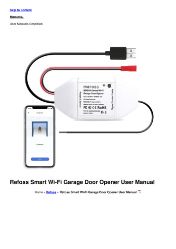
Garage Door Opener Bracket Installation(Required for Triple Layer Doors)WARNINGIf your door did not come with a strut,adding one will change the weight of your door. Theincreased weight may require using different springs thanthe ones supplied. Incorrect springs can lead to pre-maturefailure of the door. Check with your vendor beforeproceeding.Notes:* Triple layer doors require the Garage Door OpenerBracket shown to the right (Figure 1A). This bracket is notsupplied with your door and must be purchasedseparately.Figure 1Opener Bracket* Single and Double layer doors do not require thesesteps. Your Garage Door Opener will come with an easy toinstall bracket and instructions for installation.* All doors that use an ELECTRIC OPENER require aminimum of (1) strut mounted to the top section.* Before you proceed with Page 10, Step 22B of theInstallation Instructions, attach the Garage Door OpenerBracket to the section as shown (Figure 1).Step 1: Attach the strut to the top of the section followingthe instructions from Page 10, Step 22B. Before insertingthe (2) 1/4”x5/8” Universal Screws in to the middle of thestrut, the screws will now go through both the strut andthe Garage Door Opener Bracket (Figure 1 & 2). On thelower side of the strut, you will need to use a Strut Clip asshown in Figure 2A.Step 2: Install your top section as shown in the InstallationInstructions (page 10, Step 25-27).The Opener Bracket will mount on top of the CenterHinge, with (1) 1/4”x5/8” Universal Screw (Figure 3).AFigure 2BStep 3: Attach the Opener Arm to the pin (B) in Figure 2.For further information concerning installation of yourElectric Garage Door Opener,consult the manufacturer’s instructions.Figure 3OpenerBracket11
Step 1 of 3: Number of Struts & Strut SizeModelSingle Layer / Double LayerGarage DoorsDoor Width4 Sec ons5 Sec ons6'-0" - 14'-0"0 Struts0 Struts14'-2 - 16'-0"(1) 2” Strut(1) 2” Strut16'-2" - 18'-0"(3) 2” Struts(3) 2” Struts18'-2" - 20'-0"(4) 3” Struts(4) 3” StrutsELECTRIC OPENER ATTACHMENTWhen installing a garage door opener, the following applies:1. The garage door springs must be in good working order andthe door must be balanced (should be able to raise the door halfway and have the door stay in place).2. The top sec on of the garage door MUST include a strut (seePage 10, Step 22 A or B).3. Disconnect and/or remove all locks and pull ropes. A emp ngto use the opener while door is locked will damage your garagedoor. FAILURE TO DO SO WILL VOID DOOR WARRANTY.Minimum (1) strut required, on top sec on, for doors with openerModelTriple Layer Garage DoorsWidth4 Sec ons5 Sec ons6'-0" - 10'-0"0 Struts0 Struts10'-2" - 16'-0"(1) 2” Strut(2) 2” Strut16'-2" - 18'-0"(3) 2” Strut(4) 2” Struts18'-2" - 20'-0"(3) 2” Strut †(4) 2” StrutsMinimum (1) strut required, on top sec on, for garage doors with opener† Not Ava
2. General Warning Label, a ached to the back of the garage door panel; 3. Warning Label for Garage Door Opener (provided separately with opener) a ached to the wall in the vicinity of the wall control bu on, and; 4. Bo om Bracket Tension Warning Label, a ached above the garage door's bo om brackets. 2. General Warning Label 4.