Transcription
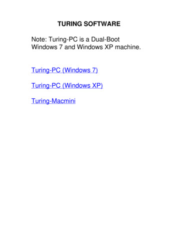
INSTRUCTION MANUALFeaturing Martin “Low Risk” Finger Shield Garage Doors.srenepOrooDtseteiuQs’dlroThe W With Photo EyesDC2500eDC3700eDC3700e-HWithout Photo Eyes*DC2500e-ODC3700e-Obe Ordered as a* MustUL Listed Martin GarageDoor and Opener System.See page 5 for IMPORTANT INSTALLATION, MAINTENANCE & SAFETY INSTRUCTIONS*WARNING! The back page helps you determine if your garage door is “HIGH RISK”.Martin Door Manufacturing Salt Lake City, Utah 84127-0437 USARMSTULRISO 9001RFIA8949TMINCREGMARTIDOOR OPENERSISO 9001QualityStandardEREDF.C.C.US CertifiedIndustryCanadaMARTIN DOOR MFG.www.martindoor.com Printed in the USACopyright 20074/2007 AD-IM09-11
OPTIONALPUNCHED ANGLE“C”BRACKETSMARTIN SIDE-MOUNT OPENER INSTALLATION- May be mounted right side or left side WARNING! For Martin Finger Shield Garage Door Systems only.POWERHEADCHASSISRAIL SUPPORT BRACKETRAIL ASSEMBLYOPENER HEADER BRACKETBELTPOWERHEADEND STOP WITH CLEVISPIN AND COTTER RINGLIGHTLENSTORSION TUBETROLLEY“L” STRUTTORSION SPRINGOPENER HEADERBRACKETEND STOP WITH CLEVISPIN AND COTTER RINGEMERGENCYRELEASECORDOPENER DOOR BRACKETTOP DOOR SECTIONEMERGENCYRELEASETAGSTRAIGHT AND CURVEDPOWER ARMKNOBWALLCONTROLORPUSHBUTTONOPENER DOOR BRACKET3/8” X 1” SHORT NECKCARRIAGE BOLT AND3/8” LOCK NUTOPENER POWER ARM MUST BE FASTENEDOUTSIDE THE OPENER DOOR BRACKET“L” STRUT3/8”x1”SHORTNECKCARRIAGEBOLTOPENER DOOR BRACKETOPENER DOOR BRACKET“L” STRUT (IF PROVIDED)3/8” X 1” SHORT NECKCARRIAGE BOLT AND2- 3/8” LOCK NUTS3/8” LOCK NUTSTOP ROLLER BRACKETTOP ROLLERBRACKETPHOTOEYETOP DOOR SECTIONCURVEDPOWER ARMENDSTILE2COPYRIGHT 2007 MARTIN DOOR
MARTIN CENTER-MOUNT OPENER INSTALLATION- May be mounted off-center for Martin Finger Shield Garage Door Systems only OPTIONAL“C”PUNCHED ANGLEBRACKETSPOWERHEADCHASSISRAIL SUPPORT BRACKETRAIL ASSEMBLYOPENER HEADER BRACKETPOWERHEADEND STOP WITH CLEVISPIN AND COTTER RINGBELTLIGHTLENSTROLLEY“L” STRUTTORSION TUBEEMERGENCYRELEASECORDTORSION SPRINGOPENER DOOR BRACKETEMERGENCYRELEASETAGKNOBTOP DOOR SECTIONSTRAIGHT AND CURVEDPOWER ARMWARNING AND SAFETY LABELWALLCONTROLORPUSHBUTTONPACKET FOR OWNERSDOOR AND OPENERINSTRUCTION MANUALSOPENER POWER ARM SHOULD BE FASTENED INSIDE THE OPENER DOOR BRACKET3/8”x1” SHORT NECKCARRIAGE BOLTOPENER DOOR BRACKETCURVEDPOWER ARM“L” STRUTCURVEDPOWERARMPHOTOEYE3/8” LOCK NUTSDRILL 1/8” (3) HOLE AND FASTEN OPENERCOPYRIGHT 2007 MARTIN DOORPHOTOEYEDOOR BRACKET TO “L” STRUT AND DOOR SECTION3
MARTIN GARAGE DOOR OPENER PACKAGE CONTENTS: 1 - POWER HEAD BOX, 1 - RAIL ASSEMBLY CTORIALDC2500eDC2500e-OH HEAVY DUTYO NO PHOTO EYES1- RAIL ASSEMBLY10’6” (3200) long Rail Assembly for doors up to 7’3” (2200) high11’6” (3500) long Rail Assembly for doors up to 8’3” (2500) high13’6” (4100) long Rail Assembly for doors up to 10’3” (3100) high15’6” (4700) long Rail Assembly for doors up to 12’0”(3700) high17’6” (5300) long Rail Assembly for doors up to 14’0”(4300) highMARTIN DC3700 GARAGE DOOR OPENER SYSTEMINSTRUCTIONMANUALM ARTI NDOOR OPENERSFor all Residential Garage Doors up to 12’ (3700) High.TM!RTINMAINSTRUCTIONMANUALM ARTI NDOOR OPENERSTM!1 OR 2 - 2 BUTTON MINITRANSMITTER W/ VISOR CLIPMartin Door Manufacturing Salt Lake City, Utah 84127-0437 U.S.Awww.martindoor.com Printed in the U.S.A. 20mCopyright 20018/2001AD-01IM-03Martin Door Manufacturing Salt Lake City, Utah 84127-0437 U.S.ATINMARINMART1 - RELEASE CORD1 - FULL SIZE INSTRUCTION MANUAL1 - MINI SIZE INSTRUCTION MANUAL(PLACE IN PLASTIC PACKET ONBACK OF MARTIN GARAGE DOOR)MARTIN DC3700 GARAGE DOOR OPENER SYSTEMFor all Residential Garage Doors up to 12’ (3700) High.MARTIN1- STRAIGHTPOWER ARMIN RAIL ASSEMBLY BOX / IN DOOR HARDWARE BOX FOR UL LISTED MARTIN GARAGE DOOR AND OPENER SYSTEMS.1 - POWER HEADIN POWER HEAD BOXDESCRIPTIONwww.martindoor.com Printed in the U.S.A. 20mCopyright 20018/2001AD-01IM-032 - WARNING LABELS4 BUTTON MINI TRANSMITTER IN POWER HEAD BOXWITH VISOR CLIP (OPTIONAL) OPTIONALACCESSORIES3 BUTTON MICROTRANSMITTER (OPTIONAL)1- OPENER DOOR BRACKETMOUNTING PLATE1- OPENER HEADER BRACKETMOUNTING PLATE(OPTIONAL)BATTERY(#Cr2032)1 - CURVED POWER ARM1 - PROGRAMMING TINEIN POWER HEAD BOXPhoto EyePhoto Eye CapFastenerSun ShieldMountingBracketPhoto Eye Cap FasteningWheelIN POWER HEAD BOXEXCEPT DC3700e-O / DC2500e-OMARTIN2 - PHOTO EYES W / WIRE2 - PHOTO EYES CAP FASTENERS2 - MOUNTING BRACKETS2 - PHOTO EYE CAPS2 - PHOTO EYE FASTENING WHEELS1 - PHOTO EYE SUN SHIELD20 - STAPLES4 - ROUND HEAD SCREWS4 - PLASTIC ANCHORS6 - CONCEALED PHOTO-EYEWIRE RIVETS (DC3700e ONLY)1 - RAIL SUPPORT BRACKET2 - FOR DC3700e - H OPENERSWIRELESS KEYLESSENTRY2 - “C” BRACKETSKEYSWITCH4 - 6 X 14 mm CHASSISSCREWS4 - 5/16” X 2” LAG SCREWSVAULTKEYRELEASE4 - 3/8 X 2“ PLASTIC ANCHORS1 - WALL CONTROL (DC3700e)OR PUSH BUTTON (DC2500e)9 - 3/8” X 1” CARRIAGE BOLTS10 - 3/8” LOCK NUTSORPush ButtonWall ControlIN POWER HEAD BOX42 - TAPERED HEAD SCREWS10 - STAPLES2 - PLASTIC ANCHORS1 - 30’ (9144) BUNDLE OF WIRE1 - CLEVIS PIN, COTTER RINGPOWERESERVEBATTERY BACKUPIN POWER HEAD BOX4 - 1/4” X 1” THREAD FORMINGSCREWSCOPYRIGHT 2007 MARTIN DOOR
!TO REDUCE THE RISK OF SEVERE INJURY ORDEATH, READ AND FOLLOW ALL INSTRUCTIONSDo not install this opener or any other opener on "HIGH RISK" garage doors that may cause severe injury, entrapment or death!See back page for serious injuries which may occur if “HIGH RISK” areas are left uncorrected. Martin Garage Doors are “Low Risk”.IMPORTANT INSTALLATION, MAINTENANCE & SAFETY INSTRUCTIONSUntrained or Negligent Installing, Adjusting and Servicing can be Dangerous! Thegarage door springs and related parts can cause serious injury or death! IF YOU AREUNSURE, CALLATRAINED MARTIN DOOR DEALER!Monthly, check the opener's down cycle safety reverse. The door must reverse when itcontacts a 1 1/2" (38) high object (or a 2X4 board laid flat) on the floor, in line with the dooropener. A closing door must also reverse if the photo eyes are interrupted. See Steps 12,13.Garage door should be balanced and easy to open and close by hand.Always keep the moving door in sight and away from people and objects until it iscompletely closed. NO ONE SHOULD CROSS THE PATH OF THE MOVING DOOR.Locks should be disabled and pull down ropes should be removed.NEVER GO UNDER A STOPPED, PARTIALLY OPEN DOORLocate wall control/push button within sight of door, at min. height of 5' (1520) sosmall children cannot reach it, and away from all moving parts of door. See Step 8.Emergency release tag should be installed above knob and adjusted to about6' (1830) above the floor.Risk of electrical shock is explained in Step10. Do not connect opener to sourceof power until instructed to do so.Do not allow children to operate or play with the garage door opener controls. Keep allremote controls away from children.The emergency release should only be used when garage door is in the closed position.Weak or broken springs may cause door to fall if released in the open position, increasingthe risk of severe injury or death. Use caution when using the release with door open.Monthly visually check the lift cables, spring assembly, hardware, etc. for wear and stability.Entrapment and warning labels should be installed next to the wall control/pushbutton as explained in Step 14.If the Safety Reverse or any other part of the garage door and opener system do not workproperly, or if you do not understand, call a trained Martin Door Dealer.Where possible, install the door opener 7’ (2130) or more above the floor.SAVE THESE IMPORTANT INSTRUCTIONSTHE FOLLOWING ITEMS ARE HELPFUL TO COMPLETE A SATISFACTORY MARTIN GARAGE DOOR AND OPENER INSTALLATION:12.13.14.15.HammerALL MEASUREMENTS INLevel (magnetic)PARENTHESIS ( ) AREHacksawMILLIMETERS IN THISWire CuttersINSTRUCTION MANUAL.18’ (5.5) measuring tapeSocket wrench set for 7/16“ (11), and 9/16” (14) with 3“ (76) extensionRegular and phillips screwdriverEnd wrench set for 7/16“ (11), and 9/16” (14)10/40 motor oil lubricantWax lubricant (paraffin, candle, etc.)Cordless drill with 1/8“ (3), 13/64” (5), 1/4” (6) bitsplus 1/4” and 3/8” (6 and 10) masonry bitsStep ladder (not shown)PencilPunched angle opener hanger: 8' X 1-1/4" X 1-1/4" (2440 X 32 X 32)Needle nose piler and wire stripper.NOTE: Bolts, lock nuts and lag screws for fastening the punched angle arefurnished with the door opener hardware fasteners.COPYRIGHT 2007 MARTIN DOOR2.1.WAX L4.MARTIGARAGE DOORS6.N6.TM5.8.7.15.14.11.5
OPENER DOOR BRACKET GUIDELINESFIGURE AONLY Martin Finger Shield Garage Door Systems allow youto choose center, off center or side mounting for a safer,more attractive opener installation. See page 2 and 3SIDE MOUNT 12”(305) CLEARANCEONE STRAIGHT POWER ARM ANDONE REVERSED CURVED POWER ARM.BOTH FASTENED TOGETHER AT A 45 ANGLE.WARNING! Other brand doors are designed for center mountedopeners only. Off center or side mounted installations may resultin other brand doors binding, side shifting, twisting, and falling, asthe lift cables may detach from the cable drums.A Martin Opener requires 1 1/2" (38) more clearance than therequired garage door clearance.Opener Door Bracket ExceptionMartin Doors over 18'2" (5540) wide, high wind Martin Doorsand Martin wood doors over 10’2”(3100) wide use 3 1/4”(83)wide “U” struts that fasten over top roller brackets . The openerdoor bracket fastens on top of this “U” strut, at any locationwith four 1/4”(6) thread forming screws. With the door in theclosed position, fasten straight power arm to reversed curvedpower arm (curve may be cut off). The reversed curved powerarm is first fastened to opener door bracket. Fasten powerarms together at about a 45 angle for smooth opening andclosing of door. For low clearance installations, try using thestraight power arm only for fastening to the opener doorbracket.See Figures A,BMARTIN OPENER DOOR BRACKET FASTENED TO3 1/4”(83) WIDE “U” STRUTFIGURE BCENTER MOUNT 8”(204)LOW CLEARANCEOPTIONAL POWER ARM ANGLEOILBOLTFASTEN OPENER POWERARM DIRECTLY TO HOLEAT SAME HEIGHT ASTOP ROLLERSBOLTHEADOPENERPOWERARMONE STRAIGHT POWER ARM FASTENEDAT A 45 OR MORE ANGLEFASTEN TWONUTS TIGHTAGAINSTPOWER ARMANGLESTILEFULL HEIGHTPOWER ARMANGLEPOWER ARMANGLEMARTIN OPENER DOOR BRACKETFASTENED TO CENTER STILE ANDREVERSED “L” STRUT.(FASTEN POWER ARM ANGLE TO STILE WITH 5 1/4” X 1” THREAD FORMING SCREWS AS SHOWN.)6COPYRIGHT 2007 MARTIN DOOR
INSTALLATION INSTRUCTIONS FOR MARTIN GARAGE DOOR OPENERSYSTEMSFIGURE 1THIN VERTICAL MARKHEADERTHESE INSTRUCTIONS ARE INTENDED FOR PROFESSIONAL GARAGE DOOR OPENERINSTALLERS. READ THROUGH THE COMPLETE INSTRUCTION MANUALAND APPLICABLESUPPLEMENTAL INSTRUCTIONS BEFORE BEGINNING.STEP 1FASTENING THE OPENER DOOR BRACKETStudy "Opener Door Bracket Guidelines” on page 2, 3, and 6.Decide if the opener will be mounted to the center, off center or side of the garage door. Centerand off center mounted openers always require a “full width” top strut on the door. If sidemounted, Martin Doors up to 12'2" (3700) wide may or may not require a top strut.Fasten the opener door bracket under the top roller bracket for side mounting or on the stileand strut for center/off center mounting. Fasten with 1/4” x 1” Thread Forming Screws.See “Exception” on page 6.Fasten the curved power arm to the opener door bracket with 3/8" X 1" short neck carriage boltand two 3/8" lock nuts as shown in the “Opener Door Bracket Guidelines” on page 2 and 3.Raise the curved opener power arm straight up and touch the torsion tube or spring. Make avertical mark on header, in line with the power arm. This mark will be the vertically centeredlocation for the opener header bracket. See Figure 1Note: To hold the top of the curved power arm from falling down, temporarily tie it to the top ofthe door bracket or strut. See Figure 1CENTER MOUNTCURVED POWER ARMREQUIRED“FULL WIDTH”“L” STRUTTEMPORARY TIE3/8” X 1” SHORT NECKCARRIAGE BOLT AND2- 3/8” LOCK NUTSFIGURE 2THIN VERTICAL MARKTHINHORIZONTALMARK11 ½” (292)Regular Clearance11 1/2" (292) for 12” (305) regular clearance track.6 1/2" (165) for 8" (203) low clearance track.OPENER HEADERBRACKETHEADERSTEP 2FASTENING THE OPENER HEADER BRACKETMake a horizontal mark on the header 2" (51) above the highest movement of the door as itopens. See figure 2.The following are approximate measurements above the top of a closed door to the horizontalmark on the header:OPENER DOORBRACKET1/4” X 1” THREADFORMING SCREWS5/16” X 2” LAG SCREWSCENTER MOUNTCURVED POWER ARMREQUIRED“FULL WIDTH”“L” STRUTTEMPORARY TIE5" (127) for 4 1/4" (108) low clearance track.3 1/2" (89) for 2 ½" (64) low clearance track.Fasten the opener header bracket to the header with two 5/16" X 2" lag screws. The verticaland horizontal marks are the “centered location” marks.COPYRIGHT 2007 MARTIN DOORTOP OFCLOSED DOOR1/4” X 1” THREADFORMING SCREWSOPENER DOORBRACKET7
STEP 3FASTENING THE RAIL ASSEMBLY TO THE POWER HEADPlace the rail assembly onto the power head chassis by lining up the sprocket assemblyopening with motor shaft. Make sure the shaft engages teeth inside sprocket assembly.Press rail assembly down firmly onto shaft and power head chassis. DO NOT HAMMER!FIGURE 36 X 14 mmCHASSIS SCREWFasten 2 "C" brackets over rail assembly and onto chassis. Flanges on "C" brackets mustfit into the four recessed areas on chassis. The rail assembly must be at a right angle tothe power head for the "C" brackets to fit properly. See Figure 3“C” BRACKETSPROCKETOPENINGRAIL ASSEMBLYInsert 6 X 14 mm chassis screws through "C" bracket holes and into chassis holes, andtighten screws by hand with a phillips screw driver. The “C” brackets must firmly hold railassembly to chassis. See Figures 3, 4.POWER HEAD CHASSISDo not remove tape around the trolley and straight power arm until Step 9. The trolleyhas been taped at the correct location so that the belt or chain position tab will activate theposition switch, and opener computer correctly. The activation begins when the openeropens the door, from the closed position, for the first time. See Figure 5POSITION SWITCHSTEP 4FASTENING THE RAIL ASSEMBLY TO THE OPENER HEADER BRACKETPlace power head on stepladder, positioning front of rail assembly on torsion tube (or ontorsion spring if side mounted) for stability. See Figure 5FIGURE 4MOTORSHAFT“C” BRACKETSPOWER HEAD CHASSIS6 X 14 MM CHASSISSCREWPosition rail assembly end-stop within the opener header bracket and insert clevis pinthrough the end-stop and opener header bracket. Attach thecotter ring to the end of the clevis pin. See Figure 6OPENER HEADER BRACKET“TAPE AROUND TROLLEY”(DO NOT REMOVE UNTILSTEP 9)FIGURE 5SPROCKETASSEMBLYOPENINGTORSION SPRINGTIETORSION TUBEPOWER HEADCURVED POWER ARMRAIL ASSEMBLYFIGURE 6 (Top View)TOP DOOR SECTIONOPENER HEADER BRACKET“C” BRACKETEND STOPCLEVIS PINPOWER HEADTOP DOORSECTIONYBLCOTTER RINGMLADDERILESSARA8COPYRIGHT 2007 MARTIN DOOR
STEP 5MOUNT OPENER TO CEILINGRaise the opener power head high enough to allow the door to befully opened. OPEN DOOR BY HAND. Set a 1 ½" (38) highobject on the top part of the door, under the rail assembly. Therail assembly should be square back from the opener headerbracket. See Figure 11FIGURE 9FIGURE 7OPTIONAL PUNCHED ANGLETWIST3/8” X 1/2” HEXHEAD BOLTRAIL SUPPORTBRACKETTWISTTwist rail support bracket onto rail assembly. See Figures 7and 8MSEILRASlide the rail support bracket forward or backward on the railassembly to the best location for fastening to the ceiling. SeeFigure 8TabYBLASRAILSUPPORTBRACKETFIGURE 8ILRAE LYLB BSI MVI EIN ASSTabBend tabs down to lock rail support bracket to rail assembly.See Figure 10Fasten optional punched angle to the rail support bracket.See Figures 9, 10 and 113/8” LOCK NUTTab3/8” X 1/2” HEX HEAD BOLTFIGURE 10TabLYMBOPTIONAL PUNCHED ANGLESEILRANOTE: If clearance is limited, the rail support bracket can befastened directly to the ceiling. See Figure 8ASRAILSUPPORTBRACKETRAIL ASSEMBLYFasten extra rail support bracket(s) to center part of rail assembly furnished for doors over8’3”(2500) high. See Figure 11ATabFIGURE 11RAIL SUPPORTBRACKET5/16” X 2” LAG SCREWTab“C” BRACKETOPTIONAL PUNCHED ANGLEPOWER HEADCHASSIS1 1/2” (38) HIGHOBJECTRAIL SUPPORTBRACKETFIGURE 11A3/8” X 1/2” HEX HEAD BOLTRAIL SUPPORT BRACKET5/16” X 2” LAG SCREWRAIL ASSEMBLYOPTIONALPUNCHED ANGLEPOWER HEADIONTOP DOOR SECT“L” STRUTRAIL ASSEMBLYPOWER HEADCURVED POWER ARMCOPYRIGHT 2007 MARTIN DOOREXTRA RAIL SUPPORT BRACKET(S)ON RAIL ASSEMBLY FURNISHED FORDOORS OVER 8’3”(2500) HIGH.TEMPORARY TIE9
STEP 6LIGHT BULBS AND LIGHT LENSESTwist light bulb(s) (not included), maximum 60W, into light bulb sockets.Position light lens tabs with corresponding slots in power head and chassis and snapinto place. Two screws are also furnished to fasten bottom part of DC3700e light lenses.See Figure 12A or 12BSTEP 7PHOTO EYES SAFETY SYSTEMFor Martin DC2500e, DC3700e, DC3700e-HConnecting Wires to Photo Eye:Remove about 1/2”(13) of insulation from the ends of the white and black striped photo eye wiring.Open the cover flap in the bottom of the photo eye.Push wire ends directly into terminal holes. To remove wiring, depress the terminal “tabs” and pullwiring out. See FIGURE 13Place the wires in the slot on the right side of the cover flap and close. See FIGURE 13FIGURE 12ALYLIGHT BULBSOCKETLocate the mounting position 3” to 5” (76 to 127) above the floor for maximum protection.Using the round-head screws, secure the photo eye to the wall. See FIGURE 14Repeat for the other photo eye. Use shims to align. See page 21Mounting the Photo Eyes to Brackets:Locate the mounting position 3” to 5” (76 to 127) above the floor. Brackets can be mounted in anyposition as long as photo eye beam will have a clear path from one side of door to the other side. Donot touch vertical tracks because they move as door opens and closes.Using the round-head screws provided, fasten the bracket to the wall. See FIGURE 15Attach the photo eye cap and the photo eye cap fastener to the bracket. Attach the photo eye to thebracket with the fastening wheel. See FIGURE 15Align photo eyes, so they face each other before tightening fastening wheels. See FIGURE 33Photo eyes maintain an invisible, unbroken beam between each other. When the photo eyes areconnected to the power head and the power is on, the green light on the transmitter photo eye willilluminate. When the photo eyes are aligned, the red light on the receiver photo eye will illuminate.Slightly loosen the fastening wheel on each photo eye. Rotate the photo eye in the photo eye cap orslide it in the adjustment area of the bracket until eyes are aligned and the red light on the receiverphoto eye illuminates. See FIGURE 33 and page 21SLOTLIGHT BULBTABCHASSISLEFTLIGHT LENSTABSLOTTABDC3700eRIGHT LIGHT LENSSLOTFIGURE 12BCHAIN RAILASSEMBLY ONLYSLOTCHASSISPOWER HEADLIGHTLENSSLOTLIGHT BULBTABDC2500eFIGURE 13Green or Red LightTerminal / TabsLensFasteningWheelTerminal HolesTX or RX(Receiver orTransmitter Mark)To Terminal 1Wirings to PowerheadTo Terminal 2Cover FlapJambRound-Head ScrewFIGURE 14FIGURE 15Round-headScrewWARNING: RISK OF ENTRAPMENT. Do not attempt to install Martin DC2500e-O, DC3700e-O (no10LIGHT BULBPOWERHEADTighten the transmitter fastening wheel only when you are sure the photo eyes are center pointaligned. See page 21photo-eye openers), on any door except the approved, U.L. Listed Martin garage doorand opener system. Attempting to do so will void the U.L. Listing and warranty of theopener.SLOTTABTABMounting the Photo Eyes directly to Wall:NIL ORA LYT MBLBE SSEAPhoto Eye CapFastenerPhoto Eye3” to 5”(76 to 127)from floorMounting BracketPhoto Eye CapFastening WheelSun Shield Should only be Installed on ReceiverCOPYRIGHT 2007 MARTIN DOOR
***STEP 7 CONTINUED***CONNECTING WIRES TO POWER HEADRoute wiring through clip on bottom of photo eye holder, then run wires along wall and ceiling to power headchassis. Use provided staples to fasten wiring to wall, joists and/or ceiling. Do not pinch wiring.FIGURE 17PHOTO EYEWIRINGNOTE: As an alternative, the wiring can be routed along the top of the rail assembly, or along the outside of thegarage door track. Be sure the wiring is routed away from all moving parts of door and rail assembly. (ForDC3700e with Martin Door applications, see concealed photo-eye wire attachment kit instructions).Open the control panel cover by gently pulling on the 2 tabs, allowing the cover to hang open. To remove, pullcarefully on the cover corner near one of the hinges. Do not twist cover or hinges may break. See Figure 23WIREGUIDETERMINALAREARoute wires through wire guide at top of power head chassis into terminal area of control panel. Separate doublewire from each photo eye into two single wires: 1) the white wire and 2) the black striped wire. See Figure 17Remove about 1/2" (13) of insulation from the end of each of the four single wires. Twist the whitewire ends together and twist the black striped wire ends together. Insert twisted white wire endsfirmly into terminal hole #1 by pushing directly into hole. If wires are difficult to insert, a screwdrivermay be used to depress the terminal tab while inserting the wires. To remove wiring, depress terminaltab again and pull wiring out. Repeat procedure for the twisted black striped wire ends, except insertthem into terminal hole #2. See Figure 17STEP 8WALL CONTROL / PUSH BUTTONThe wall control/push button will allow you to control your garage door from inside the garage. Itmust be mounted within sight of the garage door, clear of all moving garage door parts or anyassociated parts, at least 5’ (1520) above the floor, out of children's reach. The wall control/pushbutton should only be used when the door area is free of people or any obstructions.RAIL ASSEMBLYCONTROL PANELFIGURE 17 - CLOSE-UPWIREGUIDEPOWER HEADCHASSISTERMINAL TABSTERMINALHOLESFASTENING THE WALL CONTROL:Attach wiring to back of wall control. White wire end attaches to terminal #3 screw; black striped wire endattaches to terminal #4 screw.POWER HEADLocate where top mounting screw will go. Mark location on wall. Drill 1/16" (1.5) pilot hole into wall.Fasten top screw into wall with screw head out from wall about 1/8” (3). Fasten wall control into topslot hole by pushing down firmly onto screw head. For drywall, concrete, etc., drill 3/16” (5) pilot hole foranchors. See Figure 18TERMINALNUMBERSFIGURE 18DC3700eWALL CONTROLMark and drill 1/16"(1.5) pilot hole through bottom screw hole. Insert screw through bottom hole from the front,and tighten screw. Route wiring from behind through one of the recessed cutouts. Avoid pinching the wires.CONNECTING WIRES:Route wiring through cutout, along wall and ceiling, to opener power head chassis. Use provided staples to securewiring. Do not pinch wiring.MARTINSCREWHEADPUSHBUTTON43WHITEWIRERoute wiring through wire guide of chassis to terminal area of control panel. See Figure 17STRUTRemove about 1/2" (13) of insulation from the end of each wire. Insert white wire end firmly into terminal hole #3.Insert black striped wire end into terminal #4. To remove wiring, depress tab and pull out wiring. Multiple wallcontrols may be installed, parallel or series, if wires are properly connected to terminals 3 and 4 as explained.COPYRIGHT 2007 MARTIN DOORDC2500eBLACKSTRIPEDWIREBOTTOMSCREWHOLESCREW11
STEP 9FASTENING POWER ARMSClose the garage door by hand.FIGURE 19REMOVE TAPERAIL ASSEMBLYRemove tape from rail assembly holding straight powerarm and allow it to hang freely. See Figure 19TROLLEYRED SQUARE DOTPull the emergency release cord to disconnect trolley (Ared square dot will appear next to the underside red catch).Slide trolley to about 12" (305) from the opener headerbracket. See Figure 20STRAIGHTPOWERARMTORSION TUBEPosition straight power arm and curved power arm so atleast two sets of holes line up.Pull the emergency release cord to activate trolley(The reddot next to the underside red catch will disappear). Raisedoor by hand until trolley locks with belt or chain connectorinside rail assembly. Pulling down on the emergencyrelease cord with the attached knob connects ordisconnects the trolley to the connector on the chain orbelt. See Figure 21Always close the door before releasing the trolley from theconnector. The emergency release tag must be installedabove the red knob and adjusted to about 6' (1830) abovethe floor. See Figure 20“L” STRUTCURVEDPOWERARMEMERGENCY RELEASE CORDTEMPORARY TIEOPENERDOORBRACKETEMERGENCYRELEASETAGRED KNOBFIGURE 2012”MIN (305)IMUMFasten arms together with 3/8" X 1" short neck carriagebolts and 3/8" lock nuts. Remove Temporary Tie.See Figures 19 and 20RAIL ASSEMBLYTROLLEYRED SQUARE DOT3/8” LOCK NUTDo Not Use the Emergency Release Cord And Knob ToPull Door Open Or Closed.FIGURE 21STRAIGHT AND CURVEDPOWER ARMRAIL ASSEMBLYEMERGENCY RELEASE CORD3/8” X 1” SHORT NECK CARRIAGE BOLTRED SQUARE DOT“L” STRUTEMERGENCY RELEASE CORDOPENERDOORBRACKETPULL DOWNPULL DOWN TO ENGAGE(RED SQUARE DOT WILL DISAPPEAR)PULL DOWN TO DISENGAGE(RED SQUARE DOT WILL APPEAR)12RED KNOBRED KNOBCOPYRIGHT 2007 MARTIN DOOR
FIGURE 22STEP 10CONNECT OPENER TO POWERCORD AND PLUGTo reduce the risk of electric shock, your opener is provided with an insulatedpower cord with a 3-prong grounding plug. The power cord permits easyconnection to and disconnection from an electrical outlet. The power cord must beplugged-in to a standard grounded outlet. If there is no outlet available at thelocation, you must have a qualified electrician install an approved-grounded outletat the proper location.OPTIONAL PERMANENT WIRINGSTRAIN G! To help prevent electrocution or fire, etc., the installation and wiring andoutlet must be done in accordance with local electrical and building codes. DO NOTuse an extension cord. DO NOT use a 3-prong to 2-prong plug adapter. DO NOTmodify or cut off the grounding pin on the plug.PERMANENTWIRINGPlug the power cord into a properly grounded outlet. The #8 LED on the openercontrol panel will illuminate, showing that the power is on. See Figure 23CONDUITOPTIONAL PERMANENT WIRING: (If required by your local electrical code)WARNING! Contact a qualified electrician to run the necessary wiring to youropener and to perform the electrical connections.GROUND (GREEN)HOT (BLACK)NEUTRAL (WHITE)TERMINAL BLOCKDisconnect the power at the circuit breaker.Remove the Power Head Housing. Unsnap the power cord strain relief cover bydisengaging the tabs. Cut the power cord within 6" (152) of the terminal block.Replace the strain relief cover by snapping tabs back into place. Knock out conduithole, and bring in the permanent wiring and conduit. Secure conduit to chassis.Attach wiring using suitable wire nuts (not provided). Reinstall power head housing.FIGURE 23POWER CORDGROUNDED OUTLETCONTROL PANELBUTTONSSCREWConnect power at the breaker. The #8 LED on the opener control panel willilluminate, showing that the power is on. See Figure 22LED’SSTEP 11MARTIN “SMART COMPUTER” CONTROL PANELSCREWOpen control panel cover by gently pulling on the 2 tabs. Do not twist cover orhinges may break. See Figure 23The 3 Control Panel Buttons are labeled "P", " ", and "-”. The circular displaycontains 8 numbered LED’s. See Figure 24CONTROL PANEL COVERFIGURE 24TABMARTIN “SMART COMPUTER” CONTROL PANELNOTE: When setting the adjustments, face the garage door while looking up at thecontrol panel. It is easier to program if control panel cover is removed.STRUTThe LED’s show useful information regarding the opener’s normal use as well asFault Finding. See Figure 24 and page 23CIRCULAR LED DISPLAYCOPYRIGHT 2007 MARTIN DOORCONTROL PANEL BUTTONS13
***STEP 11 CONTINUED***SETTING THE ADJUSTMENTSPrograms “A”, “B” and “C” must be followed precisly. Do not short cut theprogramming process or the opener will soon become very erratic. If this happens,follow “Clear Programmed Settings From Computer” on page 15 and start over againby following Step 11 correctly.Before beginning, confirm that the garage door is the closed position, the trolley isconnected to the belt connector, and the #8 LED is illuminated showing that the power is on.FIGURE 25BEGIN PROGRAMMING“A” PROGRAMThis program will learn open and close travel limits and the first transmitter code.Important: Read “Note” on Page 15FIGURE 26Press the “P” button for 3 seconds. The LEDs #8, #1, #2 should illuminate. See FIGURE 26Note: The LEDs will blink while pressing the “ ” and “-” buttons.Press and hold the " " button until the door is in the opened position. Release this button. Ifthe door is not in the desired position, press the " " button or the "-" button to move itslightly. Once the door is in the desired position, press and release the "P" button. SeeFigure 26 LEDs #6, #5, #4 should illuminate. See Figure 27Press and hold the "-” button until the door is in the closed position. Release the button. Ifthe door is not in desired position, press the " " or the "-" button to move it slightly. Do notclose door tight on floor. Once door is in desired position, press and release the "P" button.See Figure 27 LEDs #6 and #8 should illuminate, #7 should be blinking. See Figure 28While LED #7 is blinking, press and hold the desired button on the transmitter. When theLED #7 blinks rapidly, release the transmitter button. The opener has now learned theparticular code of this transmitter (for additional transmitter programming see Figures 39,39A, 39B). Press and release the "P" button. This stores the code in memory. As the LEDswill fade out in a circular pattern the operational mode LEDs #4 and #8 should illuminate.OPEN TRAVEL LIMITFIGURE 27“B” PROGRAMThis program will learn the open and close weight of the door plus 15 lbs (7).Press and release the " " button. The door should open to its programed position.Press and release the "-" button. The door should close to its programed position.“C” PROGRAMThis program will memorize all settings.Press and release the transmitter button. The door should open to its programed position
MANUAL MARTIN DC3700 GARAGE DOOR OPENER SYSTEM TM DOOR OPENERS . MARTIN DC3700 GARAGE DOOR OPENER SYSTEM TM DOOR OPENERS MMARTIN For all Residential Garage Doors up to 12' (3700) High. . contacts a 1 1/2" (38) high object (or a 2X4 board laid flat) on the floor, in line with the door opener. A closing door must also reverse if the photo .