Transcription
INSTALLATIONINSTRUCTIONSFORCOMMERCIALSTEELGARAGE DOORS
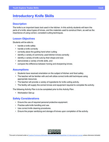
Door Basicstorsion springdrumspring supportrear track supportspringwarning tagend bearingtop fixturehorizontaltracktop section#3 section#2 sectionwarning labelbottom fixturebottom sectioncenter hingeend hingewarning labelvertical track(clip angle shown)Read and be sure that you completely understand all of the steps and warnings as outlined prior to beginning installation.Page 1
C.H.I. COMMERCIAL OVERHEAD DOORINSTALLATION INSTRUCTIONSThese instructions will show you how to install a C.H.I. Commercial door. They are for the mechanicallyexperienced person who has proper tools to perform the job. They are not meant to infringe upon orsupersede any State or County building codes or safety regulations.Included in this booklet are instructions for installing Standard Lift, High Lift, Vertical Lift and LowHeadroom doors mounted on Wood or Steel Jambs.Table of ContentsBefore You Begin.Opening PreparationInstalling Your New DoorSections and HardwareStrutsTrackSpringsLow Headroom DetailsSupplemental InstructionsAdjustable End BearingsIncline TrackSpring BumperBottom FixturesDouble Lock BarMaintenanceWarrantythis pagepage 3page 6page 8page 11page 17page 25page 30page 31page 32page 33page 34page 37page 38Before You Begin.Read and be sure that you completely understand all of the steps and warnings as outlined prior tobeginning installation!Safety First. Safety warnings are clearly marked with aWarning! symbol. Observe all guidelines andwarnings given in the instructions during installation and then review and post Maintenance and Warnings atback of booklet near the door for future reference.If you plan to use an existing door opener, check it for current safety features. This is the time to update youroperator to assure yourself of the safest door system possible.Warning! If you are removing an existing door, only an experienced person should release the springtension. The spring is the most dangerous part of your door. It is charged with force at all times andthis force must be properly and safely released before removing any part of your existing door. Seriousinjury or death may result if you attempt to loosen or remove any part of the spring system whether it isattached to the door or to the wall before releasing all of this spring force.Warning! Wear protective gloves and eye wear when working on your door.Warning! Strong winds or gusts can cause a partially installed door to fall.Copyright 2002 C.H.I. Overhead Doors12/02Read and be sure that you completely understand all of the steps and warnings as outlined prior to beginning installation.Page 2
Opening PreparationCheck opening size and door size.Door size and type are marked on the hardware carton label and spring tag. Check this information andcompare it with the actual opening size. Also check side room, headroom and back depth dimensions.Sample Hardware Carton Label505801Order #328516 x 7Strut Amount(5) 2" STRUTSModelDoor SizeInsulation TypeSpring TypeSTEELTOR. SPRING12 IN.Track TypeTrack Rad.Opening RequirementsTOR SPG AUXindicates auxiliary shaftsupports. Refer to instructionson pages 5 and 19.trackmountingopeningwidthopeningheightbracket mountsame as door widthsame as door heightangle mountsame as door widthsame as door heightreverse angledoor width minus 2"same as door heightSide room Requirements(for low headroom see page 25)1"opening widthopening widthdoor widthdoor widthdoor width 8" (2" track)door width 10" (3" track)door width 3-1/2" (2" track)door width 5"(3" track)1"Reverse Angle Track: Leg In(Steel Jambs Shown)Bracket Mounted TrackAngle Mounted Track: Leg Out(Wood Jambs Shown)Whenever possible allow more side room for ease of installation.Read and be sure that you completely understand all of the steps and warnings as outlined prior to beginning installation.Page 3
Headroom and Back depth Requirements for Standard Lift Doors(for low headroom see page 25)12" radius15" radiusdoor height 22"shaft center headroom shaft center headroomdrumspring heightMinimum values shown. Whenever possible allow more headroom for ease of installation.Add 2-1/2" to headroom if you are using a door opener.Headroom and Back depth Requirementsfor High Lift Doorsdrumshaft centerheadroomhl-54hl-120hl-164hl 6"hl 8"hl 10"hl 10"hl 13"hl 16"Headroom and Back depth Requirementsfor Vertical Lift Doorsadd 1" to shaftcenter and headroomfor 3" track.22"(door height 30") - high liftdoor height 20"headroomhighliftdoor height 6"door/openingheightdoor/openingheightRead and be sure that you completely understand all of the steps and warnings as outlined prior to beginning installation.Page 4
After you have checked that the door will fit, prepare the opening.It is very important that the opening is correctly prepared before installing tracks and springs. All mountingsurfaces must be structural components and not covered with drywall, paneling or any other buildingmaterial. The materials listed here are not supplied with the door.Torsion Spring Mounting Area iswhere the torsion springs will mount.It must be at least 10" wide x 10" high.Where shaft couplings are used,18" wide x 10" high.Header Plate provides a surface forthe door to seal against. It must belevel and flush with the jamb plates.opening width10"Seeheadroomcharton Page 4fortop ofjambsAuxiliary Shaft Support MountingArea is used to provide extra shaftsupport on large doors. see labelon page 3.Jamb Plates support the door tracks.Make sure that they are plumb andsquare with the header plate.door/openingheightRecommended Wood Framing Sizesspring mount2 x 10header plate2x 8aux. shaft support2x6jamb plate2x6Wood Framing should be Southern Pineor better structural species,grade2/better, free of cracks, splitsand knots.Reinforce torsion spring mounting areato a structural member with (4) 5/16" x4" wood lags.Floor: Start by checking that thefloor is level and smooth. The doorhas a weather seal on the bottomthat will adjust to minorirregularities.Recommended Steel Framing Sizesspring mount1/4 x 10aux. shaft support1/4 x 6Warning! Attachment of the jamb plates, header plate and torsion spring mounting area to buildingframework must provide adequate support to sustain the weight of the door, track and springassemblies as well as resistance to wind load forces and vibration caused by door operation.Read and be sure that you completely understand all of the steps and warnings as outlined prior to beginning installation.Page 5
Sections and HardwareAttach hardware to bottom section.The bottom section has weather seal attached to it. Set it on saw horses face down (the face is the outsideof the door). Apply hardware as shown below. Refer to tag on the hardware carton to see if this door willhave struts. If so, review pages 8 and 9.STEP 1STEP 3Sections are attached to each other with hinges.Fasten hinges marked #1 to top of bottom sectionat each stile using (2) 1/4" sheet metal screwsper hinge. Make sure that the two slots are attop of hinge. This allows for adjustment whenstacking sections. Attach each bottom fixturewith (4) red 1/4" sheet metal screws.The Door is held in the track with rollers. Insertrollers into bottom fixtures and end hinges.STEP 4STEP 2The door is raised and lowered byAttach cables to bottom fixtureseach side of the bottom section).bottom fixture details located onInstall inside step plate on an intermediate stileusing 1/4" sheet metal screws.special note for 3" tracklift cables.(one mounted onAdditionalpage 33.the end hinges on 3" track start with the #3hinges on the bottom section (there will not be #1or #2 end hinges). Additional bottom fixturedetails located on page 33.auxiliary end hinge(if double end stile)end hinge.#1 for first joint,#2 for second joint.etc.review pages 7 & 12.fixed pin bottom fixture(additional bottomfixture details locatedon page 33)auxiliary roller carrier(if double end stile)Warning! Fasteners used to attachbottom fixtures must be painted red.bottom fixtureFor low headroom doors see differences in bottom fixture design on page 26.Read and be sure that you completely understand all of the steps and warnings as outlined prior to beginning installation.Page 6
Selecting a top section.Use a 24" high section when available.If the door will be electricallyoperated, the operator must attach to astructural part of the section. Use thecenter stile for this purpose. Whenthere is an odd number of panels acenter stile is factory attached to thetop section.top sectionSandwich type doors with an oddnumber of panels will not have acenter stile; an operator mounting platemust be used. This mounting plate isnot supplied with the door. Contactyour C.H.I. door supplier.center stileintermediatestileIf a strut is required on this section,install it now (see pages 8 and 9).Prepare remaining sections for stacking.Apply #1 center hinges to intermediate stiles.If a strut is required, install it now (see pages8 and 9).intermediatesectionintermediatestileEnd Hinge progression.To allow door to 'breakaway' from jambs, the vertical tracks areangled out from the wall. Review page 12 for end hingeplacement. End hinges are designed to match the angle of thetrack. As hinge numbers increase so will the distance from hingetube to roller carrier.hingetuberollercarrierRead and be sure that you completely understand all of the steps and warnings as outlined prior to beginning installation.Page 7
Struts. (refer to page 9 for model 3214)Struts provide reinforcement of larger commercial doors. Not all doors will have struts. However, the topsection of a trolley operated door must include one. Struts are fastened at the same time as hinges.Warning! Installing a trolley operator without a top section reinforcing strut will void warranty.One strut per door: use on top section.Locate edge of strut approximately 1"down from section shoulder. Use 1/4"self drilling screws and strut clips toattach strut to intermediate stiles. Use1/4" self drilling screws to attach strut toend stiles. Top fixtures will be attachedafter horizontal tracks are in place.top sectionstrutTwo struts.Install one strut on top section. Installthe second strut on an intermediatesection approximately half way up door.Three struts.Install one strut on top section. Installthe second strut on an intermediatesection approximately half way up door.Install third strut on hinge line at top ofbottom section.More than three struts.Install one strut on the top and bottomsections. Space remaining struts asevenly as possible.Trussed struts.Very large doors may need extrasupport. This is done by addingtrussing to the strut. The truss bridgewill fit on top of the strut and attachesto the outermost intermediate stiles.Each set of trussing consists of two trussbridges, one turnbuckle and two lengthsof diatestilesend stilestrutThe turnbuckle is used to apply tensionto the strut. Tighten until the straps aretaut. Be careful not to over tighten theturnbuckle or the section will begin tobow and not set in the opening properly.turnbuckletruss bridge* Stiles not visible on model 3285.Stile location and strut attachmentis the same as shown.strapping1/4" self drilling screwRead and be sure that you completely understand all of the steps and warnings as outlined prior to beginning installation.Page 8
Struts. Model 3214 onlyStruts provide reinforcement of larger commercial doors. Not all doors will have struts. However, the topsection of a trolley operated door must include one. Struts are fastened at the same time as hinges.Warning! Installing a trolley operator without a top section reinforcing strut will void warranty.top sectionstrutOne strut per door: use on top section.Locate edge of strut approximately 1"down from section shoulder. This willinsure contact with the 3-3/4" horizontalbacker plate. Use 1/4" self drillingscrews and strut clips to attach strut.Top fixtures will be attached afterhorizontal tracks are in place.backer plateTwo struts.Install one strut on top section. Installthe second strut on an intermediatesection approximately half way up door.3-3/4"Three struts.Install one strut on top section. Installthe second strut on an intermediatesection approximately half way up door.Install third strut on hinge line at top ofbottom section.3-3/4"intermediatesectionbacker platestrutMore than three struts.Install one strut on the top and bottomsections. Space remaining struts asevenly as possible.Trussed struts.Very large doors may need extrasupport. This is done by addingtrussing to the strut. The truss bridgewill fit on top of the strut and attachesapproximately 4' from the section end.Each set of trussing consists of two trussbridges, one turnbuckle and two lengthsof strapping.1/4" self drilling screwused to anchor strutto each end of sectionend stilestrutThe turnbuckle is used to apply tensionto the strut. Tighten until the straps aretaut. Be careful not to over tighten theturnbuckle or the section will begin tobow and not set in the opening properly.turnbuckletruss bridgestrapping1/4" self drilling screwRead and be sure that you completely understand all of the steps and warnings as outlined prior to beginning installation.Page 9
If you have stop molding or clip-on seal, attach it to the jambs or track as shown.vinyl stop molding(nail on 6" centers)steel jamb1/8" - 1/4"clip-on sealPlace bottom section in the opening and mark reference lines for tracks.STEP 5Center and level bottom section inopening. If there is a gap on oneend at the floor then the trackwill not rest on the floor by thesame amount. Check this whenvertical tracks are in place.CENTER SECTIONIN OPENINGreference lineSTEP 6After section is leveled, measureup from bottom rail (do notmeasure from the vinyl weatherseal) same distance as door heightand mark a line on the jamb.reference line8"LEVEL SECTIONSTEP 7Measure down from the referenceline 8" (14" for low head room) andmark a level reference lineacross both jambs. This is wherethe lower vertical and upperhorizontal tracks will meet.DOORHEIGHTRead and be sure that you completely understand all of the steps and warnings as outlined prior to beginning installation.Page 10
Track InstallationPrepare the field bolted vertical tracks.STEP 1The top of the vertical track must pitch back from thejamb for the door to seal properly. This spacing is setby use of graduated track brackets. Attach but do notfully tighten brackets to track with 1/4" x 5/8" trackbolts and nuts.Always place heads of bolts to inside of the track. This willprevent rollers from striking bolts.nut6STEP 2two trackbracketsshown. Yourdoor may havemore dependingon door height.The flag angle mounts to the top of the track with (2)1/4" x 5/8" track bolts and nuts. This bracket joins thevertical and horizontal tracks as well as the angleattached to the horizontal track. Leave bolts loose atthis time. You will adjust the track after it isinstalled to the jambs.5.5Install vertical tracks.Bring cables up behind roller shafts. This will save you from having to thread them after the track isinstalled. Wood jambs shown. Use 1/4" jamb teks for steel jambs.STEP 1STEP 4Slip left hand vertical trackover rollers with a twistingmotion.Now loosen top of track andplumb it with the bottom.Check to make sure that thespacing at the bottom didnot change. Attach flagangle to the jamb with(3) 5/16" x 1-5/8" wood lags.STEP 2Position top of vertical trackeven with the reference linethat you marked on the jambs.Temporarily fasten track tojamb to keep it at correctheight. You will need to beable to plumb the track oncethe spacing at the bottom isset.STEP 3STEP 5reference line(step 7 page 10)Continue to fasten trackassembly to jamb withwood lags.STEP 6Install right hand tracksame way as left hand track.Space bottom of track leaving1/2" to 3/4" opening betweentrack and bottom section.Fasten bottom track bracketto jamb with 5/16" x 1-5/8"wood lag (always drill 3/16"pilot holes for wood lags).lagRead and be sure that you completely understand all of the steps and warnings as outlined prior to beginning installation.Page 11
Stack the sections in the opening.STEP 6STEP 1Continue to stack sections in openinguntil you come to the top section.Secure top section in opening with lockingpliers clamped to the track. Flip uphinges from section below and attachthem to the top section.Stack an intermediate section on top ofthe bottom (#1) section. This is shown asthe #2 section.STEP 2#1 center hingeBring up lift cables so they are betweenedge of door and track.locking pliersSTEP 3Slip roller stem into #2 end hinge usinghinge tube that will be farthest from door(see detail below). Insert roller intotrack. Attach end hinge (make sure thetwo slots are at the top of the hinge) totop of #2 section with 1/4" sheet metalscrews. Repeat at other end of section.topsection#3sectionSTEP 4With #2 section held in place by rollersand end hinges, flip up hinges from bottomsection and attach them to the #2 sectionwith 1/4" sheet metal screws.STEP 5#3 endhinge#2section#2 endhingeFor each section added you will usedifferent end hinges. The #3 section willuse #3 end hinges, the #4 section will use#4 hinges and so on.*Special Note for 3" TrackThe end hinges on 3" track start with #3end hinges on the bottom section (therewill not be #1 or #2 end hinges). The #2section will have #4 end hinges, the #3section will have #5 end hinges and so on.bottomsection#1 endhingeroller stemtrack(shown withtrack brackets)hinge tubeSTEP 3Read and be sure that you completely understand all of the steps and warnings as outlined prior to beginning installation.Page 12
Identify the type of upper track to be used.The first step is to look at what type of upper track attaches to your vertical tracks. Review the illustrationson page 4 to see what installation instructions you need to follow.Standard Lift: shown belowHigh Lift: page 14Vertical Lift: page 15Low Headroom: page 26Standard lift track installation.Standard lift doors will have a pair of horizontal curve tracks that will mount to the vertical track assembly.STEP 1STEP 2Use rope as a temporarysupport for the back of thehorizontal curve track. Alignrope with vertical track.Attach it to a structuraloverhead member.Fasten horizontal curvetrack to flag angle with (2)1/4" x 5/8" track bolts andnuts. Always place heads ofbolts to inside of the track.This will prevent rollersfrom striking bolts.STEP 3Fasten angle (attached tohorizontal curve track) toflag angle with 3/8" x 3/4"carriage bolt and nut.Always place heads of boltson same side as the doorsections. This will preventdoor from striking bolts.flag angleWarning! Rope, structural overheadmember, attachment and loop, must becapable of safely supporting four timesthe door weight.3/8" nutSTEP 3horizontalcurve trackSTEP 1to structuraloverhead member1/4" nutropeverticaltrackSTEP 2Read and be sure that you completely understand all of the steps and warnings as outlined prior to beginning installation.Page 13
High lift track installation.High lift doors with 24" or more of lift have an additional straight piece of track (see detail below). Highlift doors with less than 24" of lift have an extended vertical track and will install the same as standard lifttrack. Review page 13.Warning! Rope, structuraloverhead member, attachmentand loop, must be capable ofsafely supporting four timesthe door weight.STEP 1Fasten bottom of adder to flagbracket or mounting angle with (1) 1/4"x 5/8" track bolt and nut. Place bolthead on same side as door. This willprevent rollers from striking againstthe bolt. Attach adder to wall with5/16" x 1-5/8" wood lags or metalscrews (always drill 3/16" pilot holesfor wood lags).3/8" nutSTEP 4STEP 2ropetostructuraloverheadmember.STEP 3two 1/4" nutshorizontalcurve trackSTEP 2Use rope as a temporary support forback of horizontal curve track. Alignrope with vertical track. Attach itto a structural overhead member.STEP 11/4" nut7" less thanamountof high liftSTEP 3Fasten horizontal curve track with(2) 1/4" x 5/8" track bolts and nuts.Always place heads of bolts to insideof track. This will prevent rollersfrom striking bolts.vertical track(shown withmounting angle)STEP 4Fasten angle (attached to horizontalcurve track) to wall angle with 3/8"x 3/4" carriage bolt and nut.Always place heads of bolts on sameside as door sections. This willprevent door from striking bolts.Read and be sure that you completely understand all of the steps and warnings as outlined prior to beginning installation.Page 14
Vertical lift track installation.Vertical lift doors do not have a horizontal track.The upper track is straight, similar to the verticaltrack, and is mounted to a wall angle. A horizontalangle connects the track to the top of the wall angle.STEP 1Fasten upper track to flag bracketor mounting angle with (2) 1/4" x 5/8"track bolts and nuts. Always placeheads of bolts on same side as door.This will help prevent rollers fromstriking against the bolts.uppertrack1/4" nutsSTEP 2Plumb upper tracks with verticaltracks and attach to wall with 5/16"x 1-5/8" wood lags or metal screws(always drill 3/16" pilot holes forwood lags).vertical track(shown withmounting angle)Read and be sure that you completely understand all of the steps and warnings as outlined prior to beginning installation.Page 15
Attach top fixtures and rollers.(for low headroom doors see page 27)Finish applying door hardware by attaching top fixtures and rollers to the top section.Review pages 8 and 9 if your door includes a top strut.Loosen adjustment bolt in top fixture.Slip roller stem into roller carrier.Insert a roller into the track. Positiontop fixture about 1" from section top.Holes in fixture will line up with holes inend stiles. Attach top fixture with1/4" sheet metal screws. Adjust topfixture roller carrier so door sealsfirmly against stop molding.Warning! Rope, structuraloverhead member, attachmentand loop, must be capable ofsafely supporting four timesthe door weight.topfixtureto structuraloverhead member.rollerrope1/4"sheet metalscrewauxiliary top fixture(if double end stile)vertical track(shown with mounting angle)Attach the pull rope.Warning! If this door is to be electrically operated, do not install the pull rope. The use of a pull ropeon a non-manually operated door can cause serious injury.For manually operated doors attach an eye screw to the jamb at about 50" from the floor. Tie one end of pullrope to roller stem on bottom fixture between the two tabs that hold the roller. Tie other end of the rope toeye screw.Inspect the work which you have done for missing parts or loose fasteners.Before moving on, check that all of the fasteners used in the track system are in place and tight. Also checkthat applied hardware is in place and securely fastened.Read and be sure that you completely understand all of the steps and warnings as outlined prior to beginning installation.Page 16
Torsion Spring Assembly DetailsSpring systems will vary according to the door model, size and options. While you are assembling the springline, take time to study the parts and identify them.Torsion Springs: Torsion springs supply the force to raise the weight of the door. Torsion springs are undertension and rotate about a shaft as they operate. Initial tension is loaded into springs using spring winding bars(not supplied). Torsion springs come in different coil diameters, wire sizes and lengths. Each torsion springhas a retainer and a winding plug mounted on the ends. The retainer holds one end of the spring stationary andis mounted to a spring bracket. The winding plug at the other end of the spring is fastened to the shaft with setscrews and transfers spring force to the spring shaft. See illustration on page 19.Spring Shaft: The spring shaft transfers force from the springs to the cable drums. The shaft may come in oneor two pieces. The one piece will span the entire door width while the two piece will be coupled together at thecenter.Cable Drums: Cable drums transfer spring force to the door by use of lift cables. Cable drums will differ indesign according to the upper track system and door weight.Spring Bracket: Holds spring system to wall.End Bearing Plates: End bearing plates support the spring shaft and allow it to rotate freely while door ismoving.Check all spring assembly instructions and parts.Warning! If there appears to be any parts missing stop here and contact your C.H.I. door supplierimmediately. Do not substitute parts.Warning! Do not remove any factory applied spring tag or warning label! If any tags or labels aremissing or unreadable, contact your C.H.I. door supplier immediately.Secure door in fully closed position.Warning! Securing door in the fully closed position will prevent any unexpected door movementwhile you are working on the spring system. Failure to do so could result in serious injury or death.#3 sectionSecure door using the lock. If your door is notequipped with a lock, attach locking pliers toeach vertical track just above rollers at thesecond hinge line (from bottom of door).lockingpliersend hingevertical track(shown with mounting angle)#2 sectionRead and be sure that you completely understand all of the steps and warnings as outlined prior to beginning installation.Page 17
Install end bearing plates.(for( low headroom doors note different end bearingplates as shown on page 27)end bearing plate3/8" x 3/4"carriage bolts(supplemental end bearing instructions are on page 30)wall angleAttach end bearing plates tohorizontal angle using (2) 3/8" x 3/4"carriage bolts and nuts. Alwaysplace heads of bolts on same side asdoor sections. This will preventrollers from striking the bolts.end bearingplateAttach spring supports to the spring mounting area.STEP 1springmountingareaSnap a chalk reference line acrossthe top of the end bearing platesonto the spring mounting area.STEP 2rUse the illustrations on pages 5, 19and 20 to help you determine wherethe spring brackets will be placed.Mark these locations on thereference line (allow 10" betweenbrackets when shaft couplings areused). Measure from the top of oneend bearing plate to the center ofthe bearing ("a"). Mark this samedistance "a" down from the referenceline where the spring brackets willbe located. This will indicate thecenter of the spring shaft.horizontal anglerefeenceelin"A""A"STEP 3Fasten each spring bracket (see pages19 and 20) to the spring mounting areausing (2) red 5/16" x 1-5/8" wood lagsor metal screws. If auxiliary shaftsupports were provided, locate them 10"in from each jamb. Position andattach in the same manner as thespring brackets.Identify torsion springs. (for low headroom doors note differences in spring placement as shown on page 28)Springs are single or in pairs based on door design and track system. It is important to determine the 'wind'of a spring before installation. A 'right hand wound spring' will have a red winding plug. A 'left hand woundspring' will have a black winding plug. Cable drums are also color coded. The red drum will be on the leftside of the spring assembly and the black drum on the right side. Match color of winding plug on springwith drum.Spring wire is woundcounterclockwiseSpring wire is woundclockwiseright hand wound(red winding plug)left hand wound(black winding plug)Read and be sure that you completely understand all of the steps and warnings as outlined prior to beginning installation.Page 18
Pre-assemble spring line and mount it to spring support.(for low headroom doors note differences in spring system layout as shown on pages 28 and 29)For illustrative purposes, two springs are shown. Your door may have a single spring. If so, follow thedetails for that color of spring.Review spring assembly diagram andassemble all components on springshaft. If the springline has acoupling see page 20.cable drum (red)set screwsfacing springwinding plug(red)Auxiliary Shaft Support Detail.(See hardware carton to determine if your doorhas Auxiliary Shaft Supports. A sample hardwarecarton tag is located on page 3.)approximately 10" from jambflange bearing3/8" x 3/4"carriage boltwith hex nutspring supportRead and be sure that you completely understand all of the steps and warnings as outlined prior to beginning installation.Page 19
Pre-assemble spring line with shaft coupling.(for low headroom doors note differences in spring system layout as shown on pages 28 and 29)Review spring assembly diagram andassemble all components on springshaft. you may want to install oneshaft at a time and then connectthe coupling halves together.cable drum (red)set screwsfacing springwinding plug(red)Auxiliary Shaft Support Detail.(See hardware carton to determine if your doorhas Auxiliary Shaft Supports. A sample hardwarecarton tag is located on page 3.)approximately 10" from jambflange bearing3/8" x 3/4"carriage boltwith hex nutspring supportRead and be sure that you completely understand all of the steps and warnings as outlined prior to beginning installation.Page 20
Secure spring shaft and fasten cables to drums.(for low headroom doors note differences in spring system layout as shown on pages 28 and 29)STEP 1STEP 2STEP 3Position left hand cabledrum (red) against endbearing plate. Insert cableinto slot on drum edge.Firmly seat the cable lug inthe drum. Rotate drum towind up cable until it istaught. Tighten set screwssnug. Do not exceed 30 footpounds of torque.Restrain spring shaft withlocking pliers to keep shaftfrom turning. Use wall tohold locking pliers in place.Movement of shaft maycause slack in cable.Position right hand cabledrum (black) ag
C.H.I. COMMERCIAL OVERHEAD DOOR INSTALLATION INSTRUCTIONS Included in this booklet are instructions for installing Standard Lift, High Lift, Vertical Lift and Low Headroom doors mounted on Wood or Steel Jambs. Read and be sure that you completely understand all of the steps and warnings as outlined prior to beginning installation. Page 2