Transcription
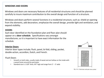
RESIDENTIAL SECTIONAL INSULATED STEEL DOORSI N S TA L L AT I O NI NSTRUCTI O NSCONSUMER SERVICES 1-800-621-3667INSTRUCTIONS COMPATIBLE WITH THE FOLLOWING MODELSTraditional Steel Panel Doors MRP68U, MDP68U, MRP38U, MDP38U, MRP68, MDP68, MRP38, MDP38 // Designer Steel Panel Doors MR2LU, MR2SU, MR1LU,MR1SU, MR2LP, MR2SP, MR1LP, MR1SP, RR1EU, RR1NU, RR2EU, RR2NU // Modern Steel Panel Doors MCC68U, MFC68U, MFL68U, MFR68U, MRC68U, MCC38U,MFC38U, MFL38U, MCC68, MFC68, MFL68, MRC68, MCC38, MFC38, MFL38, MFR68 // Premium Handcrafted Doors MWL2, MXU, MX, MFSTEP 1 - BEFORE YOU BEGINTABLE OF CONTENTSVerify you have all parts and materials required for installation.STEP 2Read Safety Information . . . . . . . . . . . . . . . . . . . . . . . 2 Door Components (See Page 5).STEP 3Check Headroom, Backroom, Sideroom . . . . . . . . . . . . 3If missing parts or damaged sections, call ConsumerServices Hotline 1-800-621-3667.STEP 4Review Complete Door Assembly and Verify Hardware . 4–6STEP 5Remove the Existing Door . . . . . . . . . . . . . . . . . . . . . . . 7 Read instructions completely and/or watch installation video.STEP 6Prepare the Opening . . . . . . . . . . . . . . . . . . . . . . . . . . . 8 HEADROOM: Verify appropriate amount of headroom to install door(STEP 3).STEP 7Prepare the First (Bottom) Section . . . . . . . . . . . . . 9–10STEP 8Install Lift Handles . . . . . . . . . . . . . . . . . . . . . . . . 11–13 LOW HEADROOM: Special instructions and additional hardware may berequired (STEP 3, Table 3-B).STEP 9Install Door Sections . . . . . . . . . . . . . . . . . . . . . . . 14–16 INSTALLATION TIME: Allow enough time to complete installation.Garage will be open and unsecured during installation and will not beable to be used until tracks are installed. STEP 10 Reinforce the Top Section for Garage Door Opener. . . . . . . . . . . . . . . . . . . . . . . . . . . . . . . . . . . . . . . 17–18STEP 11 Assemble and Install the Track . . . . . . . . . . . . . . . 19–21STEP 12 Install Lock (If Included) . . . . . . . . . . . . . . . . . . . . . . . 22 Removing existing door will take approximately 1–3 hours.STEP 13 Install Pull Rope (Manually Opened Doors Only) . . . . . . 22 Typical installation time is 9–12 hours.STEP 14 Install Springs . . . . . . . . . . . . . . . . . . . . . . . . . . . . . . . 22TRACK AND HARDWARE: Express warranties apply only to doorsinstalled using original, factory-supplied sections, parts and hardwareand in strict adherence with these instructions.STEP 15 Attach Automatic Garage Door Opener . . . . . . . . . . . . 23WARNINGNever reuse old track or hardware when installing a new door as it maycause installation problems or door to fall which could result in seriouspersonal injury or property damage. AUTOMATIC DOOR OPENER: Installation of a reinforced mounting pointis required to avoid damage (STEP 10). Sold separately. DRILLING: Take care not to drill through outside steel skin unlessotherwise instructed. HIGH WIND AREAS: Doors installed in high windload regions (Floridaand other high wind-prone areas) may require additional reinforcement.Refer to Supplemental Instructions for details if applicable. PAINTING DOOR: If planning to paint door, follow directions in Care& Maintenance section. Ideal Door recommends painting door andallowing it to dry completely before beginning install.GENERAL MAINTENANCE & CARE . . . . . . . . . . . . . . . . . . . . . 25–31WARRANTY . . . . . . . . . . . . . . . . . . . . . . . . . . . . . . . . . . . . . . . . . 32
STEP 2 – READ THIS SAFETY INFORMATION - IMPORTANT!!WARNINGTO PROTECT YOURSELF FROM INJURY, YOU MUST CAREFULLY READ THE FOLLOWING SAFETY INFORMATION AND WARNINGS BEFORE YOU INSTALL OR USE YOUR NEW GARAGE DOOR!BEFORE INSTALLING YOUR DOOR You can install your new garage door yourself if: a) you have help (it may weigh up to 150 lbs.) b) you have the right tools and reasonable mechanicalaptitude or experiencec) you follow these instructions very carefullyGarage doors use springs to balance them. There are two typesof springs – extension or torsion. Each of these is available ineither a standard or EZ-SET assembly option. Please look atthe drawings on Page 4 to see which springs your old door has.If your door has a different type of spring, consult the originalmanufacturer’s instructions for removal.If your old door uses torsion springs, do not attempt to remove thedoor or the springs yourself. Have a qualified door repair serviceremove them. Attempting to remove a torsion spring assemblywithout proper training or tools may result in an uncontrolledrelease of spring force which can cause serious or fatal injury(Page 4).In removing a garage door that has extension springs, follow theinstructions carefully (Page 7), including the use of C-clamps orlocking pliers on both sides of the door in order to keep the doorfrom moving once the springs are removed.Springs, cables and bottom fixtures are under strong spring tension. Do not attempt to loosen any fasteners on these components. You could suddenly release spring forces and risksevere injury.Doors equipped with automatic garage door openers can causeserious injury or death if not properly adjusted and operated.To ensure safety of these doors:a) test the sensitivity of the garage door opener’s safetyreverse mechanism monthlyb) if your door has a pull-down rope, you must remove it c) make sure the door remains unlockedd) ensure door is properly reinforcede) do not allow children to play with the controls DO NOT attempt to install the door during windyweather conditions. The door sections may be blowndown causing serious injury or property damage.WHILE INSTALLING YOUR DOOR !2Bolts must be installed at the rear end of horizontal tracks. Theseact to stop the rollers and keep the door from rolling off the backof the track.Track installations must use sway braces on the rear track hangers to prevent sideways movement. If the tracks are notfirmly stabilized they might spread, allowing the door to fall andcause severe injury and damage.Do not attach any brackets directly to drywall or sheet rock. Alltrack brackets, flag brackets and spring brackets should only beattached directly to 2" 6" wood jambs. Otherwise, bracketscould pull out of the drywall with dangerous force.AFTER INSTALLING YOUR DOORManufacturer disclaims all liability for any installation that is not incompliance with these installation instructions or applicable stateor county building codes.In the interest of safety this symbol means WARNING orCAUTION. Personal injury and/or property damage mayoccur unless instructions are followed carefully.Use only the track specified and supplied with the door.The brackets at the bottom corners of your garage door are undergreat tension. Do not attempt to loosen any bracket fastenersexcept when and as directed in detail in the following instructions.Otherwise, the bracket could spring out with dangerous force.Do not permit children to play beneath or with any garage door orelectronic operating controls.Keep hands and fingers clear of section joints, track and otherdoor parts when the door is opening and closing to avoid injury.In particular, do not place fingers in section joints in order to closethe door, as finger pinch, crush or amputation will result. The lifthandles are located for safe operation as well as easy use.If the garage door and/or any of the supporting track are damaged, operating the door could be hazardous. ContactConsumer Service Hotline.If repairs are ever required to your door, safety and trouble-freeoperation can be best assured by using original replacement parts.Once you have completed the installation of your new garagedoor, please be sure that your garage complies with all applicableventilation requirements before you enclose any vehicles in thegarage. Good ventilation avoids fire and health hazards caused byfumes accumulating within a well-sealed garage.Only approved residential garage door openers are permitted tobe used in residential applications. A residential application is abuilding for four families or less, or a garage that is serving theprimary residence.Install operator control panel away from garage door track andthe door itself. Keep body parts away from track at all times whenoperating an opener or opening/closing a garage door.
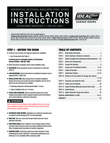
STEP 3 - CHECK HEADROOM, BACKROOM, SIDEROOMHeadroom Requirement: Headroom is space needed above top of door for door, overhead tracksand springs. Measure to check that there are no obstructions within thatspace (Fig. 3-A). Refer to Table 3-A for standard headroom requirements. Track radius can be determined by measuring dimension “R”(Fig. 3-B).Rough Opening Door SizeBackroom DoorHeight Plus 18"HeadroomRequired If “R” equals 11" to 12", it is a 12" radius track. If “R” equals 14" to 15", it is a 15" radius track. NOTE: If there is restricted headroom, several low headroom remediesare available (Table 3-B). Installation of these options differ frominstallation of a standard headroom door.Supplemental instructions are included with hardware of each lowheadroom option.4-1/2" Minimum SideroomFig. 3-AFig. 3-ARough Opening: DoorHeightDetermine which type of spring you have (STEP 4).Rough opening (minus stop mold) same size as door (Fig. 3-A)Backroom Requirement: Measured from back of door into garage, and should be at least18" more than height of garage door (Fig. 3-A).RSideroom Requirement: Minimum 3-3/4" is needed on each side of door on interior wall surfaceto allow for attachment of vertical track assembly. Minimum 4-1/2" is needed on each side of door above opening fortorsion spring attachment.NOTE: If you are installing an automatic opener, about 3" of additionalheadroom at the center plus additional backroom is needed. Checkdoor opener instructions.Fig. 3-BTable 3-A: Standard Headroom Requirement ChartSpring TypeExtension SpringTrackRadiusHeadroomRequired12"10"Extension Spring15"12"EZ-SET Torsion Spring or Torsion Spring12"12"EZ-SET Torsion Spring or Torsion Spring15"14"Table 3-B: Low Headroom Options*Spring TypeLow Headroom OptionReduces Required Headroom to:How can I get this option?ExtensionLow Headroom Track4-1/2"Order Low Headroom TrackExtensionLow Headroom Conversion Kit(Modifies Standard Track)4-1/2"Available at most retail storesExtensionQuick Turn Bracket8" on 12"Radius TrackOrder Quick Turn Bracket SetEZ-SET TorsionLow Headroom Track(Front Mount Spring)9-1/2"Order Low Headroom TrackEZ-SET TorsionLow Headroom Conversion Kit(Modifies Standard Track)9-1/2"Available at most retail storesTorsionLow Headroom Track(Front Mount Spring)9-1/2"Available from and should be installed byprofessional installer onlyTorsionLow Headroom Track(Rear Mount Spring)4-1/2"Available from and should be installed byprofessional installer only3
STEP 4 - REVIEW COMPLETE DOOR ASSEMBLY AND VERIFY ALL HARDWARE IS TypicalGarageGarage DoorDoor stemShownonDoorEXTENSION SPRING SYSTEM cluded)(NotContainmentCable ionary SheaveSheaveStationary SheaveSheaveDoor JambDoor JambFlag BracketFlag BracketSection #4Top BracketSection #4Top BracketTop BracketTop VerticalBracketTrackVertical TrackOperatorLabel#3 HingeSection #3#3 Hinge#1 HingeGeneral Safety LabelSection #3General Safety Label#2 HingeSection #2#2 HingeSection#1#2Hinge#3 Hinge#1 HingeLong Track Bracket#1 Hinge#2 HingeLong Track Bracket#1 HingeSerial Number Label#2 Hinge#1 Hinge#1 Hinge#1 HingeShort Track Bracket#1 HingeBottom BracketSerial Number LabelVertical TrackOperatorLabelVertical Track#3 HingeInside Step Plate#1 HingeBottom BracketShort Track BracketBottom BracketBottom BracketStep PlateStandard Extension InsideSpringSystemSPRING SYSTEMSStandard Torsion Spring SystemSheaveSTANDARDExtensionEXTENSION SPRINGStandardSpringSYSTEMSystemEnd Bearing PlatesTorsion ON SPRINGCenter Bearing PlateSheaveEnd Bearing PlatesTorsionTubeRed WindingConeStationary SheaveLeft (Red)Cable DrumStationary SpringSheaveEZ-SET ExtensionSystemSheaveCenter Bearing PlateStationaryConeBlack WindingConeRed WindingConeRight (Black)StationaryCable DrumConeEZ-SET TorsionSpring SystemBlack WindingLeft (Red)Cable DrumConeEZ-SET eaveEZ-SET Winding UnitRight (Black)Cable DrumEZ-SETWinding Unit EZ-SET TORSIONSYSTEMEZ-SETTorsionSPRINGSpringSystemLeft Cable DrumEZ-SETEZ-SET Bracket Winding UnitLeft Cable DrumEZ-SET Winding UnitUnit EZ-SET BracketNOTE: The above illustrations represent a composite of many features found on a variety of garage doors. While not representative of any one door, itprovides a handy reference for the location of specific components. Doors with torsion springs may require EITHER one or two springs depending onthe door weight. Consult your spring manual.4
HARDWARE COMPONENTS INCLUDEDNOTE: All doors will receive (1) spring kit and (1) or more springs. Separate spring installation supplemental instructions should be included with doorhardware. This supplement contains a list of all spring related hardware along with instructions on proper spring installation.Qty SingleDoorsX' 7'Qty DoubleDoorsX' 7'Track Bracket (longer)22Track Bracket (shorter)2#1 Hinge#2 HingeImageDescription#3 HingeQty SingleDoorsX' 7'Qty DoubleDoorsX' 7'Cable Assembly222Struts*01 or 3511Lift Handle2222Pull Rope11#14 5/8" Hex HeadSheet Metal Screw56901/4" 3/4" Hex HeadSelf-Tapping Screw0101/4" 5/8" Track Bolt16223/8"-18 3/4"Lg. Carriage Bolt223/8" Washer222Image2Description#4 Hinge (5-section doors only)22Top Bracket22Bottom Bracket (1) LH (1) RH22Flag Bracket (1) LH (1) RH221/4" Flange Nut1622Horizontal Angle223/8" Hex Nut22Curved Horizontal Track22RollersVertical Track225/16" 1-5/8" Lag BoltInside Step Plate2210 (4-section Doors)12 (5-section Doors)10 (4-section Doors)12 (5-section Doors)ADDITIONAL HARDWARE COMPONENTS INCLUDEDONLY WITH COMPOSITE OVERLAY FAUX WOOD DOORS & STEEL CARRIAGE HOUSE DOORSImageDescriptionVertical Spade HandleHandle SpacersBackup PlateDoor SizeQty.ImageDescriptionDoor SizeQty.Single Car Doors8'–9'W24Double Car Doors16'W4Single Car Doors8'–9'W6Single Car Doors8'–9'W1Double Car Doors16'W10Double Car Doors16'W2Single Car Doors8'–9'W1Single Car Doors8'–9'W6Double Car Doors16'W2Double Car Doors16'W10Single Car Doors8'–9'W2Double Car Doors16'WRoll Grip HandleHorizontal Spade HandleBlack Head Carriage BoltSee next page for Additional Materials Needed (Not Included).5
ADDITIONAL MATERIALS NEEDED (NOT INCLUDED)* More struts may be required in high windload areas. (While not representative of any one model, the quantities below can be used as a guide.In some instances, extra screws/bolts are provided in the event of strip-out or loss of parts.)MATERIALS NEEDED (NOT INCLUDED)GeneralRear Track Hanger Specific (1) Can of Ideal Door Pro-Lube Wood shims (1) Rear Track Hanger Kit or material to make track hanger Wood block (24) 10d 3" common nails Rope 1-1/4" 1-1/4" minimum 13 ga. (3/32") minimum thicknesspunched angle Stop molding (10) 3/8" 1" bolts and nuts (6) 5/16" 1-1/2" lag screwsTOOLS NEEDED (NOT INCLUDED) Work gloves Level Stepladder Hacksaw Safety goggles Socket wrench set 7/16" and 9/16"box wrenches Sawhorses (with non-abrasivecarpet or other soft material ontop surface) or other supportsfor placing section on whileassembling Wood saw C-clamps or locking pliers Hammer Flathead screwdriver Measuring tape6 Drill, 1/4", 3/16" and3/8" drill bits, 7/16" and 9/16" drive bits Angle square Additional tools may berequired for spring installation
STEP 5 - REMOVE THE EXISTING DOOR Step 5-1: Remove Existing Door SpringsNOTE: Garage doors use springs to balance door weight. Springs areone of two types – extension or torsion. Each of these is available ineither a standard or EZ-SET assembly option. Use illustrations in STEP 4 to determine which springs existing doorhas. If existing door's spring type is not found, please consult springmanufacturer.WARNINGC-clampSerious injury could result from an uncontrolled release of spring forcesif spring tension has not been released before other work begins.Fig. 5-AWARNINGTo avoid pinch and other crushing injuries, keep hands and fingers clearof section joints, track and other door parts while door is opening andclosing.NOTE: Some large doors can weigh as much as 500 lbs. and single cardoors as much as 200 lbs. when spring tension is removed.Standard Torsion Springs:WARNINGIf present door uses standard torsion springs, DO NOT attempt to removedoor or springs yourself. They should be removed by a qualified doorservice professional. Attempting to remove a torsion spring assemblywithout proper training and tools may result in an uncontrolled release ofspring forces which can cause serious injury.Standard Extension Springs:WARNINGExtension adjustments or removal should only be made with door in upposition. To avoid damage or serious injury from door falling, use two ormore helpers to assist in lowering door.Fig. 5-BFig. 5-BEZ-SET Extension Springs or EZ-SET Torsion Springs:WARNINGTo avoid damage or serious injury, use two or more helpers to assist inlowering door. EZ-SET torsion springs adjustments or removal shouldonly be made with door in down position. With door in down position, position drill with 7/16" socket bit overwinding unit. Using reverse (counter-clockwise) direction on drill, remove all tensionfrom spring. Repeat for each side. Raise door to full open position. Place C-clamps or locking pliers tightly on both sides of track under doorso door is held securely in place (Fig. 5-A).After spring tension has been removed, detach lift cables atboth ends. Disassemble and remove springs and cable completely from door. With door fully open, most spring tension has been removed. Keeping C-clamps in place to keep door from falling, detach cable at bothends. Disassemble and remove springs and cable completely from door.NOTE: Wood blocks should be placed underneath door when closing toprevent fingers from being trapped. Remove C-clamps from track and carefully close door. Weight of door will not be apparent when you first begin to close door.Door will feel progressively heavier as it is lowered until its full weight isrealized about one foot from floor.Step 5-2: Remove Door Sections and Track After removal of door springs, door can now be disassembled. Starting with top section, remove hardware and unstack sections one ata time (Fig. 5-B). After all sections have been removed from opening, detach all remainingtrack and hardware from jambs. Hangers that attach rear ends of overhead track to ceiling (rear trackhangers) in many cases can be reused on new door. B e sure they aremade of 13 ga. (3/32") or heavier steel and are not loose or unstable.WARNINGTo avoid installation and operation problems from using worn, damagedor incompatible track, use only track specified and supplied with door.DO NOT attempt to reuse old track.7
STEP 6 - PREPARE THE OPENINGRequired HeadroomNOTE: Rough opening (framed opening without stop molding) doorsizeStep 6-1: Framing If old door was removed, inspect jambs for rotted or damaged wood andreplace immediately. Inside of door opening should be framed with 2" 6" lumber. Vertical jamb should extend past opening (Fig. 6-A) to match headroomrequired (Table 3-B). Jambs should be plumb and header should be level. Be sure bolts fastening jambs to wall are flush. Step 6-2: Stop Molding Door stop molding should be temporarily but securely nailed to edges ofjambs and flush with inside framing (Fig. 6-B) .NOTE: Stop molding with built-in weatherseal is offered.2x6Header JambOpeningHeight4-1/2" MinimumSideroomfor Torsion Spring2x6Side JambOpeningWidthInside of GarageLooking Out8"MinimumCenterPost(WithTwoDoorsSideBy Side)Fig. 6-AStopMoldingOutsideInsideFig. 6-B8
STEP 7 - PREPARE FIRST (BOTTOM) SECTIONStep 7-1: Locate Bottom Section Find section with aluminum weatherstrip retainer fastened to one edge.Retainer is on bottom edge of bottom section (Fig. 7-A). Cover sawhorses with carpet or cloth as not to scratch section. Place section on sawhorses face down.Step 7-2: Attach Bottom Brackets By hand, bend to break apart bottom brackets as shown (Fig. 7-B).Remove connecting tabs. Slide bottom bracket up to fully engage safety tabs into slots on stile(Fig. 7-C). Using (2) #14 5/8" sheet metal screws, attach bottom brackets tobottom corners of door section.Fig. 7-AAluminum Weatherstrip RetainerFig. 7-BFig. 7-BWARNINGFailure to properly engage safety tabs on bottom bracket into slots onedge of door may cause sections to fall or spring to break free whenspring tension is applied, which can result in severe injury.Step 7-3: Attach Standard Extension Springs Lift CablesNOTE: For Standard Extension Springs — lift cables are the longer andsmaller diameter of the two sets of cables. DO NOT use shorter safetycontainment cables as lift cable, this can cause improper door function.For EZ-Set Extension Springs — DO NOT attach lift cables now, thiswill be done when springs are installed. Hook looped ends of lift cable over buttons on bottom brackets(Fig. 7-D).Step 7-4: Attach Hinges #14 x 5/8" Sheet Metal ScrewsBottom SectionSlots!EngageSafetyTabsFig. 7-CBottomBracketWeatherstripSafety TabsFig. 7-DHinges are stamped with numbers 1, 2 and 3 on the side of the hinge thatattaches to the section. (Number 4 is stamped on 5-section door only.)#1 HingeAttach a #1 hinge to each pair of prepunched holes along top edge ofsection using (2) #14 5/8" sheet metal screws per hinge (Fig. 7-E).NOTE: Determine if a strut is required on the bottom section of yourdoor (Table 7-A). Determine whether door thickness is 1-3/8" or2" and the width of the end stile (Fig. 7-E). To attach strut, overlaphinges using 1/4" 3/4" self-tapping screws as shown (Fig. 7-F).When predrilled holes do not line up with hinge, drill (2) 3/16" pilotholes through strut, hinge and door at each location (or use impactwrench with 7/16" socket and self-tapping screws (Fig. 7-F).#14 x 5/8"Sheet Metal ScrewsBottomAstragalEnd StileWidthDoorThicknessFig. 7-E1/4" x 3/4" SelfTappingScrewsStrutEnd HingeFig. 7-FEnd Stile9
STRUT REQUIREMENTSTABLE 7-A: CLASSIC STEEL DOORS & CONTEMPORARY STEEL DOORSThe table below shows the strut requirements for insulated doors.The table below shows the strut requirements for Steel Carriage House doors.Door ThicknessDoor WidthStruts Required1-3/8"Up to 14'10"None1-3/8"15'–16'(1) 2-1/4" Strutper door (top)1-3/8"16'2"–18'(1) 2-1/4" Strutper section2"Up to 15'None2"15'2"–20'(1) 2-1/4" Strutper door (top)SectionDoorThicknessDoorWidthEnd StileWidthBottom3rd*Top1-3/8"Up to 14'10"All–––1-3/8"15'–16'2-1/2"–– 1-3/8"16'2"–18'2-1/2"2"Up to 15'All–––2"15'2"–20'All–– One strut per section*Section with general safety label.NOTE: Doors installed in high windload regions (Florida and other highwind-prone areas) may require additional reinforcement. Refer toSupplemental Windload Instructions.TABLE 7-B: COMPOSITE OVERLAY FAUX WOOD DOORS &COMPOSITE OVERLAY DOORSThe table below shows the strut requirements for composite doors.STRUT REQUIREMENTDoorWidthUp to 2" Thick2" ThickCompositeWood FullVisionUp to 9'0"NoneNoneNone9'2" to 12'2"(1) 2-1/4" Strutper door (top)(1) 2-1/4" Strutper door (top)(1) 2-1/4" Strutper door (top)12'4" to 16'2"(1) 2-1/4" Strutper section(1) 2-1/4" Strutper section(1) 2-1/4" Strutper section16'4" to 18'2"(1) 3" Strutper section(1) 2-1/4" Strutper section(1) 2-1/4" Strutper section18'4" to 20'0"N/A(1) 3" Strutper section(1) 3" Strutper sectionNOTE: Window Lite section on double car doors may be packaged withtwo struts attached. Remove strut from bottom of window section andplace on top of section #3.TABLE 7-C: STEEL CARRIAGE HOUSE DOORS10
STEP 8 - INSTALL LIFT HANDLESSTEP 8A: FOR INSULATED GARAGE DOORSNOTE: For Composite Doors proceed to STEP 8B. For Steel CarriageHouse Doors, proceed to STEP 8C.2ND SECTIONCUT HERE FOR1-3/8" DOORSStep 8A-1: Lift Handle Preparation For 2" thick doors, no modifications are necessary. For 1-3/8" thick doors, cut stems on lift handle along ridge line using ahacksaw (Fig. 8A-A).LIFTHANDLESTEMSStep 8A-2: Bottom (First) Section Fig.8A-AFIG 8-AFrom front side door section, drill (2) 1/2" holes through section accordingto Bottom Section Hole Pattern (Fig. 8A-B). Use T-square to ensurevertical alignment.(BOTTOM OF LIFT HANDLE)LIFTHANDLENOTE: If door has an outside keyed lock, hole pattern should be drilledon bottom section directly below lock. If door does not have an outsidekeyed lock, hole pattern should be drilled directly below hinge closestto horizontal center of door. INSIDESTEPPLATELIFTHANDLEInstall lift handle and inside step plate using (2) #14 5/8" sheet metalscrews (Fig. 8A-B).BOTTOM SECTIONIMPORTANT: Use wrench or socket to drive screws. Do not overtighten. DO NOT use an electric drill or driver.Step 8A-3: Second (Lock) SectionINSIDE STEPPLATETo be installed at completion of STEP 9A-4. Not required for door withoutside keyed lock. From front side door section, drill (2) 1/2" holes through section accordingto Second Section Hole Pattern (Fig. 8A-C). Use T-square to ensure theyare vertically in line.NOTE: Hole pattern should be drilled directly above hinge closest tohorizontal center of door. Fig.Fig.8A-B8-BInstall lift handle and inside step plate using (2) #14 5/8"sheet metal screws (Fig. 8A-B).2" DOOR SHOWNIMPORTANT: DO NOT use these prestamped hinge holes for lift handleplacement. Measure per the drilling pattern below. DO NOT use thistemplate for carriageDOstyleoverlaydoors.NOTorUSETHE PRESTAMPEDHINGE HOLESPainting Lift HandlesFOR LIFT HANDLE PLACEMENT – MEASUREPER THE DRILLING PATTERN BELOW. Plastic lift handles can be painted using good quality spray-on orbrushed-on enamel paint.Measure to Hinge Holeson Opposite Side#14 x 5/8"SHEET METALSCREWLift Handle Hole Drilling PatternOutside View1/2" Dia.2nd Section3/4"3/4"Fig. 8A-CFig. 8-CMeasure to Hinge Holeson Opposite SideCenter Line of2nd SectionOR2-3/4" Offset ofBottom Edgeof DoorBottom Section11
STEP 8 - INSTALL LIFT HANDLESSTEP 8B: FOR COMPOSITE DOORSStep 8B-1: 5-1/2" (Composite Overlay Doors)5-1/4" (Composite Overlay Faux Wood Doors)Center horizontal handle on outside of bottom door section 2" frombottom of section. Using handle as a template, mark the holes to bedrilled (Fig. 8B-A).Step 8B-2: Drill two 1/4" holes straight through the door at the marks. From outside, enlarge the two 1/4" holes using a 3/8" drill, being carefulnot to drill through the inside skin of the door. Remove excess foam from the 3/8" holes.Step 8B-3: Insert 3/8" diameter spacer(s) into each hole from the outside of the door.Fig. 8B-A5-1/2"IMPORTANT: Failure to install spacers may result in damage to the door.Step 8B-4: 1/4" - 20 x 2-1/4"Hex Head BoltAttach the black handle (outside) and the steel roll grip handle (inside) tothe door using two 1/4" black painted hex head bolts, and two 1/4" hexnuts (Fig. 8B-B).Step 8B-5: Position two vertical handles on the second section. Using handles as atemplate, mark holes to be drilled. The lower hole on each vertical handlemust lie between 20" and 30" vertically from the holes on the bottomhandle and be centered 5-1/2" horizontally from each other. Be sure holes on both vertical handles line exactly with holes on thebottom horizontal handle. No hole may be closer than 2" to the top orbottom of the section (Fig. 8B-C).Inside Handle1/4" Hex Flange NutSpacerFig. 8B-BOutside HandleStep 8B-6: Drill four 1/4" holes straight through the door at the marks. From the outside, enlarge the four 1/4" holes using a 3/8" drill, beingcareful not to drill through the inside skin of the door. Remove any excess foam from the 3/8" holes.Outside Handle1/4" Hex Flange Nut1/4"- 20 x 2 -1/4"Hex Head BoltStep 8B-7: Insert 3/8" diameter spacer(s) into each hole from the outside of the door.SpacerIMPORTANT: Failure to install spacers may result in damage to the door.Step 8B-8: Attach each vertical handle (outside) and one steel horizontal roll griphandle (inside) to the door using (2)1/4" black painted hex head bolts, and(2) 1/4" hex nuts. Use hex head bolts and hex nuts to fasten the vertical handles to the doorthrough the remaining holes. Inside handle may be matched with either set of holes so long as it is nocloser than 4" to the top or bottom of the section (Fig. 8B-C).12InsideHandleFig. 8B-C
STEP 8 - INSTALL LIFT HANDLESSTEP 8C: FOR STEEL CARRIAGE HOUSE GARAGE DOORSStep 8C-1: Use supplemental templates provided in handle bag to determine handleconfiguration for your door size. The top carriage bolt should also go through the top hole of the roll griphandle. Attach bottom of roll grip handle with a #14 5/8" sheet metal screwinto the backer plate (Fig. 8C-B).Step 8C-2: Find the center of the distance between embosses on the front of thesection. Use template included with handle to line up the center lines and thebottom section. Drill two 1/2" holes where indicated through the front skin of the sectionand insulation, but STOP BEFORE drilling through the back skin.Step 8C-9: Repeat STEP 8C-6 through 8B-8 for second handle set (if applicable).Step 8C-3: 1Flip section over and drill two 5/16" holes through the back skin.Step 8C-4: 8Slide the black head 1/4" carriage bolt through horizontal spade handle,handle spacer, front of the section, back of the se
Doors equipped with automatic garage door openers can cause serious injury or death if not properly adjusted and operated . To ensure safety of these doors: a) test the sensitivity of the garage door opener's safety reverse mechanism monthly b) if your door has a pull-down rope, you must remove it c) make sure the door remains unlocked