Transcription
EUROGRAPHICS 2008 / G. Drettakis and R. Scopigno(Guest Editors)Volume 27 (2008), Number 3Sketch-Based Procedural Surface Modeling and CompositingUsing Surface TreesRyan Schmidt† and Karan Singh†Dynamic Graphics ProjectUniversity of Toronto, CanadaAbstractWe present a system for creating and manipulating layered procedural surface editing operations, which is motivated by the limited support for iterative design in free-form modeling. A combination of sketch-based and traditional modeling tools are used to design soft displacements, sharp creases, extrusions along 3D paths, andtopological holes and handles. Using local parameterizations, these edits are combined in a dynamic hierarchy,enabling procedural operations like linked copy-and-paste and drag-and-drop layer-based editing. Such dynamic,layered “surface compositing” is formalized as a Surface Tree, an analog of CSG trees which generalizes previous hierarchical surface modeling techniques. By “anchoring” tree nodes in the parameter space of lower layers,our surface tree implementation can better preserve the semantics of an edit as the underlying surface changes.Details of our implementation are described, including an efficient procedural mesh data structure.Categories and Subject Descriptors (according to ACM CCS): I.3.5 [Computer Graphics]: Computational Geometryand Object Modeling1. IntroductionCreating 3D models is a notoriously difficult task, in partbecause 3D modeling interfaces are so complex. One of thegoals underlying much of the research in shape modeling isto make creating models more efficient. Although 3D designis largely a process of trial-and-error, most tools operate under the assumption that the designer will carry out editingoperations sequentially. Operation n can be tweaked indefinitely, but becomes immutable once operation n 1 is initialized. “Undo” allows operation n to be modified, but onlyby discarding all following operations. This workflow resultsin much repeated work during design iterations.Procedural modeling interfaces such as the ShapeShopsystem [SWSJ05] support a more efficient workflow by allowing the designer to “go back in time” and directly modify any offending editing operation. However, we have foundthat 3D artists use ShapeShop only to create coarse models,† {rms karan}@dgp.toronto.educ The Eurographics Association and Blackwell Publishing 2007. Published by BlackwellPublishing, 9600 Garsington Road, Oxford OX4 2DQ, UK and 350 Main Street, Malden,MA 02148, USA.and prefer to add detail by exporting static meshes to traditional surface deformation tools. As a result, all the benefitsof the procedural representation are lost. The system we describe here is motivated by the desire to support the directsurface editing tools that artists demand, in a procedural interface. Recent works such as Fibermesh [NISA07] and layered subdivision [WM07] also address procedural surfacemodeling, but neither supports the intuitive drag-and-droplayered surface editing that our system demonstrates.Our main contribution is a system which fuses sketchbased interaction with a 3D analog of the intuitive layerbased metaphors found in 2D graphic design tools suchas Adobe Illlustrator [Ado07]. With our interface, designers use sketches to layer large-scale edits, fine details, andeven topological change onto an initial base surface. Theseedits are completely procedural - at any time the designercan manipulate parameters, copy-and-paste, or even drag edits along the surface (Figure 1). Layered updates attempt topreserve the intended “semantics” of edits - if operation nis modified, operation n 1 is “played back” relative to thenew output of operation n.
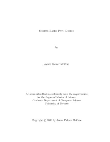
Ryan Schmidt & Karan Singh / Sketch-Based Procedural Surface Modeling and Compositing Using Surface TreesFigure 1: In (a), an extrusion is dragged-and-dropped onto a layered displacement. The green displacement is dragged acrossthe base surface (b), taking the overlapping elements with it. Then the blue edit is stretched (c) and deleted (d). The extrusion isautomatically mapped back onto the green displacement (e), and then interactively dragged back onto the base surface (f).Interactive layered surface modeling has been studied primarily in the context of H-Splines [FB88] and Surface Pasting [BBF94], which are based on hierarchies of spline overlays. In Section 3 we generalize this concept to arbitrarymanifolds, resulting in the Surface Tree. H-Splines are a specific instance of the Surface Tree in which all nodes share aglobal planar parameterization, which tends to result in surface distortion when layers are significantly deformed (Figure 2c). In Section 4 we describe an alternative approach toSurface Tree implementation suitable for meshes and pointset surfaces which does not assume the existance of a globalparameterization, instead relying on a local parameterization at each node, resulting in significantly reduced distortion (Figure 2e). We also describe an efficient proceduralmesh data structure (Section 5), details on our interactivetechniques and sketch-based tools (Section 6), and a discussion of the major limitations of our approach (Section 7).Figure 2: In (a), a displacement “bump” is layered onto aplanar NURBS patch. As in H-Splines, the intrinsic NURBSparameterization stretches as the planar patch is deformed(b), resulting in a deformed displacement (c). Dynamicallycomputing a new local parameterization (d) reduces distortion in the layered edit (e).2. BackgroundSketch-based tools simplify the 3D modeling process by allowing designers to leverage existing artistic ability. Earlysystems such as SKETCH [ZHH96] specified simple shapesby gestural commands. To support free-form modeling, theTeddy system [IMT99] directly inflated sketched 2D curvesinto 3D, an approach adapted in many later works [KH06,Ske07]. Recent profile-based techniques [LGS06] have expanded the range of sketchable shapes. Volumetric sculptingtools [GH91,AWC04,vFTS06] also leverage artistic talent infree-form modeling, and are capable of producing highly detailed models. However, much like physical sculpture, trialand-error iterative design is quite time-consuming.Procedural modeling techniques [Ebe02] such as hierarchical Constructive Solid Geometry, or CSG [RV83], support infinite design refinement, with sketching tools in development [JSC03]. Hierarchical implicit modeling [WGG99,ABGA04] extends CSG with blending and warping operators, and is the basis of the ShapeShop system [SWSJ05].Volumetric spatial deformation [Bar84, SP86, SF98, LJ04] iswidely used in commercial systems [Aut07] and is compatible with CSG-style procedural hierarchies.A key limitation of volumetric techniques is that they donot easily support the intuitive notion of directly manipulating a 3D surface. In contrast, surface deformation techniquesallow the designer to explicitly “push-and-pull” the 3D surface. Variational approaches [WW94, SCOL 04] have become quite popular (see [BS08] for a recent survey). However, introducing a dependency on the surface makes procedural composition non-trivial. The recent FiberMesh system [NISA07] fuses variational techniques with a globalcontrol curve network which can be arbitrarily refined, butlayering and relative definition are not supported.Most procedural surface deformation techniques arebased on the notion of displacement [Coo84]. Originallydeveloped to add surface detail during rendering, displacement mapping has evolved into powerful geometric texturing techniques [PKZ04, Elb05]. Applying geometric textureto locally-parameterized regions is essentially a mesh pasting technique [BMBZ02], and a recent extension [BMPB07]takes exactly this approach. Like our work, these approachesrely on local parameterizations, but none include an underlying dynamic procedural hierarchy.Forsey and Bartel’s seminal Hierarchical Splines [FB88]offered the first truly procedural approach to interactive surface editing. B-Spline detail overlays were layered onto abase patch and encoded using relative offset-vectors. Thesedetail surfaces naturally deformed as underlying layers wereinteractively modified, but the shape of overlays was restricted by the base knot structure. Surface Pasting [BBF94]c The Eurographics Association and Blackwell Publishing 2007.
Ryan Schmidt & Karan Singh / Sketch-Based Procedural Surface Modeling and Compositing Using Surface Treesaddresses this limitation, by allowing arbitrary NURBSpatches to be hierarchically pasted to a base spline patch.Surface pasting was initially developed to quickly approximate layered spline displacement [BF93] by trimming holesin the base spline and simply positioning the “paste” surface in the trimmed hole. Although the result is only “εcontinuous”, it is highly interactive, and has been applied inthe commercial modeling package Houdini [Sid07]. Whilethe initial system was limited to interaction in parameterspace, an interface for directly positioning pasted surfaceshas been developed [CMB97]. However, this “world-space”interaction is ultimately mapped into the parametric domain,exposing a critical limitation of surface pasting - it’s relianceon the base patch parameterization. As underlying patchesare manipulated, the shape of the pasted surface follows the(frequently un-intuitive) distortions that occur in parameterspace [TM98]. The assumption of an underlying global planar parameterization also makes topology change problematic [SM03]. One of the key contributions of our work is todevelop a framework which resolves these limitations.Multiresolution surfaces [ZSS97, LDW97, GKSS02]adapt the H-Spline concept to mesh representations. However, the detail vector hierarchies used in these approachesare derived automatically, and thus lack the user-constructedsemantics found in Surface Pasting and our Surface Trees. Anotable exception is [WM07], in which a dependency graphof sketched subdivision curves and surfaces are inflated into3D volumes. A layered subdivision “skin” blends these volumes together. While this approach is promising, proceduralediting operations are constrained to mesh faces in the current subdivision hierarchy, preventing the intuitive drag-anddrop surface compositing provided by our system.3. Defining Surface TreesHierarchical volumetric modeling techniques [RV83,WGG99] represent complex volumes using trees of composition nodes, with primitive shapes at the leaves. Thepower of these data structures is that any composition nodeor primitive can be trivially replaced with another. In thissection we define an analogous structure for representingdirect surface manipulations - a Surface Tree.At a conceptual level, a surface editing operation replacesa bounded region U on a surface S with an open surface V,where the boundary V coincides with U. Each node N inour Surface Tree simply carries out this replacement:N (S, U , V) (S \ U ) V(1)N can be thought of as a surface compositing operation, andhence a complex surface can be recursively defined by applying nodes to a base surface B:Si 1 Ni (Si , Ui , Vi )S1 N0 (B, U0 , V0 )c The Eurographics Association and Blackwell Publishing 2007.Intuitively, the final output surface is defined by incrementally layering a series of surface patches Vi onto B. Althoughthe recursion above is sequential in nature, any Vi can bedefined by another series of compositions. Hence, a SurfaceTree is a structured binary tree of composition nodes N , witha primary branch that contains B as the initial leaf node, anda series of nested secondary branches which feed into theVi ’s of the primary branch (Figure 3).Figure 3: A surface editing operation locally replaces someregion U of a surface. In a Surface Tree, editing operationscan be applied hierarchically, although secondary branchesmust always output open surfaces to be properly merged.Note that the arguments to N are not independent. S canbe any surface, but it is necessary that U S, and V mustalways be an open surface patch. This implies that only Bcan be a closed surface - all Vi ’s must have an open boundary(and hence so must all secondary branches).In the equations above, we assumed that V U . Theeasiest way to ensure this is to define V E(U ), where Eis a boundary-preserving editing operation. Although arbitrarily complex edits are possible, assume for now that E isa displacement map. The above definition allows V to beprocedurally re-computed if U changes. However, if the designer changes U0 in Figure 3, S1 will change, and U1 willneed to be procedurally re-computed (Figure 4).To ensure maximum flexibility, It is desirable that the recomputation of U be as independent of S as possible. Oneway to accomplish this is to use the tools of Riemanniangeometry [DoC94]. We restrict S to 2-manifolds embeddedin R3 , guaranteeing that any point on S has a local neighbourhood with disc-like topology. S is then covered witha finite atlas of topological discs, referred to as coordinatepatches. A mapping P known as a planar parameterizationexists between each 3D patch and R2 . Given an atlas on S,we can now encode U as a mapping from some 2D region uof the atlas parameter-space to the 3D surface. To simplifythe following exposition, assume that U is contained withina single coordinate patch with parameterization PU . Thenwe can write U(u) PU (u), and rewrite Equation 1 asN (S, u, E) (S \ U (u)) E (U (u))(2)With this formulation, Surface Tree nodes can be procedurally re-computed because the editing region U is encoded
Ryan Schmidt & Karan Singh / Sketch-Based Procedural Surface Modeling and Compositing Using Surface Treesindependent of the current 3D embedding of the input surface S. Instead, it depends on the parameterization. Unfortunately, to build a practical system using arbitrary mesh orpoint-set representations, we must avoid assuming the existence of a global, consistent manifold parameterization aswe have no way of maintaining such a manifold in real-time.This is problematic because we now lack a global embedding space in which to fix the location and shape of eachlayer. In the next section, we describe how we deal with thisissue and implement Surface Trees in our interactive system.ui of each node is embedded in the parameterization computed for some upstream node N j i . Hence, when evaluating Equation 3, we project ui to the seed point pi on thecurrent surface Si to find Ui (see Figure 5).Figure 5: To evaluate node Ni , we first map the anchorpoint ui forward from the upstream node N j i that it is embedded in to the seed point p on the input surface Si . Nextwe compute the editing region U by segmenting from Si anapproximate geodesic disc with radius ri around p, parameterize it, and generate the edited region V. Finally V iscombined with Si \ U to produce the output surface Si 1 .Figure 4: In (a), a displacement is applied to U S tocreate an edited region V. If U is changed, V can be recomputed (b), but how can U be re-computed if S changes(c)? One solution is to write U as a function of a 2D parameterization of S (d). Then if S is deformed, U can bere-computed from the parameterization (e), allowing V tobe applied to the new surface (f).4. Implementing a Surface TreeOur procedural editing operations (Section 6) share acommon foundation, in that they are defined as boundarypreserving modifications to one or more parameterized geodesic discs. Given a seed point p and geodesic radius r,we use Dijkstra’s algorithm [Dij59] to segment an (approximate) geodesic disc from the mesh and parameterize it, creating the editing region U (Figure 6). While many parameterization algorithms are known [SPR06], we use the DiscreteExponential Map [SGW06] because it produces consistentdistortion and is computed in-line with Dijkstra’s algorithm.In Section 3 we described a mathematical formulation of aSurface Tree. In this section we provide details on our implementation, focusing on how the tree is constructed andupdated. To begin, we assume that surfaces S are trianglemeshes, although our approach is also applicable to pointsets and arbitrary polygonal meshes.Following Equation 1, a Surface Tree node N is a procedural operator which applies an editing operation to an inputsurface. In our system, the node operator is defined asSout N (Sin , u, r, E)Figure 6: Given a seed point p on surface Si (a), we segmenta geodesic disc with radius ri (b), parameterize it (c), andapply a deformation (d).(3)where u is a single point embedded in some parameterization, r is the radius of a geodesic disc which contains U (explained below), and E is a mesh editing operation.Our basic approach is as follows. The primary branch ofour Surface Tree begins with a base mesh B and incrementally applies procedural editing operations:Si 1 Ni (Si , ui , ri , Ei )S1 N0 (B, u0 , r0 , E0 )Editing regions U are defined as parameterized trianglepatches which approximate geodesic discs of radius r centered at seed points p. These per-node parameterizations arere-used to approximate a global manifold - the anchor point4.1. Node Anchoring and UpdatingAs noted, we lack a global atlas which can be used to fixthe position of each editing layer. We do, however, have aparameterized support region computed for each editing operation. Hence, we can embed the seed point p of an edit asan anchor point ui in the existing parameterization of someupstream node N j . This creates a dependency between Niand N j (Figure 7), so our Surface Tree is not strictly a tree,but rather a highly structured dependency graph [Hae88].This anchor point approach inherently avoids the ambiguous case where an editing region U overlaps the boundariesc The Eurographics Association and Blackwell Publishing 2007.
Ryan Schmidt & Karan Singh / Sketch-Based Procedural Surface Modeling and Compositing Using Surface TreesSi 1 N (Si , ui , ri , Ei )p Pro jectToSur f ace(ui )U GeodesicDisc(p, ri )PU ExpMapParameterization(U)Si 1 (Si \ U) Ei (U , PU )Algorithm 1: Computing the output of a Surface Tree node.the anchor points using a surface-constrained handle. This3D widget, which also incorporates components for rotatingand scaling [SGW06], allows edits to be quickly “draggedand-dropped”, re-ordered, and deleted.Figure 7: Three bumps are layered onto a sphere. In (a)the parameterized edit regions for Nodes 1 and 2 are shown.Node 3 is anchored to Node 1 because it’s seed point doesnot lie within Node 2’s support (b). The potential ambiguitydue to boundary overlaps in (c) is avoided because only theseed points are embedded in the parameterizations (d).of several underlying layers, as in Figure 7c. Since the anchor is a single point, it can be embedded in the parameterspace of a single input node. This embedded anchor can always be mapped forward through the tree to unambiguouslyfix the position of the seed point using the algorithm listed inFigure 8. Note that as a parameterized point u has both 2Dand 3D coordinates, here usage is determined by context.Interactive actions often require dynamic re-anchoring ofnodes, for example if the user drags a seed point outside thesupport region of it’s anchor node. Hence, each time nodeN is explicitly moved by the designer, we automatically reanchor it’s seed point in the “nearest” input node using Algorithm 2. We implement the inverse mapping E 1 in thisalgorithm by finding the triangle containing p and interpolating u from the triangle uv-coordinates.u FindAnchorPoint( p Ni )k i 1u E 1k (p)while u / Uku E 1k (u)k k 1Algorithm 2: Finding the anchor point for a surface point.Figure 8: The algorithm on the left maps the seed point uifor the rightmost red node in Figure 7b from it’s embeddingin the green node to the output surface of the blue node.With these encoding and anchoring schemes in place, wecan give an algorithmic description of how Equation 3 isimplemented (Algorithm 1). The steps in this algorithm areequivalent to the visualization in Figure 5. Note that this algorithm only explicitly handles the primary branch. In ourimplementation, secondary branches generate arbitrary openmeshes which are layered onto the primary branch using ageometric texturing editing operation, effectively “pasting”the output of the secondary branch onto the surface.4.2. Surface Tree ManipulationOne advantage of our surface tree construction is that layerscan be dynamically manipulated simply by interacting withc The Eurographics Association and Blackwell Publishing 2007.Algorithm 2 is also called during tree manipulation. Before removing node Ni , Algorithm 2 is used to transfer anyseed points anchored in Ni to some input node N j i , after which Ni can be safely removed by connecting it’s inputNi 1 to it’s output Ni 1 . Similarly, to insert Nk between Niand Ni 1 , any seed points anchored to Ni lying within thenew support of Nk are “pushed forward” to Nk .Although it is not possible to perfectly anticipate theuser’s intent in all cases, we find that our approach gives theexpected behavior most of the time. Essentially, if node A isanchored to node B, then when B is dragged across the surface, A will “stick” to it. This emulates the layer “grouping”found in other layer-based tools such as Illustrator [Ado07].Automatic anchoring will only link A to B if the user explicitly drags A on to B - anchoring does not change if Bis dragged underneath A. Note that the “layer order” is implicitly defined by the dependency structure of the SurfaceTree, the user must explicitly re-order layers to, for example, move a small edit at layer n on top of a larger editat layer n 1. Surface Pasting tried to avoid this situationby automatically re-ordering layers [BBF94], but there aremany cases where this behavior can produce un-expected results, and it diverges from 2D layer-based interfaces [Ado07]where layer ordering is explicitly under user control.
Ryan Schmidt & Karan Singh / Sketch-Based Procedural Surface Modeling and Compositing Using Surface Trees5. A Procedural Mesh Data StructureOur system operates on triangle meshes. To simplify notation, we will consider a mesh to be a simple list of triangles.Each node in our Surface Tree takes an input mesh Sin , modifies it, and outputs a new mesh Sout . As the edit region Uis defined with respect to Sin , each node is dependent on it’sinput mesh, making a full tree update O(N) in the numberof nodes. This can be reduced by storing all intermediatemeshes - then if the designer edits node i, only nodes j ineed be evaluated. Unfortunately, the overhead of copyingand storing the mesh at each node is overwhelming.Since our edits are locally supported, it is possible to construct a more efficient data structure for representing intermediate meshes. First we define two abstract mesh editingoperations - Mask and Weld. Mask simply removes the triangle subset U S from S (Figure 9b), and, recalling ourprevious notation V E(U), Weld inserts V into the holecreated by Mask (Figure 9d):Mask(S, U) S \ UWeld(S, V) S VAs previously noted, a procedural edit E must preserve theboundary of U, to avoid introducing “cracks” between S andV. Hence, assuming that U and V have been computed, theseoperators can be chained together:Sout Weld( Mask(Sin , U ) , V )In our system, the geometry of S is accessed through iterators, so Mask and Weld can be implemented as iteratorswhich either skip certain triangles (Mask) or iterate overmultiple meshes (Weld). With this approach, a node nevermodifies Sin , but rather generates an iterator which masquerades as a manifold mesh by transparently hiding the trianglesin U and inserting V. Clearly, Mask and Weld can be appliedrecursively, creating a procedural mesh data structure.In practice, our mesh is not simply a list of triangles, butan efficient vertex/edge/face manifold representation. Thiscomplicates the implementation of Weld, as it must transparently re-write the incoming and outgoing indices of boundary vertices and edges, to preserve the outward appearanceof a manifold mesh. Note that Mask and Weld can be appliedto point set surfaces, where the implementation is simplifiedbecause the explicit boundary re-writing is unnecessary.Since Mask and Weld do not copy or modify Sin , they arehighly efficient even when applied to large meshes. They do,however, add overhead to mesh iterations, which can limitinteractivity as the surface tree grows. Hence, we have foundit useful to occasionally cache a full copy of Sin at a node.This cache simply copies the geometry produced by the incoming Mask/Weld iterators into a single manifold mesh,which is much more efficient to iterate over. In particular, ifthe user selects Ni for editing, we cache the output of Ni 1to ensure that interactive feedback is as fast as possible.Figure 9: The Mask operator creates a hole in S by hidingtriangles in the editing region U (a) during mesh iterations(b). Edits E generate V by copying and modifying U (c),which often involves mapping to uv-space for re-meshing.Finally, Weld synthesizes a manifold mesh by transparentlycombining Mask(S, U ) and V during iteration (d).6. Surface Tree Creation and InteractionOur Surface Tree editor is implemented as an extensionto the ShapeShop modeling system [SWSJ05]. Similar toother sketch-based modeling tools, ShapeShop’s workflowinvolves a mixture of sketch-based and traditional interfaces.A suggestion-list interface [IH01] allows the user to create and modify a variety of edits based on sketched curves.Other parameters are controlled using 2D and 3D widgets.Visualizing and interacting with the existing Surface Treeis a difficult task, one which we have only begun to explore.To select an existing node for manipulation, the user clickson it’s support region. If multiple nodes lie under the cursor,repeated clicking cycles through them. The selected node ishilighted, and all overlapping layers are rendered transparently (Figure 11b). As the user manipulates the selection,overlapping nodes are dynamically re-evaluated and rendered. We limit re-evaluation of overlapping layers to maintain interactivity, the full tree update is deferred until the userfinishes with the manipulation (Figure 11d).We now briefly describe the editing tools available in oursystem. As previously noted, these tools operate on parameterized approximate geodesic discs segmented from themesh, which correspond to the decal parameterizations of[SGW06]. Generally, edits take one or more user-sketchedstrokes as additional parameters. Since our strokes are represented by spline curves, and displacement offsets by func-Figure 11: The support region of an edit node is highlightedwhen it is selected (a), and all overlapping layers are rendered as transparent (b). Computation of layers in (c) canbe deferred as the user manipulates an underlying layer (d)to maintain a minimum interactive frame-rate.c The Eurographics Association and Blackwell Publishing 2007.
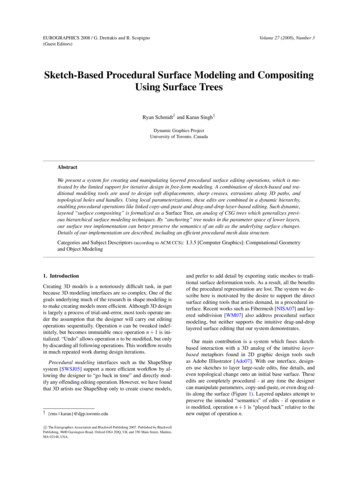
Ryan Schmidt & Karan Singh / Sketch-Based Procedural Surface Modeling and Compositing Using Surface TreesFigure 10: Our system supports a variety of editing operations. Drawing a closed loop on the surface specifies a region fordisplacement with varying falloff strength (a). Surface curves also can specify displacement (b), with an optional height curve(inset strokes have been shifted). Arbitrary open meshes can be dynamically stitched into the mesh (c), creating a watertightsurface (d). Edges of sketched creases are also inserted into the mesh, to preserve sharpness (e). Displacements can be pulledalong 3D curves, and optional profile curves produce arbitrary generalized cylinders (f). Multiple surface patches can also beconnected to create dynamic holes and handles (g).tional scalar fields, our edits can be computed at arbitraryresolution, allowing high-quality surfaces to be generated.6.1. Sketched DisplacementDisplacement mapping [Coo84] is one of the simplesttypes of procedural surface manipulation, and displacementpainting tools [LF03] have become popular in commercialsystems [Pix07]. Although here we take a sketch-based approach, our techniques would be a useful addition to thesesystems, as displacements painted into procedural decals canbe easily moved or later modified.In our system, arbitrary surface regions can be displacedby sketching a closed loop around the desired area (Figure 10a). The displacement offset is based on a smoothedapproximation to the 2D distance field of the region contour [PKZ04, SWSJ05], allowing for a continuous range oftransition smoothness. Sharp transition edges are created byinserting the sketched polyline directly into the mesh usingconstrained Delaunay triangulation [She96].Sketched open surface curves can also be used to displace the surface, with an optional second curve beingused to modulate the displacement height (Figure 10b). Thewidth can also be tied to height, producing a variable-widthdisplacement reminiscent of the area-proportional inflationused in the Teddy system [IMT99]. The scalar displacementmaps are created by accumulating radial 2D fields at regular intervals along the sketched curve. The combined fieldis defined as maxi (hi max(1 (di /ri )2 )3 , 0)), where di isthe distance to the origin of the ith field, ri is it’s radius, andhi the height. To create sharp creases, we remove the squareon the (d/r)2 term, producing a sharp, “inverted” falloff region. To accurately reproduce the crease, we directly insertthe sketched curve into the mesh, again using Delaunay triangulation in parameter space (Figure 10e).c The Eurographics Association and Blackwell Publishing 2007.Displacements can also be extended along curved paths(Figure 10f), supporting the construction of larger-scale edits. The path can be dynamically edited by re-sketching, andan optional second curve can be used to define a profilefunction, turning the displacement into a flexible generalized cylinder. Note that the profile width must be blendedwith the orignal width near the base of th
as Adobe Illlustrator [Ado07]. With our interface, design-ers use sketches to layer large-scale edits, fine details, and even topological change onto an initial base surface. These edits are completely procedural - at any time the designer d-its along the surface (Figure 1). Layered updates .