Transcription
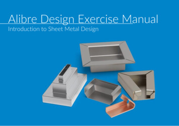
Alibre Design Exercise ManualIntroduction to Sheet Metal Design
CopyrightsInformation in this document is subject to change without notice. The software described in this documents is furnished under a licenseagreement or nondisclosure agreement. The software may be used or copied only in accordance with the terms of those agreements. No partof this publication may be reproduced, stored in a retrieval system, or transmitted in any form or any means electronic or mechanical,including photocopying and recording for any purpose other than the purchaser’s personal use without the written permission of Alibre, LLC.Alibre, LLC1750 N Collins BlvdSte. 212Richardson, TX 75080U.S.Awww.alibre.com 2018 Alibre, LLC. All rights reserved.Alibre and the Alibre logo are registered trademarks in the United States and/or other countries.
Creating a Tool Holder
11. Open a new Sheet Metal Part workspace from Alibre Design's Home window.
1321. Click on the Sheet Metal tab in the ribbon.2. Click on the XY Plane in the Design Explorer.3. Click on the Activate 2D Sketch icon.
11.Select the Grid options.
1231.Enable the Display Grid option if it is unchecked.2.If necessary, change the values to .500 or .25 inch for X, Y, and Z.3.Press the OK button.
121.Click on the dropdown menu of Rectangle tool on the Sketch Figures tab in the ribbon.2.Select the Rectangle by Center from the List.
211. Position the mouse cursor near the Origin point. Roll the mouse wheel forward to zoom in. Theview of the work area should be similar to the screen capture.2. Position the mouse cursor over the Origin point. The point's color and cursor tool tipchanges confirm that the mouse cursor is positioned properly. CLICK AND RELEASE to createthe center point of the Rectangle.
11. Move the mouse cursor horizontally to the right, input a dimension of 1.500 Inches for thehorizontal distance from the center of the rectangle to its edge, and then hit Enter.
1321.2.Click on Dimension.Select the left or right vertical line of Rectangle, then click on the workspace locationwhere you want to place the dimension and input a value of 6.000”.3. Click on the green checkmark or press the Enter key on the keyboard.
11.Completed rectangle view of the work area should be similar to the image above.
111.Click on the dropdown menu of Circular Arc tool on the Sketch Figures tab in the ribbon.2.Select the Circular Arc-Start, End, Radius option from the List.
3121.Move the mouse cursor over the top-right sketch node on the rectangular sketch (1.50”to the right of the origin & 3.00” above the Origin). Click and release to create theStart point of the Arc.2.Move the mouse cursor over the top-left sketch node on the rectangular sketch.Click and release to create the End point of the Arc.3.Move the mouse cursor in an upward direction until the tangential constraintsymbols appear. Click and release to complete the Arc.
121.Click on the Trim tool on the Sketch Tools tab in the ribbon.2.Click on the top horizontal sketch line to execute the Trim.
11. Click Yes on the pop-up window to complete the process.
211. Completed Sketch view of the work area should be similar to the screen capture.2. Click on the Circle tool on the Sketch Figures tab in the ribbon.
121.Move the mouse cursor close to the position shown (4.00” over the Origin). Click andrelease to create the Center point of the Circle.2.Enter a value of 0.25” for the circle’s diameter, and then hit Enter on your keyboard toapply the value.
14231. Click on Dimension.2. Click on the center point of the circular sketch you just created.3. Click on the node point referenced by Callout “3” in the image above.4. Enter a dimension of 1.00” and hit Enter.
121. Use the Rectangle sketch tool to create a rectangular sketch similar to what is shownabove.2. Use the Dimension tool and apply a width of .200” and a length of 2.000” to therectangular sketch.
211. Use the Dimension tool to position the rectangular sketch accordingly so that it is centeredhorizontally on the workspace. Use a value of 0.500” for the distance from the left mostvertical sketch line on the canvas to the left vertical sketch line of the rectangular sketch.2. Use the Dimension tool and apply a 0.900” distance from the top horizontal line of therectangular sketch to the node point.
11. Use the Circular Arc – Start, End, Radius sketch tool and the Trim tool to edit theRectangular sketch into an Obround sketch as shown in the image above.
121.Click on the Dropdown menu of the Pattern tool on the Sketch Tools section ofthe ribbon.2.Select Linear Pattern.
121.In the Linear Repeat dialog box, click on the Select Objects field.2.Select the sketch lines to be patterned
111.In the Linear Repeat dialog box, click on the box named Linear Path.2.Select the highlighted edge as the Pattern Direction.
1231.In the Linear Repeat dialog box, Increase the Instances to 9.2.In the Linear Repeat dialog box, Change the Spacing to 0.500”.3.Click Ok and then click Deactivate Sketch on the ribbon.
1231. Click on the Tab in Base Features section in the ribbon.2. Confirm that Sketch 1 appears in the Tab; entry box.3. Click OK.
11.Confirm similar results for the Tab operation.
1231.Click on the Flange in Sheet Metal Tools section in the ribbon.2.Click the Edge box inside the Dialog3.Click on the edges shown to select them.
1231. Move the mouse cursor over the point on the flange preview & click and drag until the measurementindicator in the Flange window displays 1.500. CLICK AND RELEASE to complete the Flanges.2. Select the Adjacent option under Alignment in Main tab of Flange dialog box.3. Select the Tab under the Length option in Main tab of Flange dialog box.
123451.2.3.4.5.Click on the Corners tab in the Flange dialog box.Click on the checkbox and Enable the Miter.Select the Corner Closed under the Miter in Corners tab of Flange dialog box.Input a value of .008” for the Gap widthClick Apply.
121.Confirm similar results for the Flange operation.2.Click on the Close.
1321.Click on Flange in Sheet Metal Tools section in the ribbon.2.Click on the Edge box in the dialog.3.Position the mouse cursor over the inside edge of the left flange, and then click to select it.
21341. Enter a value of 3.000 inches for the leg length in the dialog.2. Select the Inside option under Alignment in Main tab of Flange dialog box.3. Select the Tab under Length in the Main tab of Flange dialog box.4. Click Apply then Close.
11.Confirm similar results for the Flange operation.
1231.2.3.4.Click on Flange in Sheet Metal Tools section in the ribbon.Click the Edge box in the dialog.Click on all four inside edges of the bottom of the sheet metal partSet the length value to .715”
123451.2.3.4.5.Click on the Corners tab in the Flange dialog box.Click on the checkbox and Enable the Miter.Select Corner Relief under Miter in the Corners tab of Flange dialog box.Confirm the Gap width value in the Flange dialog box is 0.008 inches.Click Apply.
121.Confirm similar results for the Flange operation.2.Click on the Close.
211.Right-click on the front face of the sheet metal part2.Select the Activate 2D Sketch from the Menu or Press Ctrl K on Keyboard.
1231.2.3.Click on the Project to Sketch tool and then click on the top edge of the front face of themodel.Choose the Create reference figure option in the dialogClick OK
121. Click on the Line tool, then hover your cursor over the center point of the referenceline.2. Create the sketch lines as shown.
11. Use the Circular Arc-Start, End, Radius to create an arc with a radius of.625” to close the sketch.
13241.2.3.4.Click on the Mirror tool and select the sketch lines you just created except for the verticalline, and populate the Figures to Mirror box of the Mirror dialogClick on the Mirror Axis box of the mirror figure dialog.Select the vertical line of the sketch for the Mirror axis field in the dialog.Click OK.
2341.2.3.4.Use the Trim tool to remove the center line. Click Deactivate Sketch (Not shown).Click on the Cut tool in the Sheet Metal Tools section on the Ribbon.Select the To Depth option from the dropdown menu of Type in the Cut Dialog Box.Click OK.
211.Confirm similar results for the Cut operation.2.Right-click on the front face of the part and select the Activate 2D Sketch from the Menu orPress Ctrl K on Keyboard.
3121.2.3.Select the Rectangle tool in the Sketch Figures section on the Ribbon.Sketch a rectangle with a Length of 2.000” and a Width 0.250“, whose tophorizontal sketch line is one inch above the bottom of the part.Click Deactivate Sketch.
124351.2.3.4.5.Click on the Dimple tool in Sheet Metal Tools section in the Ribbon.Confirm that the sketch you just created appears in the Sketch field of the Dimple dialog.Input a 1 degree draft angle in the Draft angle field of the dimple dialogEnable the Checkbox named Cut Out Material.Click OK.
211.Right click anywhere on the Sheet Metal part.2.From the pop-up menu select Color Properties.
21431. Click on Color in the Color Properties dialog.2. Select a bright orange color in the Color dialog box by clicking on one of the colored tiles inthe Basic colors area.3. Click OK in the Color dialog box.4. Click OK in the Color Properties dialog box.
11.Confirm similar results for the Color Properties operation.
1231.Click the Unbend tool, and select the back face of the part as the Fixed Face.2.Click on the Select All Bends option.3.Click OK
121.Confirm the results of the Unbend tool.2.Blue color lines show the Bending Pattern.*Notice that the Pattern represents the bends as it would on the physical object.
121.Click on the Rebend tool.2.Click Select all unbent bends, and click OK
11. Confirm the results of the Rebend.
11.Click on the Flat Pattern in the Sheet Metal Tools tab in the Ribbon.
1121.Confirm similar results for the Flat Pattern operation.2.Blue color lines show the Bending Pattern.* Notice that the Pattern represents the bends as it would on the physical object.
11.2.3.Click Flat Pattern again to return the sheet metal part to its closed state.Save this Sheet Metal file to your preferred location with the name: Tool Holder (notshown).Close the Sheet Metal workspace (not shown).This concludes the Tutorial.
1. Use the Dimension tool to position the rectangular sketch accordingly so that it is centered horizontally on the workspace. Use a value of 0.500" for the distance from the left most vertical sketch line on the canvas to the left vertical sketch line of the rectangular sketch.