Transcription
INSTALLATION INSTRUCTIONSFan CoilsFEM4X, FSM4X, FSU4X, FXM4XThese instructions must be read and understood completely before attempting installation.Safety Labeling and Signal WordsDANGER, WARNING, CAUTION, andNOTEThe signal words DANGER, WARNING,CAUTION, and NOTE are used to identify levels ofhazard seriousness. The signal word DANGER isonly used on product labels to signify an immediatehazard. The signal words WARNING, CAUTION,and NOTE will be used on product labels andthroughout this manual and other manuals that mayapply to the product.DANGER Immediate hazards which will result insevere personal injury or death.WARNING Hazards or unsafe practices whichcould result in severe personal injury or death.CAUTION Hazards or unsafe practices whichmay result in minor personal injury or product orproperty damage.Signal Words in ManualsThe signal word WARNING is used throughout thismanual in the following manner:WARNINGWARNING!The signal word CAUTION is used throughout thismanual in the following manner:CAUTION!Signal Words on Product LabelingSignal words are used in combination with colorsand/or pictures on product labels.NOTE Used to highlight suggestions which willresult in enhanced installation, reliability, oroperation.TABLE OF CONTENTSIntroduction . . . . . . . . . . . . . . . . . . . . . . . . . . . . . . . . . . . . 2Location . . . . . . . . . . . . . . . . . . . . . . . . . . . . . . . . . . . . . . . 2Clearances and Dimensions . . . . . . . . . . . . . . . . . . . . . 3Heater Packages . . . . . . . . . . . . . . . . . . . . . . . . . . . . . . . 4Position Unit . . . . . . . . . . . . . . . . . . . . . . . . . . . . . . . . 4 8Air Ducts . . . . . . . . . . . . . . . . . . . . . . . . . . . . . . . . . . . . . . 9Electrical Connections . . . . . . . . . . . . . . . . . . . . . . 9 13Refrigerant Tubing . . . . . . . . . . . . . . . . . . . . . . . . . . . . . 14Refrigerant Metering Device . . . . . . . . . . . . . . . . . . . . 14Condensate Drains . . . . . . . . . . . . . . . . . . . . . . . . . . . . 15Accessories . . . . . . . . . . . . . . . . . . . . . . . . . . . . . . . . . . 16Sequence of Operation . . . . . . . . . . . . . . . . . . . . . . . . . 17Start up Procedure . . . . . . . . . . . . . . . . . . . . . . . . . . . . 17Care and Maintenance . . . . . . . . . . . . . . . . . . . . . . . . . 17Airflow Performance . . . . . . . . . . . . . . . . . . . . . . . 18 21!WARNINGPERSONAL INJURY, AND/OR PROPERTY DAMAGEHAZARDFailure to carefully read and follow this warning couldresult in equipment malfunction, property damage,personal injury and/or death.Installation or repairs made by unqualified personscould result in equipment malfunction, property damage, personal injury and/or death.The information contained in this manual is intendedfor use by a qualified service technician familiar withsafety procedures and equipped with the propertools and test instruments.Installation must conform with local building codesand with the National Electrical Code NFPA70 currentedition.R 410A Quick Reference Guide . . . . . . . . . . . . . . . . . 22496 01 5402 02 April 2011
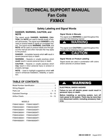
INSTALLATION INSTRUCTIONSFan Coils: FEM4X, FSM4X, FSU4X, FXM4XINTRODUCTIONModels FEM4X, FSM4X, and FXM4X are designed formaximum flexibility and can be used for upflow, horizontal leftor right, and downflow applications (accessory kit requiredfor downflow or horizontal right).Model FSU4X is designed for upflow installation, and can befield modified for downflow and horizontal left or rightapplications (accessory kits required for downflow orhorizontal).FEM4X and FXM4X models are available for system sizes1 1/2 5 tons (18,000 60,000 BTUH) nominal coolingcapacity.FEM4X and FXM4X models use an ECM motor and have afactory installed and appropriately sized hard shut off TXVmetering device and are for R 410A refrigerant ONLY.FSM4X and FSU4X models use a PSC motor and have afactory installed and appropriately sized hard shut off TXVmetering device and are for R 410A refrigerant ONLY.Factory approved electric heater packages are available insizes 3kW through 30kW. See Product Specificationliterature for available accessory kits.FSM4X, and FSU4X models are available for system size 5ton (60,000 BTUH) nominal cooling capacity.LOCATIONSelect the best position which suits the installation siteconditions. The location should provide adequate structuralsupport, space in the front of the unit for service access,clearance for return air and supply duct connections, spacefor refrigerant piping connections and condensate drain lineconnections. If heaters are being installed make sureadequate clearance is maintained from supply duct work.See Clearances in Figure 1.NOTE: Internal filter can be accessed from separate filterdoor. If the filter can NOT be easily accessed, a remote filteris recommended. Refer to ACCA Manual D for remote filtersizing.If the unit is located in an area of high humidity, nuisancesweating of casing may occur. On these installations a wrap of2” (51mm) fiberglass insulation with a vapor barrier isrecommended.Failure to maintain proper clearances could result in personal injury, death, and/or property damage.2!WARNINGFIRE HAZARDWhen heaters are installed, maintain clearances fromcombustible materials as specified on unit rating plate.Do not use plastic lined or combustible flexible ductingwithin 36 inches (1m) of the supply end of the fan coil.496 01 5402 02
INSTALLATION INSTRUCTIONSFan Coils: FEM4X, FSM4X, FSU4X, FXM4XFigure 1Clearances and Unit Dimensions( OPENING)FBAEHGCD(SERVICE ACCESS)38 11 82( OPENING)REQUIRED CLEARANCES ALL MODELS (inches)All SidesNoFrom Supply DuctHeatersAll SidesWithFrom First 3 feet of Supply Duct to CombustiblesHeatersFrom Supply Duct to Combustibles after 3 3/4B11111111111111496 01 5402 02FEM4X Inches (English)CDEF19-13/16 12-5/16 22-1/16 X, FSU4X Inches (English)CDEF19-13/16 22-11/16 22-1/8 24-11/16FXM4X Inches -13/16 22-11/16 22-1/16 24-11/1619-13/16 22-11/16 22-1/16 00420048006000A400400489489489578578FEM4X mm (SI Metric)BCDEFG279 503 313 560 364 533279 503 397 560 448 533279 503 397 560 448 533279 503 486 560 537 533279 503 486 560 537 533279 503 486 560 537 533279 503 486 560 537 610279 503 489 560 537 533FSM4X, FSU4X mm (SI Metric)BCDEFG279 503 576 562 627 610FXM4X mm (SI Metric)BCDEFG279 503 397 560 448 533279 503 397 560 448 533279 503 486 560 537 533279 503 486 560 537 533279 503 486 560 537 533279 503 576 560 627 610279 503 576 560 627 135712611261135715033
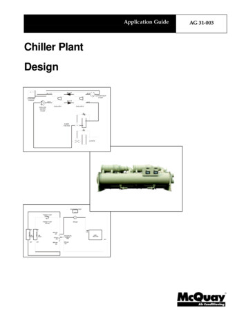
INSTALLATION INSTRUCTIONSFan Coils: FEM4X, FSM4X, FSU4X, FXM4XHEATER PACKAGESFactory approved, field installed, UL listed heater packagesare available from the equipment supplier. See unit ratingplate for a list of factory approved heaters. Heaters that arenot factory approved could cause damage which would notbe covered under the equipment warranty.POSITION UNITUnit can stand or lie on floor, or hang from ceiling or wall.Allow space for wiring, piping, and servicing unit.CAUTION!PROPERTY DAMAGE HAZARDFailure to follow this caution may result in propertydamageA. UPFLOW INSTALLATIONIf return air is to be ducted through a floor, set unit on floorover opening and use 1/8 to 1/4 inch thick (3 to 6 mm thick)fireproof resilient gasket between duct, unit, and floor.Side return is a field option on slope coil models. Cut openingper dimensions shown in Figure 2. A field supplied bottomclosure is required.A field fabricated auxiliary drain pan, with a separatedrain is REQUIRED for all installations over a finished living space or in any area that may be damagedby overflow from a restricted main drain pan. In somelocalities, local codes require an auxiliary drain panfor ANY horizontal installation.Figure 2Upflow InstallationPOWER ENTRYOPTIONSFIELD SUPPLIEDSUPPLY DUCTLOW VOLTENTRYOPTIONSFRONT SERVICE CLEARANCE60 model 24” (610 mm)SLOPE COIL UNITSFEM4XMODEL SIZE182430A COILUNITSUPFLOW/DOWNFLOWSECONDARY DRAIN1 1/2”UPFLOW/DOWNFLOWPRIMARY DRAIN19”A2-1/2”(64mm)FIELD MODIFIEDSIDE RETURNLOCATION FORSLOPE COILUNITS ONLYUPFLOW/DOWNFLOWSECONDARY DRAINUPFLOW/DOWNFLOWPRIMARY DRAIN412" (305mm)17" (432mm)17" (432mm)19" (483mm)35(483mm)ASLOPE COIL UNITSFXM4XMODEL SIZE182430A17" (432mm)17" (432mm)19" (483mm)FIELD SUPPLIEDRETURN PLENUM496 01 5402 02
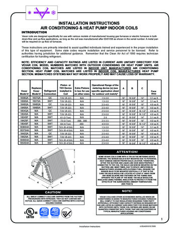
INSTALLATION INSTRUCTIONSFan Coils: FEM4X, FSM4X, FSU4X, FXM4XAt completion of the downflow installation, caulk around thevertical pan fitting to door joint to retain low air leakperformance of the unit.B. DOWNFLOW INSTALLATION!CAUTIONPRODUCT OR PROPERTY DAMAGE HAZARDFailure to follow this caution may result in product orproperty damageThe conversion of the fan coil to downflow requiresspecial procedures for the condensate drains on bothA coil and Slope coil units. The vertical drains havean overflow hole between the primary and secondarydrain holes. This hole is plugged for all applicationsexcept downflow, and must be used for downflow.Failure to follow instructions could result in personalinjury or product and property damage.In this application, field conversion of the evaporator coil isrequired using accessory Downflow Kit along with anaccessory Base Kit. Set unit on floor over opening and use1/8” to 1/4” thick fireproof resilient gasket between duct, unit,and floor. Refer to installation instructions packaged withaccessory kit. See Product Specification literature for kit partnumbers.During the conversion process, removed the plastic capcovering the vertical drains only and discard.NOTE: Gasket kit number (EBAC01GSK) is also required forall downflow applications to maintain low air leak/low sweatperformance.C. HORIZONTAL INSTALLATIONUnit must NOT be installed with access panels facing up ordown. Access panels must only face to the side.FEM4X, FSM4X, and FXM4X models are factory built forhorizontal left installation (refer to Figure 3 and Figure 4).They can be field converted to horizontal right (accessoryGasket Kit required, see Product Specification literature forpart number). Refer to Figure 5 and Figure 6.FSU4X models require accessory kits for any horizontalinstallation (see Product Specification literature for requiredaccessory kits).NOTE: When suspending unit from ceiling, dimples in casingindicate suitable location of screws for mounting metalsupport straps.NOTE: For optimum condensate drainage performance inhorizontal installations, unit should be leveled along its lengthand width.Remove the plug from the overflow hole and discard.Figure 3Horizontal Left Application (Slope Coil) (FXM4X factory configuration)A COILHORIZONTAL YDRAINFRONT SERVICE CLEARANCE(FULL FACE OF UNIT)18 48 models 21” (533mm)60 model 24” (610mm)SECONDARYDRAINLOW VOLTENTRYOPTIONS1 3/4” (45mm)FILTER ACCESSCLEARANCEPOWERENTRYOPTIONS496 01 5402 02PRIMARYDRAIN5
INSTALLATION INSTRUCTIONSFigure 4Fan Coils: FEM4X, FSM4X, FSU4X, FXM4XHorizontal Left Application (A Coil) (FEM4X, FSM4X, and FXM4X factory configuration)ACOILBRACKETFACTORY SHIPPEDHORIZONTAL LEFTAPPLICATIONCOILSUPPORTRAILBCDRAIN PANSUPPORTBRACKETCOILBRACKETHORIZONTALDRAIN PANPRIMARY DRAINHORIZONTAL LEFTAIR SEALASSEMBLYREFRIGERANTCONNECTIONSHorizontal Right Conversion of Units With Slope Coils1. Remove blower and coil access panel and fitting panel(refer to Figure 5).2. Remove coil mounting screw securing coil assemblyto right side casing flange.3. Remove coil assembly.4.Lay fan coil unit on its right side and reinstall coil assemblywith condensate pan down (refer to Figure 5).SECONDARY DRAINHORIZONTAL LEFT5. Attach coil to casing flange using coil mounting screwpreviously removed.6. Align holes with tubing connections and condensatepan connections, and reinstall access panels andfitting panel. After brazing, make sure liquid andsuction tube grommets are in place to prevent airleaks and cabinet sweating.Horizontal Right Conversion Applications (Slope Coil) (FXM4X)Figure 5COIL MOUNTINGSCREWBLOWERASSEMBLYCOIL SUPPORT RAILSLOPE COILDRAINPANPRIMARY DRAINREFRIGERANTCONNECTIONSSECONDARY DRAIN6496 01 5402 02
INSTALLATION INSTRUCTIONSFan Coils: FEM4X, FSM4X, FSU4X, FXM4XHorizontal Right Conversion of Units With A Coils1. Remove blower and coil access panel and fitting panel(refer to Figure 6).2. Remove coil mounting screw securing coil assemblyto right side casing flange.3. Remove coil assembly.4. Lay fan coil unit on its right side and reinstall coilassembly with condensate pan down (refer toFigure 6).5. Remove horizontal drain pan support bracket from coilsupport rail on left side of unit and reinstall on coilsupport rail on right side of unit.6. Convert air seal assembly for horizontal right (refer toFigure 6).a. Remove air seal assembly from coil by removing 4screws.b. Remove coil drip flanges from A coil and reinstall onright side of coil (same side as horizontal drain pan).c. Remove filler plate (A) and install air splitter (B) inplace of filler plate.d. Install filler plate (A) as shown in horizontal rightapplication.e. Remove condensate troughs (C) and install onopposite tube sheets.f. Install hose onto plastic spout.7. Install horizontal pan on right side of coil assembly.8. Slide coil assembly into casing. Be sure coil bracket oneach corner of vertical pan engages coil support rails.9. Reinstall 2 snap in clips to correctly position andsecure coil assembly in unit. Be sure clip with largeoffsets is used on right side of unit to secure horizontalpan.10. Remove 2 oval coil access panel plugs and reinstallinto holes on left side of coil access panel and fittingpanel.11. Remove insulation knockouts on right side of coilaccess panel12. Reinstall access fitting panels, aligning holes withtubing connections and condensate pan connections.Be sure to reinstall metal clip between fitting panel andvertical condensate pan.13. After brazing, make sure liquid and suction tubegrommets are in place to prevent air leaks and cabinetsweating.Horizontal Right Conversion Applications (A Coil)Figure 6AREFRIGERANTCONNECTIONSAIR AILCOILBRACKETBCDRAIN TALDRAIN PANPRIAMRY DRAINHORIZONTAL RIGHTSECONDARY DRAINHORIZONTAL RIGHT496 01 5402 027
INSTALLATION INSTRUCTIONSD. MANUFACTURED HOUSING AND MOBILE HOMEAPPLICATIONSFan Coils: FEM4X, FSM4X, FSU4X, FXM4XFigure 71. Fan coil unit must be secured to the structure usingfield supplied hardware.2. Allow a minimum of 24 inches (610mm) clearancefrom access panels.3. Recommended method of securing for typicalapplications:a. If fan coil is away from wall, attach pipe strap to topof fan coil using No. 10 self tapping screws. Anglestrap down and away from back of fan coil, removeall slack, and fasten to wall stud of structure using5/16” lag screws. Typical both sides of fan coil.Mobile Home or Manufactured Housing Applications4” (102mm) MAXSECURE FAN COIL TO STRUCTUREUNIT AWAY FROM WALLPIPE STRAP(TYPICAL BOTH SIDES)ORUNIT AGAINST WALL11/8” (3mm) INCH THICK ANGLEMOUNTING BRACKET(TYPICAL BOTH SIDES)b. If fan coil is against wall, secure fan coil to wall studusing 1/8” (3mm) wide right angle brackets. Attachbrackets to fan coil using No. 10 self tapping screwsand to wall stud using 5/16” lag screws (refer toFigure 7).DOWN FLOWBASE KITSECURE UNIT TO FLOORANGLE BRACKET OR PIPE STRAP4” (102mm) MAXNOTE: Modular units can be disassembled andcomponents moved separately to installation areafor reassembly. This process accommodates smallscuttle holes and limiting entrances to installationsites (refer to Figure 8).Figure 8Removal of Brackets onModular UnitsBLOWER BOX2 SCREWS2 SCREWSREAR CORNERBRACKET2 SCREWSCOIL BOX8496 01 5402 02
INSTALLATION INSTRUCTIONSFan Coils: FEM4X, FSM4X, FSU4X, FXM4XAIR DUCTSConnect supply air duct over the outside of 3/4” flangesprovided on supply air opening. Secure duct to flange usingproper fasteners for type of duct used, and seal duct to unitjoint.Use flexible connectors between duct work and unit toprevent transmission of vibration. When electric heater isinstalled, use heat resistant material for flexible connectorbetween duct work and unit at discharge connection. Ductwork passing through unconditioned space must beinsulated and covered with vapor barrier.Duct work Acoustical TreatmentMetal duct systems that do not have a 90 degree elbow and10 feet of main duct before first branch takeoff may requireinternal acoustical insulation lining. As an alternative, fibrousduct work may be used if constructed and installed inaccordance with the latest edition of SMACNA constructionstandard on fibrous glass ducts. Both acoustical lining andfibrous duct work shall comply with National Fire ProtectionAssociation as tested by UL Standard 181 for Class 1 airducts.ELECTRICAL CONNECTIONSFEM4X (1 1/2 to 4 ton), FSM4X and FSU4X Fan Coilmodels utilize an electronic fan board which has a low voltagecircuit protective fuse (5 amp), fan motor speed tap terminal(SPT), and time delay relay (TDR). To disable the TDRfeature, snip the jumper wire JW1 (refer to Figure 9).Make all electrical connections in accordance with the NECand any local codes or ordinances that may apply. Usecopper wire only. The unit must have a separate branchelectric circuit with a field supplied disconnect switch locatedwithin sight from and readily accessible from the unit.FEM4X (5 ton) and FXM4X Fan Coil models have a low voltagecircuit protective fuse (3 amp) inline on the wire harness. Speedselections are made at the fan motor by selecting taps 1, 2, or 3with the Blue wire. The motor is pre programmed with thetime delay circuit on some of the speed taps. (See Section D)NOTE: When a pull out type disconnect is removed from theunit, only the Load side of the circuit is de energized. TheLine side remains live until the main (remote) disconnect isturned off.Before proceeding with electrical connections, make certainthat supply voltage, frequency, phase, and circuit ampacity areas specified on the unit rating plate. See unit wiring label forproper field high and low voltage wiring.!WARNINGELECTRICAL SHOCK or UNIT DAMAGE HAZARDFailure to follow this warning could result in personalinjury, death, and/or unit damage.If a disconnect switch is to be mounted on unit, selecta location where drill and fasteners will not contactelectrical or refrigeration components.Figure 9!WARNINGELECTRICAL SHOCK HAZARDFailure to follow this warning could result in personalinjury or death.Turn off the main (remote) disconnect device beforeworking on incoming (field) wiring .Incoming (field) wires on the line side of the disconnect found in the fan coil unit remain live, even whenthe pull out is removed. Service and maintenance toincoming (field) wiring cannot be performed until themain disconnect switch (remote to the unit) is turnedoff.Fan Coil Printed Circuit BoardFSM4X, FSU4XFEM4X (1 1/2 to 4 ton)HK61EA0105JW1496 01 5402 02JW19
INSTALLATION INSTRUCTIONSFan Coils: FEM4X, FSM4X, FSU4X, FXM4XA. LINE VOLTAGE CONNECTIONSB. 24V CONTROL SYSTEMFan Coils installed without electric heat require the use of afactory authorized Power Plug Kit (accessory part numberEBAC01PLG). This kit provides the electrical connectionsnecessary to supply the unit with 208/230V power whenelectric heat is not present. For units without electric heat:Connection to Unit1. Connect 208/230V power leads from field disconnectto yellow and black stripped leads on Power Plug(accessory part number EBAC01PLG).2. Connect ground wire to unit ground lug.3. When installing an electric heater, remove and discardpower plug (if equipped) from fan coil and connectmale plug from heater to female plug from unit ctions.)Wire low voltage in accordance with wiring label on theblower (also refer to Figure 10 through Figure 14). Use 18AWG color coded, insulated (35 C minimum) wire to makethe low voltage connections between the thermostat, theunit, and the outdoor equipment. If the thermostat is locatedmore than 100 feet from the unit (as measured along the lowvoltage wire), use 16 AWG color coded, insulated (35 Cminimum) wire. All wiring must be NEC Class 1 and must beseparated from incoming power leads. Refer to outdoor unitwiring instructions for additional wiring recommendations.Heater StagingThe controls are factory circuited for single stage operation(refer to Figure 11 and Figure 12). When 2 stages aredesired, cut W3 at the W2 wire nut, strip, and reconnectaccording to the thermostat kit instruction (refer to Figure 13 outdoor thermostat optional). When 3 stages are desired,cut the W2 wire nut off and discard. Strip W2, W3, and E, andreconnect according to the thermostat kit instructions (referto Figure 14 outdoor thermostats optional).!CAUTIONUNIT OPERATION HAZARDFailure to follow this caution may result in improperproduct operation.If W2, W3, and E on any 3 stage heater (18, 20, 24, or30kW) are individually connected as with outdoorthermostats or any other situation emergency heatrelay must be used. If relay is not used, blower maynot operate when heaters are energized.10496 01 5402 02
INSTALLATION INSTRUCTIONSFigure 10Wiring Layout Air ConditioningUnit (Cooling Only)FANCOILWIRINGTHERMOSTATRGWFan Coils: FEM4X, FSM4X, FSU4X, FXM4XFigure 13Wiring Layout Heat Pump Unit(Cooling and 2 Stage Heat withOne Outdoor UJumperBRNAIR COND.YFigure T PUMP(CONTROL)RGRYBRNCWHTJumperBLUCEVIOWiring Layout Heat Pump Unit(Cooling and 1 Stage Heat with NoOutdoor Thermostat)FANCOILWIRINGREDAIR COND.WODTS1ODTS2YTHERMOSTATOOYYHEAT PUMP(CONTROL)RGRYBRNW2WHTJumperBLUEWiring Layout Heat Pump Unit(Cooling and 2 Stage Heat withTwo Outdoor Thermostats)GRYYCYTHERMOSTATBRNGYREDVIOROFigure 14BLUFigure 12OWiring Layout Air ConditioningUnit (Cooling and 1 Stage Heat)FANCOILWIRINGWBLUCYCWHTW2VIORGRYGWHTHEAT PUMP(CONTROL)CVIOWOOYY496 01 5402 0211
INSTALLATION INSTRUCTIONSFan Coils: FEM4X, FSM4X, FSU4X, FXM4XTransformer InformationTransformer is factory wired for 230V operation. For 208Vapplications, disconnect the black wire from the 230V terminalon transformer and connect it to the 208V terminal (refer toFigure 15).Figure 15Transformer ARYC. GROUND CONNECTIONS!WARNINGELECTRICAL SHOCK HAZARDFailure to establish uninterrupted or unbrokenground could result in personal injury and/or death.According to NEC, ANSI/NFPA 70, and local codes,the cabinet must have an uninterrupted or unbrokenground in order to minimize potential for personal injury or death if an electrical fault should occur. Theground may consist of electrical wire or metal conduitwhen installed in accordance with existing electricalcodes. If conduit connection uses reducing washers,a separate ground wire must be used.FEM4X (5 ton) and FXM4X models: fan speed is selectedat the motor connector. Units with or without electric heatersrequire a minimum CFM. Refer to the unit wiring label toensure that the fan speed selected is not lower than theminimum fan speed indicated.SPEED TAP SELECTION AT MOTOR CONNECTORTap 1Low90 sec off delayTap 2Medium90 sec off delayTap 3High90 sec off delayTap 4Electric Heat †0 sec off delayTap 5Max ‡0 sec off delay† Electric heat airflow is same CFM as Tap 3, but with 0sec off delay.‡ For high static applications, see Airflow PerformanceTables for max airflow.To change motor speeds disconnect the BLUE fan lead frommotor connector terminal #2 (factory default position) andmove to desired speed tap; 1, 2, 3, or 5.Speed taps 1, 2, and 3 have a 90 second blower off timedelay pre programmed into the motor. Speed tap 4 is usedfor electric heat only (with 0 second blower time delay) andthe WHITE wire should remain on tap 4. Speed tap 5 is usedfor high static applications, but has a 0 second blower timedelay pre programmed into the motor (see AirflowPerformance Tables for actual CFM for each tap). Also, seeFigure 16 for motor speed selection location.NOTE: In low static applications, lower motor speed tap shouldbe used to reduce possibility of water being blown off coil.NOTE: Use UL listed conduit and conduit connectors forconnecting supply wire(s) to unit to obtain proper grounding.Grounding may also be accomplished by using grounding lugsprovided in control box.D. MINIMUM CFM AND MOTOR SPEED SELECTIONUnits with or without electric heaters require a minimum CFM.Refer to the unit wiring label to ensure that the fan speedselected is not lower than the minimum fan speed indicated.FEM4X models (1 1/2 to 4 ton): fan speed selection is done atthe fan motor. To change motor speeds, reposition wire at fanmotor speed terminals labeled 1 2 3 (refer to Figure 16).FSM4X and FSU4X models: fan speed selection is done atthe fan relay on the electronic fan board. To change motorspeeds, disconnect fan lead used on relay terminal (SPT) andreplace with motor speed lead desired (refer to Figure 17).Save insulating cap and place on motor lead removed fromrelay.NOTE: In low static applications, lower motor speed tap shouldbe used to reduce possibility of water being blown off coil.All units have 2 or 3 motor speed taps. Low speed (red or 1) isdesigned for mismatch outdoor unit applications. Mediumspeed (blue or 2) is designed for straight matchedoperations. High speed (black or 3) is used with high externalstatic duct situations on straight matched systems.12496 01 5402 02
INSTALLATION INSTRUCTIONSFan Coils: FEM4X, FSM4X, FSU4X, FXM4XFEM4X and FXM4X Motor SpeedSelectionFigure 16Figure 17FSM4X, FSU4X Fan Coil Relay andSpeed Tap TerminalPCBFAN RELAYSINGLE SPADEINSULATING CAP (2)1 2 3 4 5MOTOR SPEEDTAP LEADSSpeed Taps may be located on motor,or on plug close to motor.COMMON YELLOWSPEED TAPTERMINALWRAPPERFAN DECK1 2 3 4 5CL G NL11S018496 01 5402 0213
INSTALLATION INSTRUCTIONSFan Coils: FEM4X, FSM4X, FSU4X, FXM4XREFRIGERANT TUBINGSize and install refrigerant lines according to informationprovided with outdoor unit. Route refrigerant lines to the fancoil in a manner that will not obstruct service access to theunit or removal of the filter.1. Find the liquid tube grommet in the small parts bagand slide it onto the liquid refrigerant line (fieldline set).2. Remove the lower door. Remove the tubing plate (withsuction tube grommet) and slide the plate withgrommet onto the refrigerant lines (field line set), awayfrom braze joints.3. Remove rubber plugs from coil stubs using a pullingand twisting motion. Hold coil stubs steady to avoidbending or distorting.4. Wrap TXV and nearby tubing with a heat sinkingmaterial such as a wet cloth.5. Fit refrigerant lines into coil stubs. Wrap a heat sinkingmaterial such as a wet cloth behind braze joints.6. Braze using a Sil Fos or Phos copper alloy.7. After brazing, allow joints to cool. Slide tubing plateback into place and position grommets around suctionand liquid tubes to ensure air seal.!CAUTIONPRODUCT DAMAGE HAZARDFailure to follow this caution may result in productdamage.Braze with Sil Fos or Phos copper alloy on copper to copper joints and wrap a wet cloth around rear offitting to prevent damage to TXV.REFRIGERANT METERING DEVICEFEM4X, FSM4X, FSU4X, FXM4XThese Fan Coils have a factory installed hard shut off TXVdesigned only for use with R 410A refrigerant. Use only withoutdoor units designed for R 410A.TXV is factory set and not field adjustable.!CAUTIONPRODUCT DAMAGE HAZARDFailure to follow this caution may result in productdamage.This Fan Coil has a hard shut off TXV metering device. A compressor Hard Start Kit is REQUIRED in allapplications where the matching outdoor unit has asingle phase reciprocating compressor.14496 01 5402 02
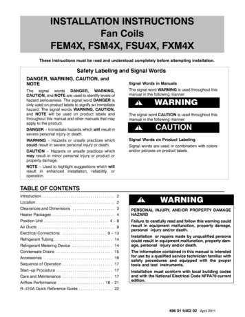
INSTALLATION INSTRUCTIONSFan Coils: FEM4X, FSM4X, FSU4X, FXM4XCONDENSATE DRAINSUnit is provided with primary and secondary 3/4” (19mm)NPT drain connections. Refer to Figures 2, 3, 4, 5, and 6 toidentify the primary and secondary locations. To preventproperty damage and achieve optimum drainageperformance, BOTH primary and secondary drain linesshould be installed and include properly sized condensatetraps (refer to Figure 18). Factory approved condensatetraps are available (accessory part number EBAC01CTK).Figure 18UNIT2” MIN (51mm)To connect drainlines, the drain connection knock outs mustbe removed. Use a knife to start the opening near the tab andusing pliers, pull the tab to remove the knock out. Clean theedge of the opening if necessary. After drain fittings areinstalled, caulk the seam between the fitting and the cover toretain the low leak rating of the unit.It is recommended the PVC fittings be used on the plasticcondensate pan. Do not over tighten. Finger tighten plus1 1/2 turns. Use pipe dope, to ensure proper seal.Install traps in the condensate lines as close to the coil aspossible (refer to Figure 20), but avoid blocking filter accesspanel.Recommended Condensate Trap2” MIN (51mm)Figure 19Insufficient Condensate TrapInstall drain lines below the bottom of the drain pan and pitchthe drain lines down from the coil at least ¼ inch per foot ofrun (6mm per 0.3m). Horizontal runs over 15 feet (5m) longmust also have an anti s
FEM4X and FXM4X models are available for system sizes capacity. FSM4X, and FSU4X models are available for system size 5 ton (60,000 BTUH) nominal cooling capacity. FEM4X and FXM4X models use an ECM motor and have a factory installed and appropriately sized hard shut off TXV metering device and are for R 410A refrigerant ONLY.