Transcription
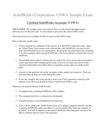
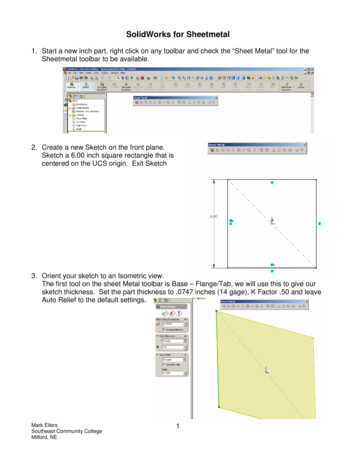
SolidWorks for Sheetmetal1. Start a new inch part, right click on any toolbar and check the “Sheet Metal” tool for theSheetmetal toolbar to be available.2. Create a new Sketch on the front plane.Sketch a 6.00 inch square rectangle that iscentered on the UCS origin. Exit Sketch3. Orient your sketch to an Isometric view.The first tool on the sheet Metal toolbar is Base – Flange/Tab, we will use this to give oursketch thickness. Set the part thickness to .0747 inches (14 gage), K Factor .50 and leaveAuto Relief to the default settings.Mark EilersSoutheast Community CollegeMilford, NE1
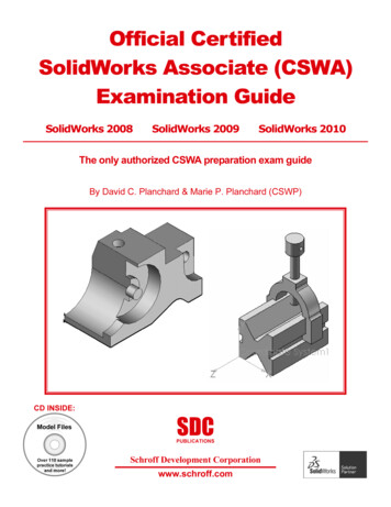
4. If you noticed there is no library of material for the K Factorand you were not prompted for the bend radius. The KFactor can be customized by Excel spreadsheets and thebend radius can be set after the part has thickness byediting the Sheet Metal feature in the browser bar. Set thebend radius to .125 inch.5. Next we are going to add an EdgeFlange to one of the sides of thebase part. We will add a 90degree X 2.50 inch flange, createthe settings so after the flange iscomplete the total measurement ofthe flange will be 2.50 inches andthe original length of 6.00 incheswill increase by the sheet metalthickness.6. Create another Edge Flange on an edgeperpendicular to the last flange. We wantto add this flange as a 90 degree X 2.50inch with the settings set so the finalflange will also be 2.50 inches tall,however; on this flange we don’t want the6.00 inch base dimension to increase withthe addition of material.Mark EilersSoutheast Community CollegeMilford, NE2
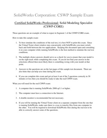
7. The next tool on theSheet Metal toolbar isMiter Flange. We willcreate a Miter Flangeon the combination ofthe first flange that weapplied and the basefeature. Create a newsketch on this face.Sketch a line that is.500 inch long from theoutside edge. Exitsketch.8. Select the Miter Flange button and the size of the flange is selected from the sketched .500inch line. The first edge is also selected from the edge that the line was sketched from.Select the outsideedge of the bend andthe far side edge ofthe original basefeature.We will keep thematerial inside of thepart. Turn on trim sidebends and leave thegap distance to .02inch.Set the start offset to1.00 inch and the endoffset to .500 inch.Mark EilersSoutheast Community CollegeMilford, NE3
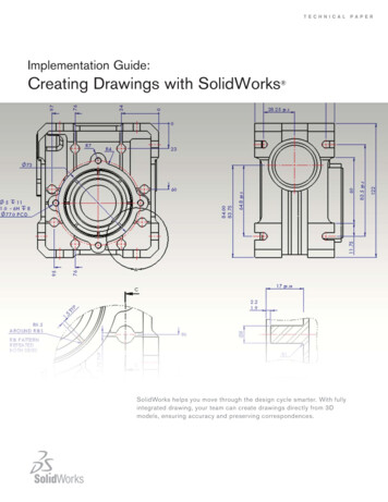
Finished part up to this point.The Auto Relief creates the cuts at a transition pointbased upon a ratio of the sheetmetal thickness.9. The next tool on the Sheetmetal toolbar isHem. We are going to create a hem on theflanged side of the part that we started theMiter Flange on. Create a Rolled hem onthe outside edge with the material inside.Roll the hem 270 degrees and give the heman inside radius of .125 inches.10. The next tool on the Sheetmetal toolbarSketched Bend. On the .500 face ofthe long side of the Mitered Flange wewill create a sketch for the SketchedBend.Mark EilersSoutheast Community CollegeMilford, NEis4
11. Once the sketched is complete select the Base –Flange/Tab tool on the Sheetmetal toolbar, this willgive the last sketch the correct thickness basedupon prior settings.12. Next we need to create a sketch onthis tab that will start and stop on thefar edges of the tab. The sketchedline can either be perpendicular tothe edges or at a selected angle. Iplaced my line .375 inches from themiter flange. Exit sketch and selectthe Sketched bend tool. The firstrequirement is selected the FixedFaces, then you can set the bendangle requirements.13. Next we will explore the Jogged tool.Create a sketch on the same face as thelast step. Exit sketch, select the Base –Flange/Tab tool and give this new tabthickness.Mark EilersSoutheast Community CollegeMilford, NE5
14. Create another new sketch on this taband sketch a line that will be used forthe Jog tool. Dimension as shown andexit sketch.15. Select the Jogged tool.The first requirementis to select the fixedface. Then you canset the jog offset, thedimension position thejog position and theangle of the jog.Example part up to this pointMark EilersSoutheast Community CollegeMilford, NE6
16. Add a 2.50 inch Edge Flangeon the side of the base part thatwe haven’t used yet.Set the flange position tomaterial inside and select thetrim side bends option.Now we have a sheetmetalcorner that we can use theClosed Corner tool on.17. Select the Closed Corner tooland select the face that you would like to extend and the corner type that you prefer.Finished cornerMark EilersSoutheast Community CollegeMilford, NE7
18. Next add louvers and patternGo to the Design Library and make the Forming ToolsFolder the current folder by using the context menu.19. Drag and Drop the louver to the surface that youwould want the forming punch to come from. (The firstsurface that the forming punch would contact)Apply the Geometric Constraints and Dimensions for your requirement. And finishMark EilersSoutheast Community CollegeMilford, NE8
20. Pattern the louvers.We want 7 louvers that have aspacing of .75 inches.21. Now we will use the Unfold tool to unfold the jogged tab. Select the fixed face and thenselect the two folds that need to be unfolded.22. Next we will create an opening onthe tab that we just flattened out.Create a sketch on the face of thetab, sketch the geometry, constrainand dimension. Exit sketch.Mark EilersSoutheast Community CollegeMilford, NE9
23. Using the Extrude Cut on theSheetmetal toolbar we will cutout the last sketch, linking thesheet metal’s thickness to thedepth of the cut.24. Now we can refold the tabby using the Fold tool on theSheetmetal tool bar,returning the tab back to itsoriginal shape.Mark EilersSoutheast Community CollegeMilford, NE10
25. Now we can create a flat sheet metal layout of the part by selecting the Flatten button onthe Sheet Metal toolbar.26. Now we can use the Corner-Trim relief options to add a corner relief. Set the ReliefOptions to .1875, select the edge in the corner and set the Relief style to Circular.Mark EilersSoutheast Community CollegeMilford, NE11
Now let’s use SolidWorks to create a sheet metal transition.27. Start a new inch part and create a newSketch on the front plane. Constrain thegeometry and dimension as shown.The rectangular geometry on the right side of the sketch is used to create and center a gap inthe sketch geometry. Finish sketch and Exit Sketch.Mark EilersSoutheast Community CollegeMilford, NE12
28. Create a new offsetWorkplane 4.00 inches abovethe Front Plane.29. On this new work plane create a new Sketch.Constrain the geometry and dimension asshown.OriginExit SketchMark EilersSoutheast Community CollegeMilford, NE13
30. On the Sheet Metal toolbarthe Lofted Bend tool is nowavailable. Select the LoftedBend tool and then selectthe first sketch profile andthen select the top sketchprofile. Set the materialthickness to .0747 inches(14 gage).Reminder: It doesmatter where you select theseprofiles. Select them close totheir profile gaps.Mark EilersSoutheast Community CollegeMilford, NE14
31. Select Flatten on the Sheet Metal toolbar and the sheetmetal transition that we just createdwill turn into a flat pattern layout.Mark EilersSoutheast Community CollegeMilford, NE15
SolidWorks for Sheetmetal 1. Start a new inch part, right click on any toolbar and check the “Sheet Metal” tool for the Sheetmetal toolbar to be available. 2. Create a new Sketch on the front plane. Sketch a 6.00 inch square rectangle that is centered on the UCS origin. Exit Sketch 3. Orient your sketch to an Isometric view. The first tool on the sheet Metal toolbar is Base – Flange/Tab .