Transcription
13Surface ModelingLearning ObjectivesAfter completing this chapter you will be able to: Create an Extruded Surface. Create a Revolved Surface. Create a Sweep Surface. Create a Blended Surface. Create a Swept Blend Surface. Create a Helical Sweep Surface. Create a Surface by Blending the Boundaries. Create a Surface using Variable Section Sweep. Create surfaces using Style environment. Understand surface editing tools.Logonwww.cadcim.comChapter for free download. Logon to www.cadcim.com for more informationChapter
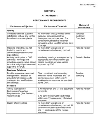
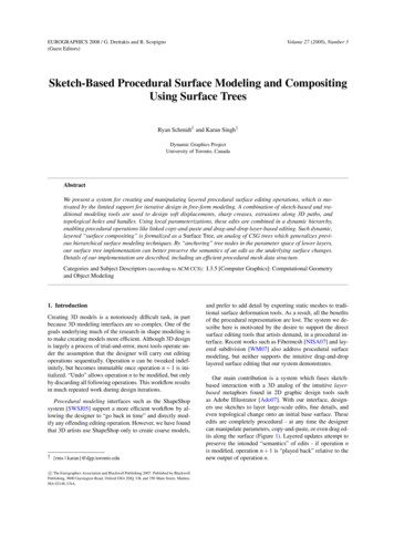
13-2Pro/ENGINEER Wildfire for Designers: F09/04SURFACE MODELINGLogonwww.cadcim.comChapter for free download. Logon to www.cadcim.com for more informationSurface models are a type of three-dimensional (3D) models with no thickness. These modelsare widely used in industries like automobile, aerospace, plastic, medical, and so on.Surface models should not be confused with thick models, that is, models having mass properties.Surface models do not have thickness whereas thick or solid models have a user-defined thickness.In Pro/ENGINEER, the surface modeling techniques and feature creation tools are the same asthat used in solid modeling. A solid model of any shape that is created can also be created usingthe surface modeling techniques. The only difference between the solid model and the surfacemodel will be that the solid model will have mass properties but the surface model will not.Sometimes, complex shapes are difficult to create using solid modeling. Such models can beeasily created using surface modeling and then the surface model can be converted into thesolid model. It becomes easy for a person to learn surface modeling if he is familiar with solidmodeling feature creation tools.CREATING SURFACES IN Pro/ENGINEER WILDFIRE 2.0In Pro/ENGINEER Wildfire 2.0, a sketch can be toggled between a solid model and a surfacemodel. The two tool buttons that are used to toggle between the solid feature and a surfacefeature are available on dashboards.Creating an Extruded SurfaceTo create an extruded surface, choose the Extrude Tool button from the Base Featurestoolbar. The Extrude dashboard is displayed as shown in Figure 13-1.Figure 13-1 The Extrude dashboardIn this dashboard, the Extrude as solid button is selected by default. Select theExtrude as surface button to extrude the sketch and create a surface model. All theattributes that are related to a solid model and that were discussed in Chapter 3 are samefor a surface model also. Some examples of these attributes are sketch plane, both-side orone-side extrusion, depth of extrusion, and so on.A surface model can be extruded with capped ends or with open ends. Figure 13-2 shows theopen end surface model and Figure 13-3 shows the capped end surface model. Rememberthat to create the capped end surface model, the sketch should be a closed loop. Otherwise,a surface can be created with the open sketch.To create a surface with capped ends, select the Capped Ends check box in the Options slideup panel.
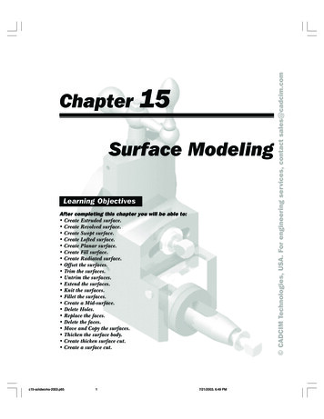
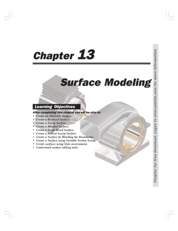
13-3Figure 13-2 Surface with open endsFigure 13-3 Surface with capped endsCreating a Revolved SurfaceTo create a revolved surface, choose the Revolve Tool button from the Base Features toolbar.The Revolve dashboard is displayed as shown in Figure 13-4. This feature creation tool works inthe same way as in the case of solid modeling.Figure 13-4 The Revolve dashboardThe Revolve as solid button is selected by default; choose the Revolve as surfacebutton to create a revolve surface. You can create a revolved capped end surface or anopen end surface. The Capped End check box in the Options slide-up panel isavailable only when the sketch is closed and the angle of revolution is less than360-degrees. Figure 13-5 shows the open end revolve surface and Figure 13-6 shows the cappedend revolve surface.Figure 13-5 Revolved surface with open endsFigure 13-6 Revolved surface with capped endsLogonwww.cadcim.comChapter for free download. Logon to www.cadcim.com for more informationSurface Modeling
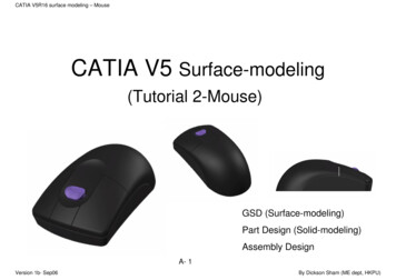
13-4Pro/ENGINEER Wildfire for Designers: F09/04Logonwww.cadcim.comChapter for free download. Logon to www.cadcim.com for more informationCreating a Sweep SurfaceTo create a sweep surface feature, choose Insert Sweep Surface from the menu bar. TheSWEEP TRAJ menu is displayed. The method to create a surface sweep feature is the same asthat to create a solid sweep feature. To create a solid sweep feature, refer to Chapter 7. Theadditional option of capping the ends that were available in the Extrude and Revolve options isalso available in the Sweep option.Figures 13-7 and 13-8 show the sweep surfaces with the open and closed ends respectively.Figure 13-7 Sweep surface with open endscreated using a closed sketchFigure 13-8 Sweep surface with capped ends createdusing a closed sketchCreating a Blended SurfaceTo create a surface blend, choose Insert Blend Surface from the menu bar. The BLENDOPTS menu is displayed. The method to create a blended surface is the same as that to create asolid blend. To create a solid blend feature, refer to Chapter 7. Blended surfaces can be withopen ends or capped ends. Figure 13-9 shows the blended surface with open ends and Figure 13-10shows the blended surface with capped ends.Figure 13-9 Blended surface with open endsFigure 13-10 Blended surface with capped ends
Surface Modeling13-5To create a swept blend surface, choose Insert Swept Blend Surface from the menu bar.The BLEND OPTS menu is displayed. The method to create a swept blend surface is the samethat to create a solid swept blend feature. To create a solid swept blend feature, refer to Chapter 8.Figure 13-11 shows the swept blend with open ends and Figure 13-12 shows the swept blend withcapped ends.Figure 13-11 Swept blend surface with openendsFigure 13-12 Swept blend surface with capped endsCreating a Helical Sweep SurfaceTo create a surface helical sweep, choose Insert Helical Sweep Surface from the menu bar.The Surface dialog box and the ATTRIBUTES menu is displayed. The method to create ahelical sweep surface feature is the same as that to create a solid helical sweep feature. For moreinformation on creating solid helical sweep features, refer to Chapter 8. Figure 13-13 shows thehelical sweep surface with open ends and Figure 13-14 shows the helical sweep surface withcapped ends.Tip: If you want to create a surface blend with capped end, you need to create a closedsketch. Pro/ENGINEER does not accept an open sketch for a capped end blend surface.To create a surface blend with capped ends and keeping the sketch open can also bedone. For this purpose, select the Open Ends option and then draw an open sketch.Give the blend depth and create the blended surface. Now, redefine the surface featureand modify the open ends attribute to capped ends. Choose OK from the SURFACEdialog box. The blended surface with the capped ends is created. This is also true withother features like extrude, revolve, sweep, and so on.Creating a Surface by Blending the BoundariesTo create a surface by blending the boundaries, datum curves, or points, choose theBoundary Blend Tool button from the Base Features toolbar. The Boundary Blenddashboard is displayed as shown in Figure 13-15 and you are prompted to selectLogonwww.cadcim.comChapter for free download. Logon to www.cadcim.com for more informationCreating a Swept Blend Surface
Logonwww.cadcim.comChapter for free download. Logon to www.cadcim.com for more information13-6Pro/ENGINEER Wildfire for Designers: F09/04Figure 13-13 Helical sweep surface with openends created using an open sketchFigure 13-14 Helical sweep feature with cappedends created using the closed sketchtwo or more curve chains to define a blended surface. The use of this dashboard are discussednext.Figure 13-15 The Boundary Blend dashboardCurves tabWhen you choose the Curves tab, the slide-up panel is displayed. Choose a curve from thegraphics window; the curve is highlighted in red as shown in Figure 13-16. At the two ends ofthe curve, T 0 is displayed, an arrow is attached to the curve. When you modify the value of T,which is by default 0, to some higher value then the curve is extended from that end. PressCTRL left mouse button to select the second curve; the second curve also gets highlighted.Both the selected curves are numbered as per the sequence of selection. The surface is created asshown in Figure 13-17.Figure 13-16 Curves selected to blendFigure 13-17 Boundary blend surface
Surface Modeling13-7Now, invoke the Curves slide-up panel and select 2 Chain from the First direction collector;the slide-up panel is displayed as shown in Figure 13-18. In the slide-up panel, the Move upand Move down buttons are available, which can change the order of selection of the curves.The Closed blend check box is used to close the surfaces.Figure 13-18 Curves slide-up panelTip: To delete the curves from the collector, right-click the collector and choose theRemove all option from the shortcut menu that is displayed.Figure 13-19 shows the surface created after selecting the three curves and Figure 13-20 showsthe surface that is closed by selecting the Closed blend check box.Figure 13-19 Surface created after selecting thecurvesFigure 13-20 Surface created after closing itThe Second direction collector in the Curves slide up panel is used to select curves in thesecond direction. The second direction curves are usually drawn in a direction other than thatof the first direction. The Figure 13-21 shows the first and second direction curves andFigure 13-22 shows the surface created after selecting the curves shown in Figure 13-21.Logonwww.cadcim.comChapter for free download. Logon to www.cadcim.com for more informationThe collector present below the Curves tab shows 2 Chains. This collector represents the Curvestab and the number of curves selected in the first direction are displayed in this collector.
Logonwww.cadcim.comChapter for free download. Logon to www.cadcim.com for more information13-8Pro/ENGINEER Wildfire for Designers: F09/04Figure 13-21 Datum curvesFigure 13-22 Surface created by selecting the curvesin two directionsCreating a Surface Using Variable Section SweepTo create a surface by variable section sweep, choose Insert Variable Section Sweep from themenu bar. The Variable Section Sweep dashboard is displayed. To learn more about VariableSection Sweep, refer to Chapter 8. The procedure to create a variable section sweep feature orsurface is the same as was discussed in Chapter 8.Figure 13-23 shows the trajectories and section that are used to create the variable sectionsweep surface. You have an option to keep the ends open or capped. This option is availablein the Options slide-up panel.Figure 13-23 Variable section sweep surface with open ends
Surface Modeling13-9Style is an environment available in Pro/ENGINEER that is used to draw free style curves andcreate surfaces by joining them. The surfaces created using the Style environment are calledSuper features. This is because these features can contain any number of curves or surfaces.The Style surfaces can be joined with the Pro/ENGINEER surfaces. They can have theparent-child relationship among themselves and as well as with Pro/ENGINEER features.To enter the Style environment, choose the Style Tool available in the Base Featurestoolbar or choose Insert Style from the menu bar. Figure 13-24 shows the appearanceof the Style environment.Figure 13-24 Style environmentStyle Tools ToolbarFigure 13-25 shows the Style Tools toolbar available in the Style environment. The toolsavailable in this toolbar are discussed next.Select ButtonThis button is used to select the surfaces, curves, planes, and so on in the Styleenvironment. If you are in middle of a feature creation tool you can choose the Selectbutton to exit that tool.Logonwww.cadcim.comChapter for free download. Logon to www.cadcim.com for more informationCREATING SURFACES USING STYLE ENVIRONMENT OFPro/ENGINEER WILDFIRE 2.0
Logonwww.cadcim.comChapter for free download. Logon to www.cadcim.com for more information13-10Pro/ENGINEER Wildfire for Designers: F09/04Figure 13-25 Style Tools toolbarSet the active datum plane ButtonThis button is used to select the datum plane on which the drawing or the editingoperation needs to be performed. The datum plane that you select is highlighted by amesh.Create Internal Datum Plane ButtonThis button is chosen by selecting the black arrow on the right of the Set the activedatum plane button. When you select the arrow, the flyout is displayed. Choose theCreate Internal Datum Plane button to create an internal datum plane in the Styleenvironment. When you choose this button the DATUM PLANE dialog box is displayed. Thisdialog box is used to create a datum plane in a similar procedure that was discussed in Chapter 4.The datum planes are named as DTM1, DTM2, and so on.It should be noted that the datum planes created using this button are displayed in the graphicswindow only when you are in the Style environment. Once you exit the Style environment, thedatum plane becomes invisible. Any feature created in the Style environment is displayed in theModel Tree as a Style feature.Create Curves ButtonThis button is used to draw curves. When you choose this button, the Curve dashboardis displayed as shown in Figure 13-26.Figure 13-26 The Curve dashboardThe options in this dashboard are discussed next.
13-11Free Radio ButtonWhen the Curve dashboard is displayed, the Free radio button is selected by default. Theprompt in the Message Area reads “Click to define points for the curve (SHIFT to snap)”.To create curve, click on the screen. A yellow point is displayed at the location where youclicked. Now, again click to define the second point of the curve. The two points arejoined. When you click to define the location of the third point, you will notice that thecurve that you are drawing is defined by a spline. After defining the points, press themiddle mouse button to create the curve. While specifying a point if you press the SHIFTkey then the point is snapped to the entity already present on the screen.Remember that the curve drawn using the Free option is created on the active datum plane.To draw a 3D curve you need to snap the point on the existing entity. You can also draw a 3Dcurve by choosing the Toggle showing all views and one view full-size button from theStyle toolbar. When you choose this button, the display is turned into four windows. InPro/ENGINEER, this type of display is called a 4-view display mode. The four views showthe top, default, right-side, and front views. You can select a point in one window and thenselect the second point in the other window. By specifying points in different windows, the3D curve can be drawn. To switch back to the single window display mode, choose theToggle showing all views and one view full-size button.Tip: To undo the last operation, choose the Undo button from the Style toolbar. Theshortcut for undo is CTRL Z.Planar Radio ButtonThis radio button when selected allows you to create the curve on the datum plane that ishighlighted by the mesh. This datum plane is called the active plane. The active plane canbe selected before invoking the Curve dashboard by choosing the Set the active datumplane button.Tip: Using the Planar option, you can project a point of an existing entity on theactive datum plane. This can be done by selecting the point on the entity using theSHIFT key. The selected point is projected on the active datum plane.COS Radio ButtonThis radio button is used to draw curves on surfaces. The points that you define on a surfaceare constrained to that surface. When you click to define the location of the first point of thecurve, the point is placed. Now, this surface is selected and the points placed hereaftershould lie on the same surface. If you click outside this surface then the point is not placedon the surface. After the curve is drawn, press the middle mouse button. The red curve isconverted to a white curve indicating that the curve is completed. The curve drawn on thesurface is the child of the surface.Control Points Check BoxWhile drawing the curve, if this check box is selected, then while editing the curve thecontrol points are displayed.Logonwww.cadcim.comChapter for free download. Logon to www.cadcim.com for more informationSurface Modeling
13-12Pro/ENGINEER Wildfire for Designers: F09/04Logonwww.cadcim.comChapter for free download. Logon to www.cadcim.com for more informationEdit curves ButtonThis button is used to edit the curves that are created as style features. When you choosethis button the Edit curve dashboard is displayed and you are prompted to select acurve. When you select a curve to edit, the Edit curve dashboard appears as shown inFigure 13-27.Figure 13-27 The Edit curve dashboardThe options in the Edit curve dashboard are discussed next.Curve collectorWhen you select a curve to edit, the id of the curve is displayed in this collector.Free radio buttonIf the curve that is selected for editing was drawn using the Free option, then this radiobutton is selected by default.Planar radio buttonIf the curve that is selected for editing was drawn using the Planar option, then thisradio button is selected by default.COS radio buttonIf the curve that is selected for editing was drawn using the COS option, then this radiobutton is selected by default.Proportional Update check boxIf the curve that is selected for editing was drawn using the Proportional Update option,then the curve is edited proportionately with the points.Control Points check boxIf the curve that is selected for editing was drawn using the Control Points option, thenthe control points are displayed on the curve. Using these control points you can modifythe shape of the curve.Tip: Using the Free option, you can draw a curve on a surface. To draw a curve ona surface, press SHIFT to select a point on the surface. The surface is highlighted asyou select a point on it and then the point is placed on the surface. This method ofselecting points on a surface can be used to draw curves that join points on twoseparate surfaces.Shortcut menu optionsWhen the control point, next to the endpoint of the curve is selected, the tangent vector ofthe curve is highlighted in yellow color. Right-click the yellow vector to display the shortcutmenu, as shown in Figure 13-28.
13-13Figure 13-28 Shortcut menuBy default, a curve has a natural contact with the adjacent surface. This is evident from thecheck mark on the left of the Natural option in the shortcut menu. Figure 13-29 shows thecurve that is connected to the adjacent surface using the Natural option. The curve is drawnusing the Free option. The point on the cylindrical surface is selected by using SHIFT leftmouse button and similarly another point is selected on the surface at the base. Figure 13-30shows the curve whose contact type is changed to the Surface Tangent option by choosingit from the shortcut menu.Figure 13-29 Curve joining the two surfacesFigure 13-30 Curve joining the base surfacetangentiallyCreating COS’s by projecting curves onto surfaces ButtonUsing this button, a curve created in the Style environment can be projected onto theselected surface.To create COS’s, choose the Create COS’s by projecting curves onto surfaces button from theStyle Tools toolbar. You are prompted to select the surface on which you need to drop the curve.Select the surface and press the middle mouse button. You are prompted to select the curve thatLogonwww.cadcim.comChapter for free download. Logon to www.cadcim.com for more informationSurface Modeling
13-14Pro/ENGINEER Wildfire for Designers: F09/04Logonwww.cadcim.comChapter for free download. Logon to www.cadcim.com for more informationyou need to drop. After selecting the curve, press the middle mouse button. Now, you areprompted to select the plane normal to which the curve will drop. Select the plane normal towhich the curve will be projected and exit the dashboard.Create surfaces from boundary curves ButtonThis button is used to create a surface among a closed boundary of curves. When youchoose this button the Boundary Surfaces dashboard is displayed and you are promptedto select three or four boundary curves to define a surface. Select the four curves asshown in Figure 13-31. After selecting the four curves, press the middle mouse button. Thesurface is created as shown in Figure 13-32.Figure 13-31 Four curvesFigure 13-32 Surface created using the curvesConnect surfaces ButtonWhen you choose this button, the Connect surfaces dashboard is displayed and you areprompted to select the two surfaces. The Style surface can be connected to thePro/ENGINEER surface. When you select the two surfaces shown in Figure 13-33 andpress the middle mouse button, the connections are automatically applied to the two surfaces.These connections may be of two types: curvature connection represented by a dashed lineand the tangent connection represented by an arrow. If the tangent connection is appliedthen the arrow is displayed and if the curvature connection is applied then a dashed line isdisplayed on the surfaces. Figure 13-34 shows the two surfaces where the tangent connectionis applied and is not applied.
13-15Figure 13-33 The two surfacesFigure 13-34 Arrow and the dashed lineAfter surfaces are selected, the Connect surfaces dashboard is displayed as shown in Figure 13-35.To apply the connection, click on any one end of the dashed line. The dashed line is convertedto an arrow, indicating that the two surfaces are connected. To remove the connection, useSHIFT left click on the arrow.Figure 13-35 The Connect surfaces dashboardFigure 13-36 shows the style surface when the type connection is curvature and Figure 13-37shows the surface when it is connected tangentially.Figure 13-36 Surface connected at the top bycurvature connectionFigure 13-37 Surface connected at the top bytangent connectionLogonwww.cadcim.comChapter for free download. Logon to www.cadcim.com for more informationSurface Modeling
13-16Pro/ENGINEER Wildfire for Designers: F09/04Logonwww.cadcim.comChapter for free download. Logon to www.cadcim.com for more informationNoteThe Icon Length dimension box on the Connect surfaces dashboard is used to increase thelength of the arrow and the dashed line.To delete a curve, select the curve and when it turns red in color, press the DELETE key.Trim selected quilts ButtonThis button is used to trim a surface. When you choose this button, the Trim dashboardis displayed and you are prompted to select the surface(s) to trim. Select the surface sothat it turns pink in color and then press the middle mouse button. Now, you areprompted to select the curve that will be used to trim the surface. Select the curve and press themiddle mouse button. The selected surface is highlighted in two portions. Select the portion todelete. Choose the green check mark to exit the trim tool.Figure 13-38 shows the surface and the curve that are selected for trimming. This figure alsoshows the surface divided into two portions. The portion defined by the curve is selected todelete. Figure 13-39 shows the surface after trimming.Figure 13-38 Surface is divided into two portionsFigure 13-39 Surface after trimmingNoteAfter completing the Style feature creation, choose the Exit the current Style feature button toexit the Style environment.SURFACE EDITING TOOLS IN Pro/ENGINEER WILDFIREThe surface editing tools help in decreasing the modeling time. They also help in creatingcomplex surface models. The surface editing tools that you will be learning in the next sectionare as ctOffsetThickenSolidify9. Vertex Round
Surface Modeling13-17The Mirror Tool is used to mirror the surface about a plane. This tool is available in theEdit Features toolbar only when a surface is selected. When you choose this button, theMirror dashboard is displayed as shown in Figure 13-40.Figure 13-40 The Mirror dashboardUsing the References tab you can choose the mirroring plane. The Copy as Dependent checkbox is selected by default in the Options tab. The makes sure that the Parent-child relationshipis maintained between the mirrored and the original surface. Figure 13-41 shows the mirrorplane about which the surface is mirrored as shown in Figure 13-42.Figure 13-41 Mirror plane and the surface tobe mirroredFigure 13-42 Surfaces after mirroring andkeeping the original surfaceMerging the SurfacesThe Merge Tool is used to merge the two surfaces and make them a single surface. Asurface is also known as a Quilt. To convert a surface to a solid, it is necessary that thesurfaces are merged. While merging the surfaces, this tool also trims the surfaces. Thistool is available in the Edit Features toolbar only when the two surfaces to be merged areselected. When you choose the Merge Tool button, the Merge dashboard is displayed as shownin Figure 13-43.Figure 13-43 The Merge dashboardThe following steps explain the procedure to merge the surfaces shown in Figure 13-44.1. Select the Quilts option from the Filter drop-down list. Select the two surfaces and when thesurfaces turn pink in color, choose the Merge Tool; the Merge dashboard is displayed. InLogonwww.cadcim.comChapter for free download. Logon to www.cadcim.com for more informationMirroring the Surfaces
13-18Pro/ENGINEER Wildfire for Designers: F09/04Logonwww.cadcim.comChapter for free download. Logon to www.cadcim.com for more informationthis figure, the part of the surfaces that will be retained after the two surfaces are merged ishighlighted by yellow dots on it. The yellow arrows points to show the side of the surface tokeep. The direction of yellow arrow can be toggled by using the Change side of first quilt tokeep and the Change side of second quilt to keep buttons available on the Merge dashboard.2. Choose the Change side of first quilt to keep button and then choose the Change side ofsecond quilt to keep button. Notice that the outer side of the surfaces are highlighted withyellow dots as shown in Figure 13-45.Figure 13-44 Two surfaces to mergeFigure 13-45 Arrows showing the part of the surfaceto retain3. Choose the Preview button and then exit the dashboard. The resulting merged surface isshown in Figure 13-46. This merged surface is a single surface and now can be converted toa solid feature.Figure 13-46 Merged surfaceThe Reference tab of the Merge dashboard shows the selected quilts. In the Options tab, youcan select between Intersect and Join options. The Join option can be used when the edge ofone quilt lies on the other quilt.
Surface Modeling13-19As the name suggests, the Trim Tool is used to trim the selected surfaces using atrimming object. You need to select the surface that you need to trim and then choosethe Trim Tool button from the Edit Features toolbar. The Trim dashboard is displayed,as shown in Figure 13-47. You are prompted to select the trimming object. This trimming objectcan be a curve, plane, edge, or a surface.Figure 13-47 the Trim dashboardThe part of the surface that is to be retained is highlighted with yellow dots. A yellow arrowpoints in the direction of the surface to be retained after trimming. You can choose the Flipbetween one side, other side, or both sides of trimmed surface to keep button to togglethe direction of yellow arrow. By default, the trimming object is deleted after the surfaces aretrimmed. If you need to keep the trimming object, select the Keep trimming surface check boxfrom the Options slide-up panel.Figure 13-48 shows the surface selected as the trimming object, the trimming surface, and theyellow arrow. From this figure it is evident that the arrow is pointing toward the right; thereforethe right portion of the surface will be retained after trimming. Figure 13-49 shows the surfaceobtained after trimming.Figure 13-48 Trimming surfacesFigure 13-49 Surface obtained after trimmingCreating the Fill SurfacesThe Fill option is used to create a planar surface by sketching its boundaries. When you choosethis option from the Edit menu in the menu bar, the Fill dashboard is displayed as shown inFigure 13-50.Figure 13-50 The Fill dashboardLogonwww.cadcim.comChapter for free download. Logon to www.cadcim.com for more informationTrimming the Surfaces
13-20Pro/ENGINEER Wildfire for Designers: F09/04Logonwww.cadcim.comChapter for free download. Logon to www.cadcim.com for more informationFrom the References slide-up panel choose the Define button to select the sketching plane anddrawing the sketch. Figure 13-51 shows the sketch plane and Figure 13-52 shows the surface thatis created using the Fill option.Figure 13-51 The sketch plane for creating a fillsurfaceFigure 13-52 Fill surfaceCreating the Intersect CurvesThe Intersect option is used to create a curve at the intersection of two surfaces. The intersectcurve can then be used for various purposes. The Intersect option is available in the Edit menuonly when you have selected a surface. When you choose this option from the Edit menu, theIntersect dashboard is displayed as shown in Figure 13-53.Figure 13-53 The Intersect dashboardWhen you select the second surface, the intersecting curve is created as shown in Figure 13-54.Make sure to select the second surface while holding the CTRL key down. The curve created canFigure 13-54 Surfaces selected to create the intersecting curve
Surface Modeling13-21In Figure 13-55, the intersecting curve is copied at a distance of 150. To create the surface shownin Figure 13-56, the Boundary Blend Tool is used. To create the boundary blend, theintersecting curve is selected and then the curve edge of the surface is selected. Both the curvesare blended and the tangency is increased by dragging the handles.Figure 13-55 Copied curveFigure 13-56 Boundary blend created using theintersecting curveCreating the Offset Surfa
Surface Modeling 13-3 Chapter for free download. L ogon to www Figure 13-2 Surface with open ends Figure 13-3 Surface with capped ends .cadcim.com for more information Creating a Revolved Surface To create a revolved surface, choose the Revolve Tool button from the Base Features toolbar. The Revolve dashboard is displayed as shown in Figure 13-4.