Transcription
Sketch-Based Path DesignbyJames Palmer McCraeA thesis submitted in conformity with the requirementsfor the degree of Master of ScienceGraduate Department of Computer ScienceUniversity of TorontoCopyright c 2008 by James Palmer McCrae
AbstractSketch-Based Path DesignJames Palmer McCraeMaster of ScienceGraduate Department of Computer ScienceUniversity of Toronto2008We first present a novel approach to sketching 2D curves with minimally varying curvature as piecewise clothoids. A stable and efficient algorithm fits a sketched piecewiselinear curve using a number of clothoid segments with G2 continuity based on a specifiederror tolerance.We then present a system for conceptually sketching 3D layouts for road and otherpath networks. Our system makes four key contributions. First, we generate pathswith piecewise linear curvature by fitting 2D clothoid curves to strokes sketched on aterrain. Second, the height of paths above the terrain is automatically determined usinga new constraint optimization formulation of the occlusion relationships between sketchedstrokes. Third, we present the break-out lens, a novel widget inspired by break-out viewsused in engineering visualization, to facilitate the in-context and interactive manipulationof paths from alternate view points. Finally, our path construction is terrain sensitive.ii
AcknowledgementsI would like to acknowledge the efforts of my supervisor, Karan Singh, and thank himfor his guidance over the duration of the Masters program. I learned much from him asa result of our meetings. I believe that his broad knowledge and talents as a supervisorbrought out the best in me.I would also like to acknowledge Arnold Rosenbloom, a senior lecturer at the University of Toronto Mississauga, who is an outstanding teacher. Without his influence, I amcertain that I would not have pursued graduate studies.Thank you to members of the DGP lab for their welcoming attitude, despite theircritical responses to my work. In retrospect, interactions with them have always beenhelpful and in part inspired me to continue on with my education.Finally, this opportunity would never have been made possible without the love andsupport of my parents. Thank you for everything.iii
Contents1 Introduction12 Sketching Piecewise Clothoid Curves72.1Problem statement . . . . . . . . . . . . . . . . . . . . . . . . . . . . . .72.2Overview of our approach . . . . . . . . . . . . . . . . . . . . . . . . . .72.3Contributions . . . . . . . . . . . . . . . . . . . . . . . . . . . . . . . . .92.4Related work . . . . . . . . . . . . . . . . . . . . . . . . . . . . . . . . .112.5Clothoid Terminology . . . . . . . . . . . . . . . . . . . . . . . . . . . . .132.6Curve fitting using clothoids . . . . . . . . . . . . . . . . . . . . . . . . .142.6.1Discrete curvature estimation . . . . . . . . . . . . . . . . . . . .142.6.2Piecewise linear curvature segmentation . . . . . . . . . . . . . .152.6.3Segment parameterization . . . . . . . . . . . . . . . . . . . . . .152.6.42D rigid transformation . . . . . . . . . . . . . . . . . . . . . . .17Fitting extensions . . . . . . . . . . . . . . . . . . . . . . . . . . . . . . .192.7.1Sharp corners (G1 discontinuity) . . . . . . . . . . . . . . . . . . .192.7.2G3 continuity . . . . . . . . . . . . . . . . . . . . . . . . . . . . .212.7.3Geometric interpolation . . . . . . . . . . . . . . . . . . . . . . .22Sketching Applications . . . . . . . . . . . . . . . . . . . . . . . . . . . .222.72.83 Drive - A Comprehensive Road Design System3.1Related Work . . . . . . . . . . . . . . . . . . . . . . . . . . . . . . . . .iv2626
3.2Design Goals . . . . . . . . . . . . . . . . . . . . . . . . . . . . . . . . .283.3Basic Interaction and Visualization . . . . . . . . . . . . . . . . . . . . .293.3.1Lasso-menu . . . . . . . . . . . . . . . . . . . . . . . . . . . . . .303.3.2Camera control . . . . . . . . . . . . . . . . . . . . . . . . . . . .30Path Creation and Editing . . . . . . . . . . . . . . . . . . . . . . . . . .313.4.1Clothoid fitting . . . . . . . . . . . . . . . . . . . . . . . . . . . .323.4.2Path editing . . . . . . . . . . . . . . . . . . . . . . . . . . . . . .333.4.3Crossing relationships. . . . . . . . . . . . . . . . . . . . . . . .333.4.4Complex crossings . . . . . . . . . . . . . . . . . . . . . . . . . .34Break-outs . . . . . . . . . . . . . . . . . . . . . . . . . . . . . . . . . . .353.5.1Break-out view . . . . . . . . . . . . . . . . . . . . . . . . . . . .363.5.2Break-out lens . . . . . . . . . . . . . . . . . . . . . . . . . . . . .383.5.3Rendering the background plane . . . . . . . . . . . . . . . . . . .39Terrain Sensitive Sketching . . . . . . . . . . . . . . . . . . . . . . . . . .403.6.1Roads . . . . . . . . . . . . . . . . . . . . . . . . . . . . . . . . .403.6.2Road signs . . . . . . . . . . . . . . . . . . . . . . . . . . . . . . .403.6.3Bridges, tunnels and support pillars . . . . . . . . . . . . . . . . .403.6.4Foliage . . . . . . . . . . . . . . . . . . . . . . . . . . . . . . . . .413.7Timing and Playback . . . . . . . . . . . . . . . . . . . . . . . . . . . . .413.8Implementation . . . . . . . . . . . . . . . . . . . . . . . . . . . . . . . .423.9Discussion . . . . . . . . . . . . . . . . . . . . . . . . . . . . . . . . . . .433.43.53.64 Conclusion45Bibliography47v
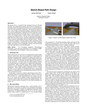
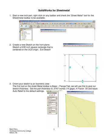
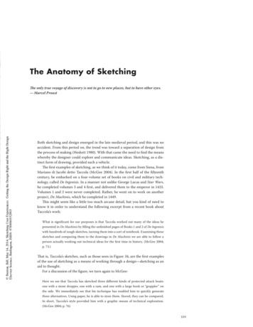
List of Figures1.1A curve composed of clothoids . . . . . . . . . . . . . . . . . . . . . . . .21.2The clothoid . . . . . . . . . . . . . . . . . . . . . . . . . . . . . . . . . .31.3A road network created with Drive . . . . . . . . . . . . . . . . . . . . .42.1Stroke fairing . . . . . . . . . . . . . . . . . . . . . . . . . . . . . . . . .82.2Clothoid fitting . . . . . . . . . . . . . . . . . . . . . . . . . . . . . . . .102.3Sketching in Drive . . . . . . . . . . . . . . . . . . . . . . . . . . . . . .112.4Family of clothoid segments . . . . . . . . . . . . . . . . . . . . . . . . .132.5The effect of Ecost . . . . . . . . . . . . . . . . . . . . . . . . . . . . . . .162.6Rigid 2D transformation . . . . . . . . . . . . . . . . . . . . . . . . . . .182.7End-point weighting . . . . . . . . . . . . . . . . . . . . . . . . . . . . .192.8G1 discontinuities . . . . . . . . . . . . . . . . . . . . . . . . . . . . . . .202.9A G3 continuous curve . . . . . . . . . . . . . . . . . . . . . . . . . . . .212.10 Oversketching using quintic Hermite spline to join . . . . . . . . . . . . .222.11 A gallery of curves . . . . . . . . . . . . . . . . . . . . . . . . . . . . . .242.12 Oversketching . . . . . . . . . . . . . . . . . . . . . . . . . . . . . . . . .253.1Open and closed curves in the system . . . . . . . . . . . . . . . . . . . .303.2Fitting piecewise clothoid curves to sketched input . . . . . . . . . . . . .313.3Simple 2D path editing operations . . . . . . . . . . . . . . . . . . . . . .333.4Occlusion relationships . . . . . . . . . . . . . . . . . . . . . . . . . . . .34vi
3.5Complex model examples . . . . . . . . . . . . . . . . . . . . . . . . . . .363.6Invoking a break-out view . . . . . . . . . . . . . . . . . . . . . . . . . .373.7Oversketching within a break-out view . . . . . . . . . . . . . . . . . . .373.8The break-out lens, with and without background plane . . . . . . . . . .383.9Using the break-out lens to deform meshes . . . . . . . . . . . . . . . . .393.10 Examples of terrain-sensitive sketching, bridges and tunnels . . . . . . .413.11 Example of terrain-sensitive sketching, foliage addition and removal . . .42vii
Chapter 1Introduction“Two roads diverged in a wood,And I took the one less traveled.”– Robert FrostCurves are ubiquitous in Computer Graphics, as primitives to construct shape ordefine shape features, as strokes for sketch-based interaction and rendering or as pathsfor navigation and animation. Motivated originally by curve and surface design for engineering applications, complex shapes are typically represented in a piecewise manner,by smoothly joining primitive shapes (see Figure 1.1). Traditionally, research on curveprimitives has focused on parametric polynomial representations defined using a set ofgeometric constraints, such as Bezier or NURBS curves [12]. Such curves have a compact,analytically smooth representation and possess many attractive properties for curve andsurface design. Increased computing power, however, has made less efficient curve primitives like the clothoid a feasible alternative for interactive design. Dense piecewise linearrepresentations of continuous curves have also become increasingly popular. Desirablegeometric properties, however, are not intrinsically captured by these polylines but needto be imposed by the curve creation and editing techniques used [15, 44, 7].1
2Chapter 1. Introductionclothoidcircular arclinecurvaturearc-lengthFigure 1.1: A curve composed of clothoids, line and circular-arc segments.An important curve design property is fairness [13, 38, 31], which attempts to capturethe visual aesthetic of a curve. Fairness is closely related to how little and how smoothlya curve bends [31] and for planar curves, described as curvature continuous curves witha small number of segments of almost piecewise linear curvature [13].The family of curves whose curvature varies linearly with arc-length were describedby Euler in 1774 in connection with a coiled spring held taut horizontally with a weightat its extremity. Studied in various contexts in science and engineering, such a curveis also referred to as an Euler spiral, Cornu spiral, linarc, lince or clothoid (see Figure1.2). Clothoids are especially useful in transportation engineering, since they can benavigated at constant speed by linear steering and a constant rate of angular acceleration.Roller-coasters are frequently composed of sequences of clothoid loops. While intrinsicgeometric splines like clothoids were introduced in computer aided design in 1972 [35]and subsequently developed as transition curves for road design [29, 45], they have hadlittle recent exposure in mainstream Computer Graphics. In this paper, we exploit thefairness properties of clothoids to fit 2D strokes for sketch-based applications.Mankind has been constructing paths in nature for millenia. While path layouts arenecessary for transportation design (roads, railway tracks, nature trails), they are alsoimportant as motion paths for animation, navigation and visualization in virtual envi-
Chapter 1. Introduction3Figure 1.2: Clothoid: a curve whose curvature varies linearly with arc-length, also knownas an Euler spiral, Cornu spiral or linarc. The above clothoid has a curvature range[ 1.15, 1.15] and arc-length 100 (or t [ 5.362, 5.362], B 3.72).ronments. Noted landscape architect Lawrence Halprin [17] points out that the design ofsuch paths should emphasize the driving experience. In other words, the spatio-temporalaesthetics of path design are as important as its engineering requirements. Unfortunately, unlike 3D shape design where concept sketching interfaces are now abundant,sketch-based path design is largely unexplored. Shape modeling interfaces like GoogleSketchUp, [20, 39], are not suitable for conceptual path layout, forcing designers to reluctantly work with engineering focused CAD tools such as AutoCAD Civil3D.In this paper we present a coherent sketch-based system, Drive, specifically aimed atconceptual path design. While we use road networks to graphically illustrate the system(see Figure 1.3), our system is easily adapted to paths representing railroads, waterways,nature trails, pipe or power lines, graph networks, networks of surface patches and general3D curve based modeling (see Figure 3.9).Being a system focused on sketch-based interaction techniques, Drive differs greatlyfrom applications conventionally used by landscape architects and civil engineers forpath design. University of Toronto landscape architect John Danahy claims professionaltoolsets require “several minutes” to perform useful operations, whereas similar opera-
Chapter 1. Introduction4Figure 1.3: A road network with signs created in Drive.tions can be performed within Drive in seconds by using simple gestures. The ability toproduce prototypes rapidly that integrate themselves into the environment is a significantadvantage. This advantage becomes especially apparent in the modelling of paths whereexact precision is less of a requirement, e.g. a private driveway to a cottage, or a pathtraversed by labourers in logging and forestry.The decision to create a sketch-based system is further justified by attempting tominimize the cognitive overhead that comes with working within the constraints of aparticular modelling system. John Danahy notes that prevalent software toolsets available which perform path and other modelling tasks often force the user to alter their wayof thinking about a problem. For example, the particular ordering of steps of a giventask is ordained by the system and not the user, and may vary from what is conventionalin the profession, which results in cognitive issues during use.An important goal of Drive is that the task of modelling feel very natural and freeform and attempt to avoid or minimize any cognitive issues. This has motivated ourapproach of both interaction and visualization techniques. Considering interaction, asan example, University of Toronto landscape architect Robert Wright has said that theability to sketch a path and embed it on arbitrary geometry is non-trivial and is itselfa useful feature, that is not found in all commercial applications used in his profession.
Chapter 1. Introduction5Considering visualization, as an example, we have developed the break-out lens, a noveltool that provides an alternate viewpoint with significant contextual information, withthe intention of reducing cognitive overhead.Another significant benefit of Drive is the speed at which the system can be learned.All of the operations that can be performed within the system can be explained in somedetail within minutes. Even better, the interface is such that most if not all of thefunctionality can be learned by the user just by giving the sole instruction: open curvescreate paths and closed curves correspond to a selection-action operation and invoke amenu. For all users who experimented with the system, this very brief instruction wasenough to get them started and discover each of the individual system functions on theirown. In contrast, conventional road design applications have a much steeper learningcurve, often coupled by lengthy and complex technical manuals.Designed and implemented within the context of this system, we draw attention tofour novel components:Clothoids: We interactively fit sketched strokes using a number of line, circular-arcand clothoid curve segments. Clothoids are the family of spirals whose curvature varieslinearly with arc-length. They are widely used in transportation engineering, since theycan be navigated at constant speed by linear steering and a constant rate of angularacceleration [29, 45]. Stroke filtering is important for almost all sketch-based applicationsand we show our curves to have smoothness properties superior to the common practiceof spline fitting [37] or iterative point smoothing [44] (see Figure 2.1).Crossing paths: We handle arbitrarily complex path crossings by sketching occlusion asbreaks in the curve path (see Figure 3.4). We process the sketched strokes to implicitlyjoin these breaks and define inequalities of path height. We then efficiently solve forheight along the path as an optimization that minimizes the height of the path from theterrain, the grade of the path, and the overall variation of height needed to satisfy theocclusion relationships (see Figure 3.5).
Chapter 1. Introduction6Break-out lens: Inspired by break-out views used to indicate orthogonal viewpoints inengineering visualization, we develop an interactive lens that performs a continuous viewwarp to provide an in-context break-out view (see Figure 3.8). An important affordanceof the break-out lens is that sketching within the lens allows multi-view 3D curve editing,without the handicap of mentally resolving the 3D curve from disconnected views.Terrain sensitive sketching: An appealing aspect of our system is our focus on boththe construction of path layouts and the rapid conceptualization and preview of the entiredriving experience. The terrain thus is not just a canvas on which to sketch paths butan evolving environment into which the paths integrate, with automatic construction ofbridges, tunnels, road signs and changes in foliage (see Figure 1.3, 3.10, 3.11).
Chapter 2Sketching Piecewise Clothoid Curves2.1Problem statementPolyline stroke data often needs to be denoised and processed into fair 2D curves forfurther use in many sketch-based applications. This is usually done using smoothingfilters [44] or by cubic or high-order spline fitting [36, 37]. Iterative smoothing is bestsuited to removing high-frequency sketching noise and tends to produce low-frequencywiggles in the curve (local pockets of smooth curvature based on filter size). Splinefitting results, though visually smooth, frequently exhibit poor quality curvature plots(see Figure 2.1). We present a new approach to processing sketch strokes using clothoids,that intrinsically favour line and circular arc segments and result in holistically fair G2curves.2.2Overview of our approachOur algorithm for fitting a sequence of G2 clothoid segments to polyline stroke datais a two-step process (see Figure 2.2). We first fit a piecewise linear approximationto the discrete curvature of the stroke as a function of arc-length, with control overthe tradeoff between fitting error and the number of linear pieces. The start and end7
8Chapter 2. Sketching Piecewise Clothoid Curves(a)(b)(c)(d)(e)Figure 2.1: Stroke fairing: (a) A sketched stroke. (b) Clothoid fitting the stroke (a). (c)Cubic spline fitting the clothoid curves in (b). (d) Cubic spline fitting the stroke (a).(e) Laplacian smoothing (4 iterations at 10%) the stroke (a). Curvatures are plotteduncolored along the length of processed strokes (b-d) to evaluate smoothness.
Chapter 2. Sketching Piecewise Clothoid Curves9curvature values of each linear piece uniquely determine a line, circular arc or clothoidcurve segment. These segments further assemble together uniquely with G2 continuityinto a single composite curve. The next step involves determining a single 2D rigidtransform that aligns this composite curve with the sketched stroke to minimize the errorof the stroke from the transformed curve. We are able to solve for this transform efficientlyby formulating the error as a weighted least squares optimization problem. While manysketch-based applications do not require precise interpolation of points and tangents,we show how this can be achieved by inserting or appending short spline segments toenforce interpolation (see Figure 2.10), if necessary. The resulting curve can also bemade G3 by linearly blending the adjacent clothoid segments locally (see Figure 2.9).Alternatively, sharp corners can be allowed by thresholding spikes in curvature to besegment boundaries and independently rotating these segments (see Figure 2.8).2.3ContributionsWe develop a new formulation for efficiently fitting intrinsic spline primitives such asclothoids, to dense polyline data. While we focus on clothoids our algorithmic frameworkis applicable to any curve primitive with a characteristic curvature profile. The resultingcurves are robust to sketching noise and are particularly well suited to sketch-basedapplications. We show a number of enhancements to the basic approach, including sharpcorners, blended G3 curves and point interpolation. Finally, we have implemented ourresults within a sketch-based application for track design (see Figure 2.3), where theclothoid segments provide not only aesthetically pleasing curves but are also requireddownstream, from an engineering standpoint.
10Chapter 2. Sketching Piecewise Clothoid Curves(a)κsketched strokearc-lengthpiecewise linear curvature fitassembled clothoid segments(b)curve alignment: translationcurve alignment: rotationFigure 2.2: Clothoid fitting: (a) Discrete stroke curvature is approximated as a piecewiselinear function uniquely defining clothoid segments. (b) A rigid 2D transform minimizesthe weighted least squares error between the composite clothoid and the sketched stroke.
Chapter 2. Sketching Piecewise Clothoid Curves11Figure 2.3: Sketching clothoid splines within Drive, a sketch-based track modeling system.2.4Related workWe now survey prior work specifically relating to curve and surface fairing in general andon clothoids in particular. A popular feature of cubic splines is that they provide a linearapproximation to the minimum strain energy configuration of a thin-beam interpolatinga set of points. While least squares spline fitting is robust and efficient [37], the curvature plot of the resulting spline can be highly variable (see Figure 2.1). Computing theactual minimum energy curve minimizes the overall bending of the curve [30]. Moretonand Sequin [31] show, however, that minimum variation curves provide a better fairnesscharacteristic by minimizing the overall variation of curvature along the curve allowing natural shapes like circular arcs. These curves are typically computed by nonlinearoptimization techniques. In contrast, we attempt to minimize overall variation in curvature along the curve by robustly approximating it using a number of piecewise linearsegments. Our composite clothoid curve is thus an appealing alternative to minimumvariation curves, particularly when precise interpolation of points is traded for precise
Chapter 2. Sketching Piecewise Clothoid Curves12curvature control.A more common, easy to implement, approach is to iteratively smooth the pointsof piecewise linear curves and surfaces directly [44]. Discrete filtering approaches varyfrom simple neighbour averaging to approaches that use a discrete curvature estimation tohelp guide the fairing process [33]. We similarly compute a discrete curvature estimate atpoints of the input polyline, but instead use these values to determine the segmentation ofthe curve into clothoid pieces. An additional advantage of fitting analytic curve segmentslike splines or clothoids over discrete methods is that the curve can be regenerated atarbitrary resolution.Clothoids have been the subject of prior research in computer aided design. Motivatedby transportation design, Meek and Walton have looked at conditions under which oneor more clothoid segments can form a transition curve between two given curve segments[29]. They have also proposed a clothoid spline [45], where two clothoid pieces are used toform a parabola-like segment between every three consecutive points of a control polygon.While the resulting clothoid spline is G2 , the curve is forced through a point of zerocurvature on every edge of the control polygon. A discrete formulation of clothoid usingnonlinear subdivision has also been proposed [16]. Clothoids have also been used as atransition curve segment for computer vision applications of occluded contour completionand in-painting [26].Originally motivated by a system for quickly sketching track layouts for game environments and road layout conceptualization by landscape architects, we find clothoids tobe attractive curve primitives that qualitatively capture the natural curvature variationsof human sketching well.
Chapter 2. Sketching Piecewise Clothoid Curves2.513Clothoid TerminologyThe clothoid spiral can be parameterized using the Fresnel integralsZtπcos u2 du,2Z0 tπsin u2 du,S(t) 20C(t) (2.1)(2.2)as C(t) πB ,S(t)(2.3)where t is the arc length parameter, and πB is a positive scaling parameter that definesthe slope of linear curvature variation of a family of spirals as seen in Figure 2.4.Figure 2.4: Fixing arc length and an initial curvature parameter, a family of clothoidsegments is formed by decreasing parameter B near infinity (left) toward zero (right).Clothoids can be expressed in a computationally efficient manner, using rational approximations for C(t) and S(t) given in [18]: 112C(t) R(t) sinπ(A(t) t ) ,22 112S(t) R(t) cosπ(A(t) t ) ,22(2.4)(2.5)
Chapter 2. Sketching Piecewise Clothoid Curves14where0.506t 1 ,1.79t2 2.054t 21.A(t) 30.803t 1.886t2 2.524t 2R(t) 2.6Curve fitting using clothoidsWe now detail our approach to curve fitting using a sequence of clothoid, circular arc andline segments (see Figure 1.1,2.11). Note that while the steps below fit a polyline, theycan be used to fit any curve representation that is discretely sampled at an appropriateresolution.2.6.1Discrete curvature estimationDiscrete curvature for planar curves can be estimated at a point using the circum-circleformed with its two adjacent points or the Frenet-Serret fomulae as shown in [33]. Givenany three sequential points pi 1 , pi , pi 1 of the input polyline, using the vectors v1 pi pi 1 , v2 pi 1 pi , the estimated curvature at pi is given by 2 sin 2θ,κ(pi ) p v1 · v2 (2.6)where θ arccosv1v2· v1 v2 .(2.7)Robust statistical approaches to curvature computation that perform better in thepresence of noise and irregular sampling [21] can also be used. The curvature for discretelysampled analytic curves may also directly sampled from the analytic curve.Each point is now mapped into curvature space, where the horizontal axis denotes arclength and the vertical axis, curvature (see Figure 2.2a). We adopt (positive/negative)curvature to denote (right/left) turning in this space.
Chapter 2. Sketching Piecewise Clothoid Curves2.6.215Piecewise linear curvature segmentationWe now segment the curve into a minimal sequence of pieces of linearly varying curvature.A dynamic programming algorithm finds a connected set of line segments which minimizeboth the number of line segments used, and the error in fit with the curvature spacepoints. The number of pieces used is minimized by assigning a penalty Ecost for eachlinear piece. We populate a matrix M with values, in a bottom-up fashion, using thefollowing:M (a, b) min {M (a, k) M (k, b), Ef it (a, b) Ecost } .a k b(2.8)M (a, b) denotes the minimal cost of a configuration of connected line segments from pointa to b. M (a, b) entries are calculated for all a b, making M strictly upper triangular.Ef it (a, b) denotes the vertical error resulting from linear regression with the points froma to b. Expressing the linear regression line using slope and y-intercept, denoting themlslope and lyint respectively, we can define Ef it precisely asEf it (a, b) bX lyint lslope · arclength(pi ) κ(pi ) ,(2.9)i awhere (arclength(pi ), κ(pi )) is the curvature-space point corresponding to pi .The solution, a set of connected line segments in curvature space, defines the set ofconnected clothoid segments that will be used to fit the input curve. Figure 2.5 showsthe effect that different values of Ecost has on the generated solution.2.6.3Segment parameterizationPFor each clothoid segment, we have its curvature space endpoints (xPi , yiP ) and (xPi 1 , yi 1).PyiP and yi 1specify the start and end curvatures of the segment, and the differencexPi 1 xPi specifies the arc length. These parameters uniquely map to a clothoid segmentdefined by the scaling parameter B, and the start and end parameter values t1 and t2 .Since the curvature of a clothoid ist:BPt1 yiP B and t2 yi 1B.(2.10)
Chapter 2. Sketching Piecewise Clothoid lengthFigure 2.5: The effect of Ecost on the generated segmentation. As Ecost decreases, moresegments are used.
17Chapter 2. Sketching Piecewise Clothoid CurvesB can be expressed using the formula for arc length:xPi 1 xPi πB(t2 t1 )PB yiP B) (using (2.10)) πB(yi 1P yiP ) B 2 π(yi 1xPi 1 xPi B2Pπ(yi 1 yiP )and since B must be positive,sB xPi 1 xPi.P yiP )π(yi 1(2.11)Each clothoid segment is translated and rotated to connect end points and aligntangents to adjacent segments resulting in an overall G2 curve (see Figure 2.2a).2.6.42D rigid transformationWe now need to translate and rotate this overall curve, so as to minimize the fittingerror to the input curve. We cast this as a weighted least squares minimization problemas follows: Sample a corresponding set of n points from the canonical clothoid spline,using the arc length positions from the input polyline. Define the set of corresponding S) . Figure 2.6 showsn canonical points with an S superscript: (xS0 , y0S ), . . . , (xSn 1 , yn 1the clothoid spline in its canonical form, with the corresponding set of n points sampledalong it.The goal is to minimize the sum of 2-norm distances between corresponding pairs ofpoints with a rotation matrix R and translation vectors T and T S :n 1Xi 0 R xSi xi S T T yiyiS.(2.12)2Our approach is based on the solution for shape matching shown in [32]. The optimal
Chapter 2. Sketching Piecewise Clothoid Curves18 SFigure 2.6: The points (xS0 , y0S ), . . . , (xSn 1 , yn 1) on the composite curve in pink mustundergo a rigid 2D transformation to match the sketched input curve in white (left). Theresult of the transformation (right).translation vector is given by aligning the weighted centroids of both sets of points: Pn 1S1 i 0 wi xi (2.13)T S Pn 1 P ,n 1Si 0 wii 0 wi yi Pn 11 i 0 wi xi T Pn 1 P(2.14) ,n 1i 0 wiwyi ii 0where each weight wi specifies the relative importance of the corresponding pair of points(xi , yi ), (xSi , yiS ) in the fit (see Figure 2.2b,2.7).Define sets of points which are the relative locations to the centroids qi (xSi , yiS ) T Sand pi (xi , yi ) T . To determine the rotation matrix, the problem is relaxed to findingPn 1the optimal linear transformation A, where we want to minimize i 0wi (Aqi
sketch-based path design is largely unexplored. Shape modeling interfaces like Google SketchUp, [20, 39], are not suitable for conceptual path layout, forcing designers to re-luctantly work with engineering focused CAD tools such as AutoCAD Civil3D. In this paper we present a coherent sketch-based system, Drive, specifically aimed at