Transcription
Hardware Simulator TutorialThis program is part of the software suitethat accompanies the bookThe Elements of Computing Systemsby Noam Nisan and Shimon SchockenMIT Presswww.nand2tetris.orgThis software was developed by students at theEfi Arazi School of Computer Science at IDCChief Software Architect: Yaron UkrainitzHW Simulator Tutorial www.nand2tetris.orgTutorial IndexSlide 1/49
The book’s software suite(All the supplied tools are dual-platform: Xxx.bat startsXxx in Windows, and Xxx.sh starts it in Unix)Simulators(HardwareSimulator, CPUEmulator, VMEmulator): Used to build hardware platforms andexecute programs;This tutorial isabout thehardwaresimulator. Supplied by us.Translators (Assembler, JackCompiler): Used to translate from high-level to low-level; Developed by the students, using the book’sspecs; Executable solutions supplied by us.Other Bin: simulators and translators software; builtIn: executable versions of all the logicgates and chips mentioned in the book; OS: executable version of the Jack OS; TextComparer: a text comparison utility.HW Simulator Tutorial www.nand2tetris.orgTutorial IndexSlide 2/49
The Hack computerThe hardware simulator described in thistutorial can be used to build and test manydifferent hardware platforms. In this book, wefocus on one particular computer, called Hack.Hack -- a 16-bit computer equipped with ascreen and a keyboard -- resembles hand-heldcomputers like game machines, PDA’s, andcellular telephones.The first 5 chapters of the book specify theelementary gates, combinational chips,sequential chips, and hardware architecture ofthe Hack computer.All these modules can be built and tested usingthe hardware simulator described in thistutorial.That is how hardware engineers build chipsfor real: first, the hardware is designed,tested, and optimized on a softwaresimulator. Only then, the resultinggate logic is committed to silicon.HW Simulator Tutorial www.nand2tetris.orgTutorial IndexSlide 3/49
Hardware Simulation TutorialI. Getting startedII. Test scriptsIII. Built-in chipsIV. Clocked chipsV. GUI-empowered chipsVI. Debugging toolsVII. The Hack PlatformRelevant reading (from “The Elements of Computing Systems”): Chapter 1: Boolean Logic Appendix A: Hardware Description Language Appendix B: Test Scripting LanguageHW Simulator Tutorial www.nand2tetris.orgTutorial IndexSlide 4/49
Hardware Simulation TutorialPart I:Getting StartedHW Simulator Tutorial www.nand2tetris.orgTutorial IndexSlide 5/49
Chip Definition (.hdl file)chipinterface/** Exclusive-or gate. out a xor b */CHIP Xor {IN a, b;OUT out;// Implementation missing.} Chip interface: Name of the chipNames of its input and output pinsDocumentation of the intended chip operationTypically supplied by the chip architect; similar to an API, or a contract.HW Simulator Tutorial www.nand2tetris.orgTutorial IndexSlide 6/49
Chip Definition (.hdl file)chipinterface/** Exclusive-or gate. out a xor b */CHIP Xor {IN a, b;OUT out;PARTS:Not(in a, out nota);Not(in b, out notb);And(a a, b notb, out w1);And(a nota, b b, out w2);Or(a w1, b w2, out out);chipimplementation} Any given chip can be implemented in several different ways. This particularimplementation is based on: Xor(a,b) Or(And(a,Not(b)), And(b,Not(a))) Not, And, Or: Internal parts (previously built chips), invoked by the HDLprogrammer nota, notb, w1, w2: internal pins, created and named by the HDL programmer;used to connect internal parts.HW Simulator Tutorial www.nand2tetris.orgTutorial IndexSlide 7/49
Loading a ChipNavigate to adirectory and selectan .hdl file.HW Simulator Tutorial www.nand2tetris.orgTutorial IndexSlide 8/49
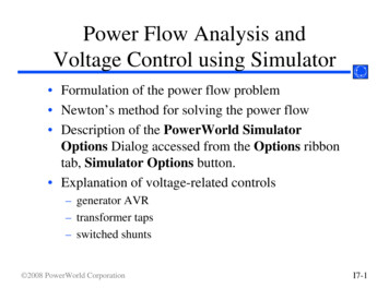
Loading a Chip Names and currentvalues of the chip’soutput pins; Calculated by thesimulator; read-only. Names and current values ofthe chip’s input pins; To change their values, enterthe new values here. Names and current values ofthe chip’s internal pins(used to connect the chip’sparts, forming the chip’s logic); Calculated by the simulator;read-only. Read-only view of the loaded .hdl file; Defines the chip logic; To edit it, use an external text editor.HW Simulator Tutorial www.nand2tetris.orgTutorial IndexSlide 9/49
Exploring the Chip Logic1. Click thePARTSkeywordHW Simulator Tutorial www.nand2tetris.org2. A table pops up, showing the chip’s internalparts (lower-level chips) and whether they are: Primitive (“given”) or composite (user-defined) Clocked (sequential) or unclocked (combinational)Tutorial IndexSlide 10/49
Exploring the Chip Logic1. Click any one ofthe chip PARTS2. A table pops up, showing theinput/output pins of the selectedpart (actually, its API), and theircurrent values;A convenient debugging tool.HW Simulator Tutorial www.nand2tetris.orgTutorial IndexSlide 11/49
Interactive Chip Testing1. User: changes the values of someinput pins2. Simulator: responds by: Darkening the output and internalpins, to indicate that the displayedvalues are no longer valid Enabling the eval(calculator-shaped) button.HW Simulator Tutorial www.nand2tetris.orgTutorial IndexSlide 12/49
Interactive Chip Testing1. User: changes the values of someinput pins2. Simulator: responds by: Darkening the output and internalpins, to indicate that the displayedvalues are no longer validRecalc Enabling the eval(calculator-shaped) button.3. User: Clicked the eval button4. Simulator: re-calculates the valuesof the chip’s internal and outputpins (i.e. applies the chip logic tothe new input values)5. To continue interactive testing,enter new values into the inputpins and click the eval button.HW Simulator Tutorial www.nand2tetris.orgTutorial IndexSlide 13/49
Hardware Simulation TutorialPart II:Test ScriptsHW Simulator Tutorial www.nand2tetris.orgTutorial IndexSlide 14/49
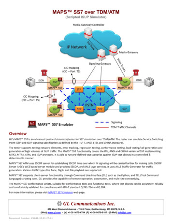
Test Scriptsload Xor.hdl,output-file Xor.out,compare-to Xor.cmp,output-list a%B3.1.3b%B3.1.3out%B3.1.3;set a 0,set b 0,eval,output;set a 0,set b 1,eval,output;Etc. a0011 Test scripts: Are used for specifying, automating andInitreplicatingchip testing Are supplied for every chip mentioned inthe book (so you don’t have to write them) Can effect, batch-style, any operation thatSimulation stepcan be done interactively Are written in a simple language describedGeneratedoutput file(Xor.out)in Appendix B of the bookSimulation Cancreatestepan output file that records theresults of the chip testb0101 out0110HW Simulator Tutorial www.nand2tetris.org If the script specifies a compare file, thesimulator will compare the .out file tothe .cmp file, line by line.Tutorial IndexSlide 15/49
Loading a ScriptTo load a new script (.tstfile), click this button;Interactive loading of the chipitself (.hdl file) may not benecessary, since the testscript typically contains a“load chip” command.HW Simulator Tutorial www.nand2tetris.orgTutorial IndexSlide 16/49
Script ControlsControlsthe scriptexecutionspeedScript series ofsimulationsteps, eachending witha semicolon.Resetsthe scriptPauses thescript executionMulti-step execution,until a pauseExecutes the nextsimulation stepHW Simulator Tutorial www.nand2tetris.orgTutorial IndexSlide 17/49
Running a ScriptScriptexecutionflowTypical “init” code:1. Loads a chip definition (.hdl) file2. Initializes an output (.out) file3. Specifies a compare (.cmp) file4. Declares an output line format.HW Simulator Tutorial www.nand2tetris.orgTutorial IndexSlide 18/49
Running a ScriptComparison of the output lines tothe lines of the .cmp file arereported.ScriptexecutionendsHW Simulator Tutorial www.nand2tetris.orgTutorial IndexSlide 19/49
Viewing Output and Compare FilesHW Simulator Tutorial www.nand2tetris.orgTutorial IndexSlide 20/49
Viewing Output and Compare FilesObservation:This output filelooks like a Xortruth tableConclusion: the chip logic(Xor.hdl) is apparentlycorrect (but not necessarilyefficient).HW Simulator Tutorial www.nand2tetris.orgTutorial IndexSlide 21/49
Hardware Simulation TutorialPart III:Built-in ChipsHW Simulator Tutorial www.nand2tetris.orgTutorial IndexSlide 22/49
Built-In ChipsGeneral A built-in chip has an HDL interface and a Javaimplementation (e.g. here: Mux16.class) The name of the Java class is specified followingthe BUILTIN keyword Built-In implementations of all the chips thatappear in he book are supplied in thetools/buitIn directory.// Mux16 gate (example)CHIP Mux16 {IN a[16],b[16],sel;OUT out[16];BUILTIN Mux16;}Built-in chips are used to: Implement primitive gates (in the computer built in this book: Nand and DFF)Implement chips that have peripheral side effects (like I/O devices)Implement chips that feature a GUI (for debugging)Provide the functionality of chips that the user did not implement for some reasonImprove simulation speed and save memory (when used as parts in complex chips)Facilitate behavioral simulation of a chip before actually building it in HDLBuilt-in chips can be used either explicitly, or implicitly.HW Simulator Tutorial www.nand2tetris.orgTutorial IndexSlide 23/49
Explicit Use of Built-in ChipsThe chip is loaded from thetools/buitIn directory (includesexecutable versions of all the chipsmentioned in the book).Standard interface.Built-in implementation.HW Simulator Tutorial www.nand2tetris.orgTutorial IndexSlide 24/49
Implicit Use of Built-in Chips/** Exclusive-or gate. out a xor b */CHIP Xor {IN a, b;OUT out;PARTS:Not(in a,out Nota);Not(in b,out Notb);And(a a,b Notb,out aNotb);And(a Nota,b b,out bNota);Or(a aNotb,b bNota,out out);} When any HDL file is loaded, the simulator parses its definition. For each internalchip Xxx(.) mentioned in the PARTS section, the simulator looks for an Xxx.hdlfile in the same directory (e.g. Not.hdl, And.hdl, and Or.hdl in this example). If Xxx.hdl is found in the current directory (e.g. if it was also written by the user), thesimulator uses its HDL logic in the evaluation of the overall chip. If Xxx.hdl is not found in the current directory, the simulator attempts to invoke thefile tools/builtIn/Xxx.hdl instead. And since tools/builtIn includes executable versions of all the chips mentioned inthe book, it is possible to build and test any of these chips before first building theirlower-level parts.HW Simulator Tutorial www.nand2tetris.orgTutorial IndexSlide 25/49
Hardware Simulation TutorialPart IV:Clocked Chips(Sequential Logic)HW Simulator Tutorial www.nand2tetris.orgTutorial IndexSlide 26/49
Clocked (Sequential) Chips The implementation of clocked chips is based on sequential logic The operation of clocked chips is regulated by a master clock signal: In our jargon, a clock cycle tick-phase (low), followed by a tock-phase (high) During a tick-tock, the internal states of all the clocked chips are allowed to change,but their outputs are “latched” At the beginning of the next tick, the outputs of all the clocked chips in thearchitecture commit to the new values In a real computer, the clock is implemented by an oscillator; in simulators, clockcycles can be simulated either manually by the user, or repeatedly by a test script.HW Simulator Tutorial www.nand2tetris.orgTutorial IndexSlide 27/49
The D-Flip-Flop (DFF) Gate/** Data Flip-flop:* out(t) in(t-1)* where t is the time unit.*/CHIP DFF {IN in;OUT out;Clocked chips Clocked chips include registers,RAM devices, counters, andthe CPU The simulator knows that theloaded chip is clocked whenone or more of its pins isdeclared “clocked”, or one ormore of its parts (or sub-parts,recursively) is a clocked chip In the hardware platform built inthe book, all the clocked chipsare based, directly or indirectly,on (many instances of) built-inDFF gates.BUILTIN DFF;CLOCKED in, out;}DFF: A primitive memory gate that can“remember” a state over clock cycles Can serve as the basic building block ofall the clocked chips in a computer.HW Simulator Tutorial www.nand2tetris.orgTutorial IndexSlide 28/49
Simulating Clocked ChipsClocked (sequential) chips are clock-regulated.Therefore, the standard way to test a clocked chipis to set its input pins to some values (as withcombinational chips), simulate the progression ofthe clock, and watch how the chip logic respondsto the ticks and the tocks.For example, consider the simulation of an 8-wordrandom-access memory chip (RAM8).Since this built-in chip alsohappens to be GUI- empowered,the simulator displays its GUI(More about GUI-empoweredchips, soon)A built-in,clockedchip(RAM8) isloadedHW Simulator Tutorial www.nand2tetris.orgTutorial IndexSlide 29/49
Simulating Clocked Chips1. User: enterssome inputvalues andclicks theclock icononce (tick)A built-in,clockedchip(RAM8) isloadedHW Simulator Tutorial www.nand2tetris.orgTutorial IndexSlide 30/49
Simulating Clocked Chips1. User: enterssome inputvalues andclicks theclock icononce (tick)2. Simulator:changes theinternal state ofthe chip, but notethat the chip’soutput pin is notyet effected.A built-in,clockedchip(RAM8) isloadedHW Simulator Tutorial www.nand2tetris.orgTutorial IndexSlide 31/49
Simulating Clocked Chips3. User: clicksthe clock iconagain (tock)1. User: enterssome inputvalues andclicks theclock icononce (tick)2. Simulator:changes theinternal state ofthe chip, but notethat the chip’soutput pin is notyet effected.A built-in,clockedchip(RAM8) isloadedHW Simulator Tutorial www.nand2tetris.orgTutorial IndexSlide 32/49
Simulating Clocked Chips3. User: clicksthe clock iconagain (tock)1. User: enterssome inputvalues andclicks theclock icononce (tick)A built-in,clockedchip(RAM8) isloadedHW Simulator Tutorial www.nand2tetris.org4. Simulator:commits thechip’s output pinto the value ofthe chip’sinternal state.Tutorial Index2. Simulator:changes theinternal state ofthe chip, but notethat the chip’soutput pin is notyet effected.Slide 33/49
Simulating Clocked Chips Using a Test ScriptControls the scriptspeed, and thus thesimulated clock speed,and thus the overallchip execution speedSingle-actiontick-tockDefault
The Elements of Computing Systems by Noam Nisan and Shimon Schocken MIT Press www.nand2tetris.org This software was developed by students at the Efi Arazi School of Computer Science at IDC Chief Software Architect: Yaron Ukrainitz Hardware Simulator Tutorial. HW Simulator Tutorial www.nand2tetris.org Tutorial Index Slide 2/49 The book’s software suite This tutorial is about


![Unreal Engine 4 Tutorial Blueprint Tutorial [1] Basic .](/img/5/ue4-blueprints-tutorial-2018.jpg)