Transcription
REVERSE OSMOSIS SFCP SERIESINSTALLATION AND USER GUIDE
Reverse Osmosis System Installation1Table of ContentsINTRODUCTION . 3MANUAL USER’S GUIDE . 3DISCLAIMER STATEMENT . 3PROPRIETARY RIGHTS STATEMENT . 3INSTALLATION . 4EQUIPMENT SUPPORT . 4GENERAL SAFETY GUIDELINES . 4SAFETY PRECAUTIONS. 5SAFETY EQUIPMENT. 5REQUIRED TOOLS AND PARTS . 5EQUIPMENT INSTALLATION GUIDELINES. 6EQUIPMENT INSTALLATION PROCEDURES . 6ELECTRICAL INSTALLATION . 7START UP INSTRUCTIONS . 8PROCEDURE . 8VALVE POSITIONS AND EQUIPMENT STAGE . 8VALVE POSITIONS EFFECT ( Increase; Decrease) . 8PIPING AND INSTRUMENTATION (No Clean in Place) . 9MICRO850 SERIES PLC . 15PANELVIEW 800 TERMINAL – 4.3in TOUCHSCREEN . 16SYSTEM OPERATION . 17GENERAL OPERATION . 17PANELVIEW 800 SCREEN NAVIGATION & COMMANDS . 17SCREEN 1 – HOME . 17SCREEN 2 – TROUBLESHOOTING . 18SCREEN 3 – TDS MONITOR . 19SCREEN 4 - INFO . 19SCREEN 5 -SWITCH SELECTIONS. 20SCREEN 6 – FLOW METER SETPOINTS. 21SCREEN 7 – SENSOR SETTINGS . 21SCREEN 8 - SETPOINTS . 22TANK FULL OPERATION . 23TANK FULL OVERRIDE . 23AUTO RESET . 23ALARM RESET . 23BARRIE ONTARIO CANADA705.733.8900WWW.EXCALIBURWATER.COM
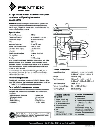
Reverse Osmosis System Installation2SFCP UNIT MODELS/VIEWS OF CRITICAL COMPONENTS . 24SERVICE INSTRUCTIONS . 30REGULAR MAINTENANCE. 30MEMBRANE DIAGRAM. 30MEMBRANE REPLACEMENT. 31SEDIMENT FILTER CARTRIDGE REPLACEMENT . 31SHUTDOWN PROCEDURE . 31SHORT-TERM SHUTDOWN (MAINTENANCE OR SERVICE) . 31LONG-TERM SHUTDOWN (21 DAYS - 1 YEAR) . 31TROUBLESHOOTING . 32MICRO850 CONTROLLER. 32STATUS INDICATORS . 32ERROR CODES. 33SOLENOID VALVE TROUBLESHOOTING . 34HIGH PRESSURE / BOOSTER PUMP . 35PUMP TROUBLESHOOTING . 36MULTI-STAGE VERTICAL PUMP . 40PUMP TROUBLESHOOTING . 41SEDIMENT FILTER HOUSING . 42PERFORMANCE AND SERVICE LOG . 44WARRANTY. 45BARRIE ONTARIO CANADA705.733.8900WWW.EXCALIBURWATER.COM
Reverse Osmosis System Installation3INTRODUCTIONMANUAL USER’S GUIDEThis manual describes the procedures necessary to install, operate, and maintain your Excalibur Water SystemsReverse Osmosis system. Please read this manual carefully before installing and operating your equipment.The equipment warranty may be voided if installation or operation instructions are not followed correctly.This manual has been formatted for ease of use, combining the instruction for the entire RO unit into onemanual. Literature supplied with some major components being used on this equipment is provided in the backof this manual.DISCLAIMER STATEMENTThe operation and maintenance manual are intended to be used with the information provided in the componentmanufacturer’s literature. These manuals should provide complete and accurate information to meet youroperating and/or service requirements based on the information available at the time of publication. However,Excalibur Water Systems assumes no responsibility for the technical content of the component manufacturer’sliterature.The information in these manuals may not cover all operating details or variations or provide for all conditionsin connection with installation, operation and maintenance. Should questions arise which are not answeredspecifically in this manual, contact the Excalibur Water Systems Service Department.Excalibur Water Systems reserves the right to make engineering revisions that may not be reflected in thesemanuals. The material in these manuals is for informational purposes and is subject to change without notice.PROPRIETARY RIGHTS STATEMENTThis manual discloses information in which Excalibur Water Systems has proprietary rights. Neither receiptnor possession of this manual confers or transfers any right to the client, and by its retention hereof, the clientacknowledges that it will not reproduce or cause to be reproduced, in whole or in part, any such informationexcept by written permission from Excalibur Water Systems. The client shall have the right to use and discloseto its employees the information contained herein for the purpose of operating and maintaining the ExcaliburWater Systems equipment, and for no other purpose.In the event the content of this manual is altered or section/items are omitted during a reproduction, in whole orin part, and instructions or definitions within the reproduction result in personal injury to those who follow thealtered instructions, the burden of responsibility for personal injury falls solely on the party who affects thereproduction.BARRIE ONTARIO CANADA705.733.8900WWW.EXCALIBURWATER.COM
Reverse Osmosis System Installation4INSTALLATIONEQUIPMENT SUPPORTExcalibur Water Systems continually strives to provide safe, efficient, trouble-free equipment using theoptimum technology for your application. If problems should develop, our technical support line will beavailable to provide assistance. For service, sales, parts, or additional manual copies call your arearepresentative or the number provided on the bottom of the manual pages.GENERAL SAFETY GUIDELINESThis equipment operates at high voltage and high pressure, has moving parts and hazardous chemicals thatmay cause serious injury or fatality if not operated and maintained according to the procedures outlined inthis manual.1. No one should use or service this equipment without proper training and supervision. It is the responsibilityof the owner to ensure that this equipment is used properly and safely, strictly following the instructionscontained herein.2. Always remain alert during the operation of this equipment. Do not get near this equipment if you aredrowsy or impaired in any way.3. Always wear safety equipment (safety glasses, gloves) for protection while working on the equipment.4. Refer to Material Safety Data Sheets prior to handling hazardous chemicals.5. Always operate the equipment at the parameters specified.6. Never connect the system to piping that has not been approved by Excalibur Water Systems. If there are anydoubts, please call your Excalibur Water Systems local branch.7. Never remove any components from the unit while under pressure.8. No one under the age of 18 years of age should operate or be allowed near this equipment.9. Warning labels have been placed on the equipment to remind the operator of certain hazards. Never removethese labels. If any warning label is illegible or missing, please contact Excalibur Water Systems for a freereplacement.10. Proper maintenance assures the equipment will run properly and can lower the risk of injury. Be sure tofollow the instructions on maintenance carefully.11. Be sure to maintain all equipment, tools and sub-systems used with the equipment.12. Continuously inspect the system for leaks and damage. Correcting problems as they occur will help prolongthe life of the system.13. Use Lock-Out and Tag-Out devices when servicing the unit.BARRIE ONTARIO CANADA705.733.8900WWW.EXCALIBURWATER.COM
Reverse Osmosis System Installation514. This manual should be used as a guidance tool and should not replace common sense. If you are unsureabout a procedure, ask your supervisor. Excalibur Water Systems welcomes any questions you may haveand can arrange to provide on-site training if necessary.SAFETY PRECAUTIONSThe purpose of this manual is to provide the user with the necessary information to operate this equipmentwithout undue risk. Failure to follow the instructions laid forth in this manual may put the operators at risk ofinjury and possible fatality. Please read this entire manual before beginning any procedure; it should alwaysremain with the equipment to act as a ready reference guide for anyone who operates this system.SAFETY EQUIPMENTBelow is a list of equipment and materials that should be kept nearby the equipment.1. Lock-out and Tag-out devices for servicing and shutdowns.2. Eyewash/safety shower for any chemical accidents.3. Safety glasses are always to be worn.4. Earplugs should be worn when encountering high levels of noise.5. Gloves that offer protection from the chemicals used herein.6. Steel toe work boots for protection against heavy equipment and components.REQUIRED TOOLS AND PARTSThe tools and parts specified in this section are the minimum required to install the RO unit at the site. The useof other tools and parts may be necessary, depending on the location chosen and other parameters.Required ToolsLock-Out/Tag-Out equipmentSafety glasses, gloves, earplugsMoving equipmentHammer drill with masonry bitPipe cutting, bending, gluing equipmentRequired MaterialConcrete anchor bolts (size determined by local seismic calculations).Plumbing and electrical materials as requiredBARRIE ONTARIO CANADA705.733.8900WWW.EXCALIBURWATER.COM
Reverse Osmosis System Installation6EQUIPMENT INSTALLATION GUIDELINES1. All lifting and moving procedures must be performed by experienced construction workers usingstandard rigging methods.2. Before beginning any equipment handling procedures, refer to the appropriate sections in theOccupational Health and Safety Act: “General Industry Standards.” Also, refer to any otherapplicable literature and information for cranes, lift trucks, and other equipment used for lifting andmoving.3. Make sure all equipment used for lifting and moving is properly maintained and is in good repair.4. Be sure that components being lifted are balanced and will not tip or slip out of the lifting device.EQUIPMENT INSTALLATION PROCEDURES1. Locate a level, flat, clean, hard surface, capable of supporting the weight of the RO unit. Refer to theEquipment Specification Drawing to determine the floor loading requirements and the service accessspace requirements for the unit.NOTE: This area should have a local floor drain to carry away water which will fall to the floor duringoperation, testing, and servicing of this equipment.2. Lay out the area that the RO System will occupy.3. Move the RO unit to the location laid down in the previous step.4. Drill holes in the pad through the frame tie down holes.5. Level the RO unit by installing shim stock under the frame near the frame tie down holes.6. Install the anchor bolts and secure the frame to the anchor bolts using flat washers, lock washers, andnuts.Do not use the RO unit to support external piping. All plumbing runs should be supported permanufacturers’ recommendations and local codes.7. Install the feed water plumbing line. The plumbing runs should never be smaller than the actual RO inletpipe size and may need to be larger for pipe runs over 50 feet.NOTE:The plumbing materials should be of non-corroding materials (PVC, SST, Copper etc.) Use ofthis material will reduce the tendency to foul the membranes from metal precipitation.8. Install the reject line directly to an open drain.BARRIE ONTARIO CANADA705.733.8900WWW.EXCALIBURWATER.COM
Reverse Osmosis System Installation7NOTE: As a rule, no valves should be installed in this line. If necessary, install a relief valve set at no greaterthan 5 PSIG. The valve should be directed to a visible drain, so relief is clear.If the reject drain is below the level of the RO unit, install a vacuum breaker valve or open pipeleg on the reject line. This will prevent siphoning of all water out of the RO unit duringshutdown.The plumbing installation should now be complete. Check the plumbing to ensure all joints are properlyconnected and supported.ELECTRICAL INSTALLATIONThe following steps consist of electrical work to be performed by a qualified electrician only.1.Employ a Lock Out Device and Lock Out Tag on the RO unit main power supply disconnect switch.2.Run electrical conduit for the high voltage power supply between the Control Panel and the main powersupply.3.Connect any required wiring between the System Controller and the product water storage tank levelsensing device, if required.4.Verify that all electrical connections are secure and wired per the electrical schematic.5.Remove the Lock-Out / Tag-Out equipment from the main power supply for the RO unit, and energizethe circuit.Verify that the voltage supplied is correct and matches the Voltage Identification Tag located on the pumpmotorBARRIE ONTARIO CANADA705.733.8900WWW.EXCALIBURWATER.COM
Reverse Osmosis System Installation8START UP INSTRUCTIONSPROCEDUREThe plumbing must be inspected properly before releasing the water pressure into the system. Direct the productwater flow to drain for first hour of operation. Slowly open the supply valve halfway located upstream of the RO.Connect electrical power to the system. Press the start button and record the pump pressure gauge (Shut off thesystem immediately if pump pressure rises more than 150psi), the pump should start after a delay. The TDSconductivity will be displayed on controller which should decrease gradually. When concentrate flow andpermeate flow stabilizes this means the air has been flushed out of the system. Tune up the concentrate valve andrecirculation valve according to the flow rates given on the performance data sheet or WAVE projection. Checkthe pump pressure gauge and membrane pressure gauge. The pressure difference should always be less than 30psi. After the normal run time of 1 hour, permeate (product) flow can diverted to storage tank. The RO pumpshould shut off and there should be no permeate flow. After 24 hours of operation the TDS, Permeate Flow,Concentrate Flow, Recirculation Flow, Pump Pressure and Membrane Pressure must be recorded and confirmedagain.VALVE POSITIONS AND EQUIPMENT STAGEValveConcentrate Valve (Flow Meter)Recirculation Valve (Flow Meter)DrainWater SupplyStorage TankPre-Treatment EquipmentPositionFully Open¼ OpenFully OpenFully Open (Slowly)Ready for useReady for useVALVE POSITIONS EFFECT ( Increase; embranePressureClosed Open Closed Open BARRIE ONTARIO CANADA705.733.8900WWW.EXCALIBURWATER.COM
Reverse Osmosis System Installation9PIPING AND INSTRUMENTATIONSFC4BARRIE ONTARIO CANADA705.733.8900WWW.EXCALIBURWATER.COM
Reverse Osmosis System Installation10SFC5BARRIE ONTARIO CANADA705.733.8900WWW.EXCALIBURWATER.COM
Reverse Osmosis System Installation11SFC6BARRIE ONTARIO CANADA705.733.8900WWW.EXCALIBURWATER.COM
Reverse Osmosis System Installation12SFC8BARRIE ONTARIO CANADA705.733.8900WWW.EXCALIBURWATER.COM
Reverse Osmosis System Installation13SFC14BARRIE ONTARIO CANADA705.733.8900WWW.EXCALIBURWATER.COM
Reverse Osmosis System Installation14SFC18BARRIE ONTARIO CANADA705.733.8900WWW.EXCALIBURWATER.COM
Reverse Osmosis System Installation15MICRO850 SERIES PLCThe Micro850 PLC controls the outputs of pressure pump, inlet solenoid valve and flush valve. It also controlsthe input signal from inlet pressure switch, tank full switch, pre-treat lockout switch and TDS conductivity cell.The controller functions, switches and TDS calibration can be controlled by navigating to the appropriate screenon the PanelView 800 HMI (Human Machine Interface).Note: The Micro850 PLC is secured within the panel enclosure and should not be tampered with.BARRIE ONTARIO CANADA705.733.8900WWW.EXCALIBURWATER.COM
Reverse Osmosis System Installation16PANELVIEW 800 TERMINAL – 4.3in TOUCHSCREENITEMDESCRIPTION1POWER STATUS LED2TOUCH DISPLAY & FUNCTION KEYS324V DC POWER INPUT4USB DEVICE PORT5MICRO-SD CARD SLOT6MOUNTING SLOTS710/100 MBIT ETHERNET PORT8RS-232 PORT9RS-422 & RS-485 PORT10USB HOST PORT11DIAGNOSTIC STATUS INDICATOR12REPLACEABLE REAL-TIME CLOCKBATTERYBARRIE ONTARIO CANADA705.733.8900WWW.EXCALIBURWATER.COM
Reverse Osmosis System Installation17SYSTEM OPERATIONGENERAL OPERATIONThe SFCP Series Reverse Osmosis system uses a Micro850 PLC and PanelView800 T4T HMI in tandem toprovide operational capability. The Micro850 PLC within the enclosure is not to be handled by the operatorunless directed otherwise. When its power LED indicator is green it is in normal operational status and redwhen it is in screensaver/power-saving mode. The PanelView 800 T4T HMI allows the operator a degree ofcontrol over the SFCP system through its various screens.PANELVIEW 800 SCREEN NAVIGATION & COMMANDSSCREEN 1 – HOMECommandRO System StartRO System StopNext ScreenPrevious ScreenActionPress & hold "System Start" until "System Status" becomes "Active"Press & hold "System Stop" until "System Status" becomes "Inactive"Press F4 key or "Next" on the screenPress F1 key or "Prev" on the screenThe default startup screen upon booting of the PLC and the PanelView 800 is the home screen. Here primaryinformation is displayed. Note that not all the information displayed in Figure 1 will appear as is. Icons such asthe ones for the Booster Pump, Inlet Valve, and Bypass Valve will change color when those components areverified as operational. The System Status panel will show either Active or Inactive dependent on the state ofthe RO system, tank level indicators will also vary, and the “FLUSH ACTIVE” alert is active only during thefirst 5 minutes of startup.BARRIE ONTARIO CANADA705.733.8900WWW.EXCALIBURWATER.COM
Reverse Osmosis System Installation18SCREEN 2 – TROUBLESHOOTINGThe “Troubleshooting” screen will allow the operator to bypass sections of the RO system during maintenanceor diagnostics. The operator may also manually control outputs from the screen as well as reset fault alarms.The “FAULT” button will not appear unless there is a fault condition. Note: The “Login” and “Logout”options can only be accessed by contacting Excalibur Water Systems and receiving the proper information.CommandLow Pressure Switch BypassHigh Pressure Switch BypasspH BypassPermeate (Product) BypassFeed TDS BypassBooster Pump ControlInlet Valve ControlSoft Water Fill ControlFault ResetHome ScreenNext ScreenPrevious ScreenActionPress and hold "LPS BYPASS" for desired length of time.Press and hold "HPS BYPASS" for desired length of time.Press and hold "PH BYPASS" for desired length of time.Press and hold "PRM TDS BYPASS" for desired length of time.Press and hold "FEED TDS BYPASS" for desired length of time.Press "BOOSTER PUMP" to toggle it on or off.Press "INLET VALVE" to open or close the valve.Press "SOFT WATER FILL" to open or close the valve.Press "FAULT." The text will change to "FAULT RESET" to indicate success.Press F3 key or "Home" on the screen.Press F4 key or "Next" on the screen.Press F1 key or "Prev" on the screen.BARRIE ONTARIO CANADA705.733.8900WWW.EXCALIBURWATER.COM
Reverse Osmosis System Installation19SCREEN 3 – TDS MONITORThe “TDS MONITOR” screen allows the operator to view the TDS of both the feed water and permeate in realtime.CommandHome ScreenNext ScreenPrevious ScreenActionPress F3 key or "Home" on the screen.Press F4 key or "Next" on the screen.Press F1 key or "Prev" on the screen.SCREEN 4 - INFOThe “INFO” screen allows for the viewing of other variables during operation of the RO system. No commandscan be made on this screen aside from moving between other screens or returning to the home screen.BARRIE ONTARIO CANADA705.733.8900WWW.EXCALIBURWATER.COM
Reverse Osmosis System Installation20SCREEN 5 -SWITCH SELECTIONS“SWITCH SELECTIONS” allows the operator to toggle switches within the program between Normally Open(N/O) or Normally Closed (N/C). Auto reset may also be enabled or disabled here (Auto Reset is enabled bydefault from the factory). The permeate valve may also be open or closed manually from here.CommandLOW NOHIGH NOAUTO RESETSOFT FILLTANK LOWTANK MIDTANK HIGHHome ScreenNext ScreenPrevious ScreenActionPress "LOW NO" to toggle between N/O and N/C.Press "HIGH NO" to toggle between N/O and N/C.Press "AUTO RESET" to disable or enable auto reset after a fault occurs.Press "SOFT FILL" to either open or close the permeate valve manually.Press "TANK LOW" to toggle the switch between N/O and N/C in the program.Press "TANK MID" to toggle the switch between N/O and N/C in the program.Press "TANK HIGH" to toggle the switch between N/O and N/C in the program.Press F3 key or "Home" on the screen.Press F4 key or "Next" on the screen.Press F1 key or "Prev" on the screen.BARRIE ONTARIO CANADA705.733.8900WWW.EXCALIBURWATER.COM
Reverse Osmosis System Installation21SCREEN 6 – FLOW METER SETPOINTSFlow meter setpoints can be changed on “FLOW METER SETPOINTS.” Note that settings on this screen may not bechanged without approval from the manufacturer. Please contact directly for any requests.CommandPERMEATE FLOW METERCONCENTRATE FLOW METERRECIRCULATION FLOW METERHome ScreenNext ScreenPrevious ScreenActionPress "MIN FLOW" and enter setpoint on numeric keypad. Repeat with "MAX FLOW."Press "MIN FLOW" and enter setpoint on numeric keypad. Repeat with "MAX FLOW."Press "MIN FLOW" and enter setpoint on numeric keypad. Repeat with "MAX FLOW."Press F3 key or "Home" on the screen.Press F4 key or "Next" on the screen.Press F1 key or "Prev" on the screen.SCREEN 7 – SENSOR SETTINGSBARRIE ONTARIO CANADA705.733.8900WWW.EXCALIBURWATER.COM
Reverse Osmosis System Installation22Read ranges on the TDS and pH level sensors can be adjusted from the “SENSOR SETTINGS” screen. Notethat settings on this screen may not be changed without approval from the manufacturer. Please contact directly forany requests.CommandTDS LEVEL RANGEADJUSTpH LEVEL RANGE ADJUSTHome ScreenNext ScreenPrevious ScreenActionPress "MIN RANGE" and enter read range on numeric keypad. Repeat with "MAXRANGE."Press "MIN RANGE" and enter read range on numeric keypad. Repeat with "MAXRANGE."Press F3 key or "Home" on the screen.Press F4 key or "Next" on the screen.Press F1 key or "Prev" on the screen.SCREEN 8 - SETPOINTSSetpoints regarding limits on feed/permeate limits and delays can be adjusted on this screen. Note that settingson this screen may not be changed without approval from the manufacturer. Please contact directly for any requests.CommandFEED TDS UPPER LIMITPERMEATE TDS UPPERLIMITSOLENOID VALVE DELAYLOW PRESSURE DELAYHIGH PRESSURE DELAYTANK LOW DELAYTANK FULL DELAYHome ScreenPrevious ScreenActionPress "FEED TDS" button to the right of text, enter limit setpoint on numeric keypadPress "PERMEATE TDS" button to the right of text, enter limit setpoint on numerickeypadPress "VALVE DELAY" button to the right of text, enter limit setpoint on n
Reverse Osmosis System Installation 5 . 14. This manual should be used as a guidance tool and should not replace common sense. If you are unsure about a procedure, ask your supervisor. Excalibur Water Systems . welcomes any questions you may have and can arrange to provide on-site training if necessary. SAFETY PRECAUTIONS