Transcription
TRB255Copyright 2020, Teltonika Networks. Specifications and information given in this document are subject to change by Teltonika Networks without prior notice.
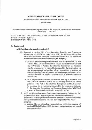
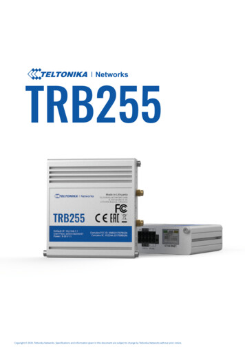
DATASHEET // TRB255HARDWAREFRONT VIEWInput/outputconnectorEthernet portPower LEDBACK VIEWMobile signal strengthindication LEDsMobile network typeLEDsResetbuttonGPS antennaconnectorMobile antennaconnectorINPUT/OUTPUT 16 PIN CONNECTOR PINOUTD1, D2, D3 - Configurable digital Input/Output pins.Open collector output, max output 30 V, 300 mA orDigital input where 0-6 V detected as logic low and8-30 V – logic high. - 9-30 VDC positive power pinCTS - RS232 clear data to send pin (output).RTS - RS232 request data to send pin (input).R - RS485 receiver positive signal pin.D - RS485 driver positive signal pin.- - Negative/ground power pin.- Ground pins for D1, D2, D3, A, RS232 and RS485.A - Analog input pin. Analog voltage range 0-30 V.TX - RS232 transmitted data (input).RX - RS232 received data (output).R- - RS485 receiver negative signal.D- - RS485 driver negative signal.Copyright 2020, Teltonika Networks. Specifications and information given in this document are subject to change by Teltonika Networks without prior notice.2
DATASHEET // TRB255FEATURESMOBILEMobile moduleLTE (Cat M1) / NB-IoT / EGPRSSIM switch2 SIM cards, auto-switch cases: weak signal, data limit, SMS limit, on roaming, no network, network denied, data connection failStatusSignal strength, Connected band, SINR, RSRP, RSRQ, Bytes sent/receivedBridgeDirect connection (bridge) between mobile ISP and device on LANSMSSMS status, SMS configuration, send/read SMS via HTTP POST/GET, EMAIL to SMS (planned), SMS to EMAIL (planned), SMS toHTTP (planned), SMS to SMS (planned), scheduled SMS (planned), SMS autoreply (planned)Black/White list (planned)Operator black/white listMultiple PDN (planned)Possibility to use different PDNs for multiple network access and servicesBand managementUsed band status display, Band lock (planned)APNAuto APNETHERNETLAN1 x LAN port 10/100 Mbps, comply IEEE 802.3, IEEE 802.3u standards, supports auto MDI/MDIXNETWORKRoutingStatic routing, Dynamic routing (BGP, OSPF v2, RIP v1/v2) (planned)Network protocolsTCP, UDP, IPv4, IPv6, ICMP, NTP, DNS, HTTP, HTTPS, FTP, SMTP, SSL v3, TLS, ARP, PPP (planned), UPNP (planned), SSH, DHCP,Telnet, MQTT, Wake On Lan (WOL) (planned)VoIP passthrough support(planned)H.323 and SIP-alg protocol NAT helpers, allowing proper routing of VoIP packetsConnection monitoringPing Reboot, Periodic Reboot, LCP and ICMP for link inspectionFirewallPort forward, traffic rules, custom rulesDHCPStatic and dynamic IP allocation, DHCP RelayQoS / Smart QueueManagement (SQM) (planned)Traffic priority queuing by source/destination, service, protocol or port, WMM, 802.11eDDNS (planned)Supported 25 service providers, others can be configured manuallySSHFS (planned)Possibility to mount remote file system via SSH protocolSECURITYAuthenticationPre-shared key, digital certificates, X.509 certificatesFirewallPre-configured firewall rules can be enabled via WebUI, unlimited firewall configuration via CLI; DMZ; NAT; NAT-TAttack prevention (planned)DDOS prevention (SYN flood protection, SSH attack prevention, HTTP/HTTPS attack prevention), port scan prevention (SYN-FIN,SYN-RST, X-mas, NULL flags, FIN scan attacks)VLAN (planned)Tag based VLAN separationMobile quota controlCustom data limits for both SIM cardsWEB filter (planned)Blacklist for blocking out unwanted websites, Whitelist for specifying allowed sites onlyAccess controlFlexible access control of TCP, UDP, ICMP packets, MAC address filterVPNOpenVPNMultiple clients and server can be running simultaneously, 12 encryption methodsOpenVPN EncryptionDES-CBC, RC2-CBC, DES-EDE-CBC, DES-EDE3-CBC, DESX-CBC, BF-CBC, RC2-40-CBC, CAST5-CBC, RC2-64-CBC, AES-128-CBC,AES-192-CBC, AES-256-CBCIPSecIKEv1, IKEv2, with 5 encryption methods (DES, 3DES, AES128, AES192, AES256)PPTP, L2TPClient/Server services can run simultaneouslyDMVPN (planned)Method of building scalable IPsec VPNsGRE (planned)GRE tunnelCopyright 2020, Teltonika Networks. Specifications and information given in this document are subject to change by Teltonika Networks without prior notice.3
DATASHEET // TRB255SERIAL COMMMUNICATION MODESModesConsole, OverIP, Modem (planned), Modbus RTU master, Modbus gateway, NTRIP client (planned)MODBUS TCP SLAVEID filteringRespond to one ID in range [1;255] or anyAllow remote accessAllow access through WANCustom registersModbus TCP custom register block, which allows to read/write to a file inside the router, and can be used to extend ModbusTCP slave functionalityMODBUS TCP MASTERSupported functions01, 02, 03, 04, 05, 06, 15, 16Supported data formats8 bit: INT, UINT; 16 bit: INT, UINT (MSB or LSB first); 32 bit: float, INT, UINT (ABCD (big-endian), DCBA (little-endian), CDAB,BADC)MODBUS RTU MASTERSupported baud ratesFrom 300 to 3000000Supported functions01, 02, 03, 04, 05, 06, 15, 16Supported data formats8 bit: INT, UINT; 16 bit: INT, UINT (MSB or LSB first); 32 bit: float, INT, UINT (ABCD (big-endian), DCBA (little-endian), CDAB,BADC)Number of data bits7 or 8Number of stop bits1 or 2Parity bitsNone, Even, OddFlow controlNone, RTS/CTS (only for RS232 interface), Xon/XoffMQTT GATEWAYGatewayAllows sending commands and receiving data from Modbus Master trough MQTT brokerMODBUS DATA TO SERVERSupported functionsHTTP(S), MQTT, Azure MQTT (planned)MONITORING & MANAGEMENTWEB UIHTTP/HTTPS, status, configuration, FW update, CLI, troubleshoot, event log, system log, kernel logFOTAFirmware update from server, automatic notificationSSHSSH (v1, v2)SMSSMS status, SMS configuration, send/read SMS via HTTP POST/GETCall (planned)Reboot, Status, Mobile data on/off, Output on/off, answer/hang-up with a timerTR-069 (planned)OpenACS, EasyCwmp, ACSLite, tGem, LibreACS, GenieACS, FreeACS, LibCWMP, Friendly tech, AVSystemMQTT (planned)MQTT Broker, MQTT publisherSNMP (planned)SNMP (v1, v2, v3), SNMP TrapJSON-RPCManagement API over HTTP/HTTPSModbusModbus TCP status/controlRMSTeltonika Remote Management Systems (RMS)POWERConnector2 pins in 16 pin industrial terminal blockInput voltage range9 – 30 VDC, reverse polarity protection, surge protection /-1 kV 50 µs maxPower consumptionIdle: 1.2 W, Max: 5 WCopyright 2020, Teltonika Networks. Specifications and information given in this document are subject to change by Teltonika Networks without prior notice.4
DATASHEET // TRB255SYSTEM CHARACTERISTICSCPUQualcomm QCA9531, MIPS 24kc, 650 MHzRAM64 MB, DDR2Flash memory16MB SPI Flash (4 MB available for user)FIRMWARE / CONFIGURATIONWEB UIUpdate FW from file, check FW on server, configuration profiles, configuration backupFOTAUpdate FW/configuration from serverRMSUpdate FW/configuration for multiple devicesKeep settingsUpdate FW without losing current configurationFIRMWARE CUSTOMIZATIONOperating systemRutOS (OpenWrt based Linux OS)Supported languagesBusybox shell, Lua, C, C Development toolsSDK package with build environment providedLOCATION TRACKINGGNSSGPS, GLONASS, BeiDou, Galileo and QZSSCoordinates (planned)GNSS coordinates via WebUI, SMS, TAVL, RMSNMEANMEA 0183NTRIP (planned)NTRIP protocol (Networked Transport of RTCM via Internet Protocol)Server software (planned)Supported server software TAVL, RMSMobile Network GeolocatingLocation without using GPS, get approximate location based on mobile tower on RMSGeofencing (planned)Configurable multiple geofence zonesINPUT/OUTPUTConfigurable I/O3 x Configurable Inputs/Outputs. Digital input 0 - 6 V detected as logic low, 8 - 30 V detected as logic high. Open collectoroutput, max output 30 V, 300 mAAnalog input1 x Analog input (0 - 30 V)Events (planned)SMS, EmailOutput controlHTTP POST/GET, ScheduleI/O juggler (planned)Allows to set certain I/O conditions to initiate eventSERIALRS232Terminal block connector: TX, RX, RTS, CTSRS485Terminal block connector: D , D-, R , R- (2 or 4 wire interface)Supported baud ratesFrom 300 to 3000000Number of data bits7 or 8Number of stop bits1 or 2ParityNone, Even, OddFlow controlNone, RTS/CTS (only for RS232 interface), Xon/XoffIoT PLATFORMSCloud of Things (planned)Allows monitoring of: Device data, Mobile data, Network info, AvailabilityThingWorx (planned)Allows monitoring of: WAN Type, WAN IP Mobile Operator Name, Mobile Signal Strength, Mobile Network TypeCumulocity (planned)Allows monitoring of: Device Model, Revision and Serial Number, Mobile Cell ID, ICCID, IMEI, Connection Type, Operator, SignalStrength, WAN Type and IPAzure IoT Hub (planned)Can send device IP, Number of bytes send/received/ 3G connection state, Network link state, IMEI, ICCID, Model, Manufacturer,Serial, Revision, IMSI, Sim State, PIN state, GSM signal, WCDMA RSCP, WCDMA EC/IO, LTE RSRP, LTE SINR, LTE RSRQ, CELL ID,Operator, Operator number, Connection type, Temperature, PIN count to Azure IoT Hub serverCopyright 2020, Teltonika Networks. Specifications and information given in this document are subject to change by Teltonika Networks without prior notice.5
DATASHEET // TRB255PHYSICAL INTERFACES (PORTS, LEDS, ANTENNAS, BUTTON, SIM)Ethernet1 x RJ45 port, 10/100 MbpsI/O’s3 x Configurable I/O, 1 x Analog input in 16 pin terminal blockStatus LEDs3 x connection status LEDs, 3 x connection strength LEDs, 1 x power LED, 1 x Eth port status LEDSIM2 x SIM slots (Mini SIM – 2FF), 1.8 V/3 V, double stacked SIM trayPower2 pins in 16 pin terminal blockAntennas1 x SMA connector for Mobile, 1 x SMA connector for GNSSRS2324 pins in 16 pin terminal block (TX, RX, RTS, CTS)RS4854 pins in 16 pin terminal block (D , D-, R , R-)ResetReboot, restore to user default (planned), restore to factory defaultsPHYSICAL SPECIFICATIONCasing materialAluminium housing with DIN rail mounting optionDimensions74 x 83 x 25 mm (L x W x H)Weight165 gMounting optionsDIN rail, wall mounting (additional kits needed), flat surface placementOPERATING ENVIRONMENTOperating temperature-40 C to 75 COperating humidity10% to 90% non-condensingCopyright 2020, Teltonika Networks. Specifications and information given in this document are subject to change by Teltonika Networks without prior notice.6
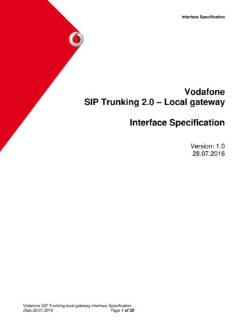
DATASHEET // TRB255HARDWARE INSTALLATION1. Unscrew two back panel hex bolts and remove the back panel.2. Insert your SIM card(s) into the SIM socket(s), which are locatedon the bottom side of PCB.3. Attach the panel and tighten the hex bolts.4. Attach the mobile antenna (max torque 0.4 N·m / 3.5 lbf·in).5. Connect open PSU leads to 16 pin terminal block:a) red wire to top row first contact ( );b) black wire to bottom row first contact (-).6. Connect the 16 pin terminal block to gateway 16 pin connectorand plug other end of the power adapter into a power outlet.SIM1SIM2LOGIN TO DEVICE1. Power on the device and connect the Ethernet cable to your computer.2. Allow the gateway to boot up. This might take up t3. To enter the gateway Web interface (WebUI), type http://192.168.1.1 into the URL field of your Internet browser.4. Use login information shown in image A when prompted for authentication.5. After you log in, you will be prompted to change your password for security reasons. The new password must contain at least 8 characters,including at least one uppercase letter, one lowercase letter and one digit. This step is mandatory, and you will not be able to interact withthe gateway WebUI until you change the password.6. When you change the gateway password, the Configuration Wizard will start. The Configuration Wizard is a tool used to set up some ofthe gateway main operating parameters.7. Go to the Overview page and pay attention to the Signal Strength indication (image B). To maximize the cellular performance try adjustingthe antennas or changing the location of your device to achieve the best signal conditions.A.B.-65 dBmadminData connection stateadmin01StateConnectedRegistered (home); OPERATOR; 4G (LTE)SIM card slot in useBytes received/sent*Ready348.7 KB / 223.5 KBTECHNICAL INFORMATIONRadio specificationsRF technologiesEGPRS, NB-IoT, LTE (Cat-M1), GNSSMax RF power33 dBm@GSM, 23 dBm@LTEBundled accessories specifications*Power adapterInput: 0.4 A@100-240 VAC, output: 9 VDC, 1 A, connected to 16 pin terminal blockMobile antenna698 960 / 1710 2690 MHz, 50 Ω, VSWR 3, gain** 3 dBi, omnidirectional, SMA male connectorGNSS antenna1575.42 1602 MHz, 2.2 5 VDC, VSWR 1.5, gain** 28 dB (typ.), RHCP polarization, SMA male connector*Order code dependent.**Higher gain antenna can be connected to compensate for cable attenuation when a cable is used. The user is responsible for the compliance with the legal regulations.Copyright 2020, Teltonika Networks. Specifications and information given in this document are subject to change by Teltonika Networks without prior notice.7
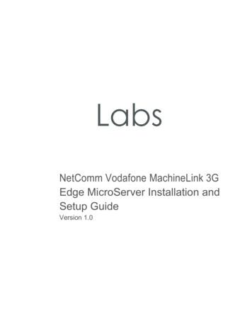
DATASHEET // TRB255WHAT'S IN THE BOX?STANDARD PACKAGE CONTAINS Gateway TRB255 Euro PSU 1 x Mobile antenna (swivel, SMA male) 1x GNSS antenna (adhesive, SMA male, 3 m cable) 16 pin terminal block 1 x hex key Ethernet cable (1.5 m) QSG (Quick Start Guide) Packaging boxTRB2551 X LTE ANTENNA (SWIVEL, SMAMALE)1X GNSS ANTENNA (ADHESIVE, SMAMALE, 3 M CABLE)EURO PSU1 X HEX KEYETHERNET CABLE (1.5 M)16 PIN TERMINAL BLOCKCopyright 2020, Teltonika Networks. Specifications and information given in this document are subject to change by Teltonika Networks without prior notice.8
DATASHEET // TRB255STANDARD ORDER CODESPRODUCT CODEHS CODEHTS CODEPACKAGE CONTAINSTRB2550000008517628517.62.00Standard PackageFor more information on all available packaging options – please contact us directly.AVAILABLE VERSIONSPRODUCT CODEREGION (OPERATOR)FREQUENCYTRB2550*****Global4G (LTE-FDD): B1, B2, B3, B4, B5, B8, B12, B13, B18, B19, B20, B284G (LTE-TDD): B39 (for Cat M1 only)2G: B2, B3, B5, B8The price and lead-times for region (operator) specific versions may vary. For more information please contact us.Copyright 2020, Teltonika Networks. Specifications and information given in this document are subject to change by Teltonika Networks without prior notice.9
DATASHEET // TRB255MOUNTING OPTIONSDIN RAIL KITParameterValueMounting standard35mm DIN RailMaterialLow carbon steelWeight57gScrews includedPhilips Pan Head screw #6-32 3/16, 2pcsDimensions82 mm x 46 mm x 20 mmRoHS CompliantVDIN RAIL KITDIN Rail adapterPhilips Pan Head screw #6-32 3/16, 2pcs for RUT2xx/RUT9xxORDER CODEPRODUCT CODEHS CODEHTS CODE088-00267PR5MEC00732690987326.90.98For more information on all available packaging options – please contact us directly.COMPACT DIN RAIL KITParameterValueMounting standard35mm DIN RailMaterialABS PC plasticWeight6.5 gScrews includedPhilips Pan Head screw #6-32 3/16, 2pcsDimensions70 mm x 25 mm x 14,5 mmRoHS CompliantVDIN RAIL KITCompact plastic DIN Rail adapter (70x25x14,5mm)Philips Pan Head screw #6-32 3/16, 2pcsORDER CODEPRODUCT CODEHS CODEHTS CODE088-00270PR5MEC11732690987326.90.98For more information on all available packaging options – please contact us directly.SURFACE MOUNTING KITParameterValueMounting standardFlat surface mountMaterialABS PC plasticWeight2x5 gScrews includedPhilips Pan Head screw #6-32 3/16, 2pcsDimensions25 mm x 48 mm x 7.5 mmRoHS CompliantVDIN RAIL KITSurface mounting kitPhilips Pan Head screw #6-32 3/16, 2pcsORDER CODEPRODUCT CODEHS CODEHTS CODE088-00281PR5MEC12732690987326.90.98For more information on all available packaging options – please contact us directly.Copyright 2020, Teltonika Networks. Specifications and information given in this document are subject to change by Teltonika Networks without prior notice.10
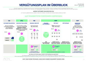
DATASHEET // TRB255TRB255 SPATIAL MEASUREMENTS & WEIGHTMAIN MEASUREMENTSH x W x D dimensions for TRB255:Device housing*:74 x 83 x 25Box:173 x 148 x 71*Housing measurements are presented without antenna connectors and screws; for measurements of other device elements look to the sections below.TOP VIEWThe figure below depicts the measurements of TRB255 and its components as seen from the top:RIGHT VIEWThe figure below depicts the measurements of TRB255 and its components as seen from the right side:Copyright 2020, Teltonika Networks. Specifications and information given in this document are subject to change by Teltonika Networks without prior notice.11
DATASHEET // TRB255FRONT VIEWThe figure below depicts the measurements of TRB255 and its components as seen from the front panel side:REAR VIEWThe figure below depicts the measurements of TRB255 and its components as seen from the back panel side:Copyright 2020, Teltonika Networks. Specifications and information given in this document are subject to change by Teltonika Networks without prior notice.12
DATASHEET // TRB255MOUNTING SPACE REQUIREMENTSThe figure below depicts an approximation of the device's dimensions when cables and antennas are attached:Copyright 2020, Teltonika Networks. Specifications and information given in this document are subject to change by Teltonika Networks without prior notice.13
DATASHEET // TRB255DIN RAILThe scheme below depicts protrusion measurements of an attached DIN Rail:Copyright 2020, Teltonika Networks. Specifications and information given in this document are subject to change by Teltonika Networks without prior notice.14
Server software (planned) Mobile Network Geolocating INPUT/OUTPUT 3 x Configurable Inputs/Outputs. Digital input 0 - 6 V detected as logic low, 8 - 30 V detected as logic high. Open collector output, max output 30 V, 300 mA Configurable I/O 1 x Analog input (0 - 30 V) SMS, Email Analog input Events (planned) Output control HTTP POST/GET, Schedule