Transcription
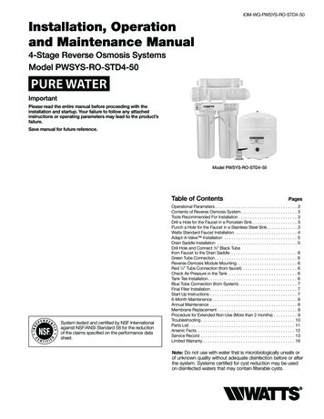
4-Stage Reverse Osmosis Water Filtration SystemInstallation and Operating InstructionsModel RO-2550IMPORTANT: Before installing this reverse osmosis system, makecertain your water supply complies with the following operatingspecifications. Failure to do so may reduce the effectiveness of thesystem and will void the warranty.SpecificationsThin Film Membrane:TFM-50Feed Water Pressure:40 to 100 psi (2.75–6.9 bar)Temperature Range:40–100 F (4.4–37.7 C)TDS:2000 ppmMaximum Hardness†:10 gpg (171 mg/L)Sulfide, Iron and Manganese‡:0 ppm 0.1 ppmChlorine in Water Supply:Less than 2 ppmpH Limits:3–11Daily Product Water Rate:15.04 gpd (56.93 Lpd)TDS Rejection:96.2%Turbidity:11 NTU AverageIf the hardness of your water is above 10 gpg (171 mg/L), lime scalewill build up rapidly on the membrane. Scale buildup will plug themembrane and make the system ineffective. We do not recommendthese reverse osmosis systems to be used with water in excess of10 gpg (171 mg/L) hardness.†A maximum total level of approximately 0.01 ppm sulfide, iron ormanganese is permissible. See your local dealer to reduce thesesubstances in your water.‡Production CapabilitiesTested by NSF International according to NSF/ANSI Standard 58 hasgiven 15.04 gallons per day. Source water test parameters are 50 psig,77 F, pH of 7.5 0.5 and 750 ppm total dissolved solids.Parts Included: (See back of manual for diagram)Pre-assembled filter system (mounting bracket, membrane housing,membrane, pre- and post-filter housings and pre- and post-filtercartridges). Reverse osmosis membraneInlet supply adapterDrain clamp 1/4-inch TubingTank valve Storage tank Chrome faucet Feed tubing Sump wrenches 3/8-inch TubingSystem Dimensions:Overall Dimensions:131 2-inch W x 51 2-inch D x 171 4-inch H(34.29 cm W x 12.7 cm D x 43.8 cm H)Weight:17.3 lbs. (7.84 kg)Tank Dimensions:131 2-inch W x 9 inch D x 9 inch H(34.29 cm W x 22.86 cm D x 22.86 cm H)Tank Capacity Max:2.8 gal. (10.6 L)Tank Air Pressure Empty:5 to 7 psi (0.34 to 0.48 bar)Tank Weight (Full):28.5 lbs. (12.9 kg)Tools and MaterialsRequired H and or electric drill(cordless preferred) (2) Adjustable wrenches Slotted and Phillipsscrewdrivers File Safety glassesThe RO-2550 is Tested and Certified by NSF International against NSF/ANSI Standard 58 for the reduction of Total Disolved Solids, Fluoride,Turbidity, Lead, Selenium, Copper and Cysts. Drill bits: 1/8", 3/16", 1/4", 3/8"If sink does not have hole forseparate faucet: Center punch Cone-shaped grinding wheel 1-1 4" hole saw or drill bit Safety maskNOTE: All tools may not benecessary for installation. Readinstallation procedures beforestarting to determine what toolsare necessary.Technical Support: 1-800-279-9404 (M-F 7:30 am - 5:00 pm CST) SH247113 Rev A JE10
PrecautionsGENERALHOW REVERSE OSMOSIS WORKSWARNING: Do not use with water that is microbiologicallyunsafe or of unknown quality without adequate disinfection before orafter the system. Systems certified for cyst reduction may be used ondisinfected waters that may contain filterable cysts.CAUTION: Filter must be protected against freezing, which cancause cracking of the filter and water leakage.CAUTION: Because of the product’s limited service life and toprevent costly repairs or possible water damage, westrongly recommend that the bottom of all plastichousings be replaced every five years for clear and tenyears for opaque. If the bottom of your housing has beenin use for longer than this period, it should be replacedimmediately. Date the bottom of any new or replacementhousing to indicate the next recommended replacementdate.The RO-2550 Reverse Osmosis (RO) System uses a semi-permeablemembrane to reduce dissolved salts and minerals, improving thetaste and odor of your water. The RO membrane is made of layers ofmicron-thin film wound around a hollow center core. Water moleculescan pass through the membrane, but dissolved salts and minerals arerejected.The RO-2550 Reverse Osmosis System features 4-stage filter action.Your water supply is pre-filtered to reduce dirt and chlorine that mayfoul the membrane. The RO membrane separates this pre-filteredwater into PRODUCT WATER and DRAIN or REJECT WATER. Incomingwater pressure forces the product water through the membraneand into the storage tank. Dissolved solids and other contaminantscannot pass through the membrane and are sent to the drain as rejectwater. When you open the drinking water faucet, product water isdrawn from the storage tank through an activated carbon post-filter,providing you with cleaner, great-tasting water.For each gallon of water produced, several gallons are dischargedas reject water. The storage tank can hold up to 2.8 gallons (10.6 L)of water at a time, for drinking and cooking needs. When used underthe Specifications on page 1 of the manual, your Reverse Osmosismembranes should last 12-24 months.NOTE: Your water must be within required limits for satisfactory operation.If not, your membrane life may be shortened and your warranty willbe voided (see Specifications on page 1). This reverse osmosis system will not protect against diseasecausing bacteria or remove naturally-occurring harmless bacteria.BASIC INSTALLATION PROCEDURE GUIDELINES Install on cold water line only. For standard, under-sink installation on 3/8-inch (10 mm) steel, brass,or copper cold water line. Please read all instructions and precautions before installing andusing your RO-2550. Numbered diagrams correspond with numbered steps. Do not use wicking or sealer to fit connections into the cap of thefilter. Teflon tape is recommended. Make certain that installation complies with all state and local lawsand regulations. The replacement cartridges and reverse osmosis membraneincluded with this system have limited service lives. Changes intaste, odor, and color of the water being filtered indicate that thecartridge should be replaced (see Replacing the Pre- and PostFilters on page 8, and Replacing the Membrane, on page 9). After prolonged periods of non-use (such as during a vacation) it isrecommended that the system be flushed for 5 minutes before it isused. A drinking water cartridge may contain carbon fines (very fine blackpowder). After installation, flush the system for 5 minutes to removethe carbon fines before using the water. It is recommended that you run the tap at least 20 seconds prior tousing water for drinking or cooking purposes. The contaminants or other substances removed or reduced by thiswater treatment device are not necessarily present in your water.RO MEMBRANE PRECAUTIONSCAUTION: C hlorine will destroy the TFM-50 membrane. If you usethe RO-2550 with a chlorinated or periodically-chlorinatedwater supply, it is ABSOLUTELY NECESSARY to use acarbon pre-filter (included with the system). This carbonpre-filter should be changed at least every 3 months toavoid chlorine bypass. See Warranty for disclaimers andlimitations that apply to the TFM-50 membrane.NOTE: To make sure no chlorine is present in the water that reaches themembrane, you may want to use a chlorine test kit to check thebrine/reject water that flows from the membrane to the drain. Nochlorine should be detected. The TFM-50 membrane is resistant to naturally-occurring bacteria.2
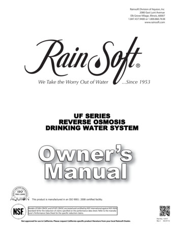
Installation Read all installation and operating instructions before installing and using your RO system.Numbered diagrams correspond with numbered steps.1. Installing the Water Supply AdapterThe supply adapter fits 1/2-inch 14 NPS threads. If local codes permit, it may be used toconnect the RO-2550 to the cold water supply line. If local codes do not permit the useof the supply adapter, alternate connectors can be obtained from your local plumbingwholesaler.1BCDirections:ADD(A) Turn off cold water inlet supply line. If cold water line does not have a shut-off valveunder the sink, you should install one.(B) Turn on the cold water faucet and allow all water to drain from line.(C) Disconnect cold water line from 1/2-inch 14 NPS threaded stub on bottom of mainfaucet.(D) Using the nut that previously connected the cold water line to the faucet, screw thecold water line to the male supply adapter threads.2. Selecting the Faucet LocationThe drinking water faucet should be positioned with function, convenience andappearance in mind. An adequate flat area is required to allow faucet base to rest securely.The faucet fits through a 11 4-inch hole. Most sinks have pre-drilled 11 2-inch or 13 8-inchdiameter holes designed for spray hoses. The drinking water faucet may be installed usingone of these holes, despite their larger size. If these pre-drilled holes cannot be used or arein an inconvenient location, it will be necessary to drill a 11 4-inch hole in the sink or throughcountertop next to the sink for the faucet.CAUTION: This procedure may generate dusts which can cause severe irritation if inhaledor come in contact with the eyes. The use of safety glasses and safety mask forthis procedure is recommended.CAUTION: Do not attempt to drill through an all-porcelain or porcelain-coated sink. Forapplications on these types of sinks we recommend using the sprayer hole ormounting the faucet through the countertop.CAUTION: When drilling through a countertop make sure the area below the drilled areais free of wiring and piping. Make certain that you have ample room to makethe proper connections to the bottom of the faucet.CAUTION: Do not drill through a countertop that is more than 1 inch thick.CAUTION: Do not attempt to drill through a tiled, marble, granite or similar countertop.Consult a plumber or the countertop manufacturer for advice or assistance.The following instructions apply to stainless steel sinks ONLY.(A) Line bottom of sink with newspaper to prevent shavings, parts or tools from fallingdown the drain.(B) Place masking tape over the area to be drilled to help prevent scratches if drill bit slips.(C) Mark point with center punch. Use a 1/4-inch drill bit to drill a pilot hole through sink.(D) Use a 11 4-inch hole saw to enlarge hole. Smooth rough edges with a file.2Pilot HoleBC1/4"1D 4”C11 4"11 4”DMountingHoleA3BC3. Mounting the FaucetD(A) Loosen stem-nut on faucet, remove metal slotted disc (if attached).(B) Attach large diameter 3/8-inch drain tube to barb fitting at the faucet base. This tubeshould be long enough to reach the drain clamp in Step 4.(C) Attach small diameter 1/4-inch drain tube to other barb fitting at faucet base. This tubeshould be long enough to reach right side of the RO Assembly.(D) Slide chrome plate and black rubber washer onto faucet by threading both drain tubesthrough the holes on the plate and washer.(E) Slide white extension onto long threaded section of faucet. Open end of extensionshould come in contact with base of faucet.(F) Apply 3-5 wraps of Teflon tape to faucet stem. Screw quick connector onto end ofthreads.(G) Wet end of 3/8" tube. Push into bottom of connector. Tug gently to be sure connection iscomplete.NOTE: To remove the tube, push on the fittings' collar and pull the tube out.(H) Holding the faucet, feed the three tubes through the hole in the sink. Position thefaucet handle at a desired location.3Counter TopAIEFG
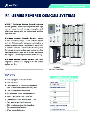
Installation Continued . . .(I) Center the faucet and slip slotted disc between the white extension and the bottom ofthe counter or sink. Tighten the stem nut with a wrench until it is tight.(J) Firmly insert goose-neck spout into faucet base.4A4. Installing the Drain Clamp6"NOTE: If you have a single-basin sink with a disposal unit, call Technical Support foroptions.NOTE: Before installing the drain clamp, check the drainpipes under the sink for corrosion.Corroded pipes should be replaced before continuing with installation.(A) Attach the drain clamp to a vertical section of the drainpipe, about 6 inches abovethe trap. Make sure the opening on the drain clamp is facing towards the drinking waterfaucet (see diagram on previous page).(B) Using the fitting hole of the drain clamp as a guide, drill a 1/4-inch hole through one sideof the drainpipe.(C) Remove the drain clamp from the drainpipe and enlarge the hole with a 3/8-inch drill bit.Use a file to remove rough edges from the drilled hole.(D) Make sure the black rubber gasket is adhered to the inside of the drain clamp andplace the drain clamp assembly over the drilled hole. Look through the hole and positionthe clamp so that the center of the clamp hole is slightly higher (about 1/16-inch) thanthe center of the drilled hole. Tighten the clamp securely.(E) Screw the plastic compression nut onto the drain clamp until hand-tight.BCE5. Connecting the Faucet to the DrainCAUTION: This is a gravity drain line. Any loops, kinks or sharp bends must be eliminatedbefore proceeding. Failure to create a straight line to the drain may result inreject water leaking through the air gap in the faucet onto the countertop andbelow the faucet.(A) Align the larger reject (3/8-inch) tubing from the faucet with the compression nut on thedrain clamp. Create as straight and smooth a path as possible with the tubing. Do notkink tube. Cut the tubing squarely below the nut and remove the internal and externalburrs.D5A3/8" Tube(B) Loosen the compression nut two complete turns. Insert the tubing into the nut untilit stops. Tighten with fingers, then tighten 1 to 2 turns with a wrench.6. Installation of Mounting Screws(A) If system is being installed under the kitchen sink, locate it on back or right wall.Make sure to allow ample space for installation. To change the filter cartridges,a minimum of 11 2-inches of clearance is required underneath the filter housings.A minimum of 2 inches of clearance from the left side of the unit is also required or5 inches from the left bracket mounting screw hole.(B) Install mounting screws at least 15 inches from cabinet floor and 71 2-inches apart.Leave a 5/16-inch space between the head of the screw and the wall to slip bracketonto screws.NOTE: Each connection fitting on the RO Assembly has a plug that must be removedbefore inserting tubing. Push in on the collar and pull the plug out.B67. Connecting the Faucet to the System15"(min.)11 2" (min.)Port Reference7A471 2"2" (min.)(A) Locate the reject tubing (reject water line) from the drinking water faucet. This tube isthe smaller of the two. Place a mark on the tubing 5/8-inch from the end. Moisten theend of the tubing with water and insert tubing into the quick-connect fitting on the flowrestrictor found on the right side of system behind the membrane.If tubing is not firmly connected, leaking will occur. It is important for the tubing to beinserted all the way until the mark is flush with the outer edge of the quick-connect insert.NOTE: Tubing may be quickly and easily removed from the fitting if necessary by pressingthe collar around the fitting then pulling the tubing with your other hand.(B) The faucet tube from the bottom of the threaded metal tube is inserted into the postfilter. The fitting is at the top left of the RO System. Push the free end of the tubing intothe quick connect fitting.5" (min.)B
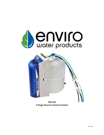
Installation Continued . . .8. Connecting the Storage Tank to the SystemCAUTION: When tank is full, it weighs approximately 28.5 lbs. (12.9 kg) Provide ample81/4" Tubesupport under the tank.(A) To prevent leaks, apply 3 or more wraps of Teflon tape to threads on tank. Thread thetank valve onto the top of the tank opening. Turn tank so handle is in line with tubing.CAUTION: The tank /valve connection will leak if not properly sealed. Teflon tape willnormally seal the threaded connection.(B) Locate the 1/4-inch tubing. Place a mark on the tubing 5/8-inch from each end. Moistenone end of the tubing with water and insert with a twisting motion into the port of thetank valve until the 5/8-inch mark is flush with the quick connect fitting. Then locate thetank near the system's installation area.(C) Cut the tubing to correct length. Install free end of tubing into white quick-connectfitting on the post filter tee on the right side. Do not cut tubing.B5/8"AApplyTeflon tapePort ReferenceC(D) Place entire system over mounting screws on wall and slide down.CAUTION: Make certain system is firmly attached to wall to prevent it from falling andpossibly becoming damaged.NOTE: Use caution not to bend or pinch the tubing behind the system while attaching tomounting screws.9. Connecting the Supply Adapter and Inlet Filter9A5/8"16 mm(A) Locate remaining length of 1/4-inch plastic tubing.(B) Push into quick connect fitting on the right side of system.(C) Cut the tube to a length that will allow connection to the cold water supply fitting.Ensure the tubing does not kink. Push the tube into the fitting.C1/4" Tube10. Installing the Membrane(A) Remove tube attached to membrane housing by pressing in the white collar around thefitting while pulling the tubing with your other hand.(B) Hold the membrane housing with one hand and turn the cap (wrench provided) withother hand to remove. To make it easier to hold the membrane housing, you may wantto remove the post-filter.5/8"16 mmPort Reference(C) With clean hands (sanitary gloves preferred), remove the membrane from the plasticbag. HANDLE WITH CARE.CAUTION: Do not unwrap the tape around the membrane, as it is part of the membrane.Do not squeeze membrane.(D) With the double O-ring side first, push membrane into housing until it stops.About 1/8-inch of the membrane’s plastic core will stick out beyond the housing.(E) Use clean silicone grease (pack is included with the system) to lubricate both O-ringsand the brine seal. Hand-tighten membrane housing cap until you feel resistance, thentighten an additional 1/2 turn. Do not over-tighten.(F) Reinsert the tube by pushing it into the quick connect fitting.BE10DAPort ReferenceA5
Installation Continued . . .1111. Faucet Operation(A) For controlled water flow, push the handle down.(B) For constant water flow, lift the faucet handle to lock it in the open position.12. System Start-upANOTE: The reverse osmosis membrane is treated with a food grade sanitizing agentthat may cause an undesirable taste. Although it is not harmful, it should beflushed from the system.Push DownNOTE: The post-polishing filter may contain fine black carbon particles. These fines areharmless, but may make the water appear gray in color. The carbon fines areflushed from the system with the first tank full of water.NOTE: The RO system does not produce a high volume of water on demand as anordinary filter does. Water is produced at a slow, drop-by-drop rate. The systemrequires about 2 to 4 hours to fill the storage tank. As water is taken from thetank, the system automatically starts the cycle of replacing the water and thenstops water production when the tank is full.CAUTION: Visually check the entire system for leaks. If a leak is present, seeTroubleshooting on page 10.(A) Turn off valve at top of storage tank.(B) Turn on the cold water supply.(C) Lift the faucet handle to lock it in the open position and let it drip for 30 minutes.(D) Completely open the cold water supply until it comes to a stop. Allow water to drip fromthe faucet for 12 more hours. Then close the faucet and open the valve on the storagetank. The tank valve is open when the handle lines up with the tubing connection.(E) Allow 2 to 4 hours for the tank to fill. Again, periodically check the installation for leaks.After the storage tank is filled, open the faucet to flush the post-polishing filter. Allow 4to 5 minutes for all of the water to drain from the tank.(F) Close faucet and allow tank to fill.Push UpB12AClosedTank ValveOpenTank ValveBCounterclockwise(G) Repeat steps E and F four times.NOTE: Initially, the water may appear cloudy. This is a result of air trapped in the postpolishing filter. It is not harmful and will disappear in a matter of minutes. It maytake up to a week after installing a new post-polishing filter for the trapped air todissipate.The system is ready for operation. You can now enjoy quality water from your ReverseOsmosis System.Testing Your Reverse Osmosis SystemModel RO-2550 Reverse Osmosis SystemTotal Dissolved Solids (TDS) TestNOTE: Under NSF/ANSI Standard 58, it is highly recommended that you (the consumer)have your water tested at least every 6 months to verify that your system isperforming satisfactorily.SAMPLING INSTRUCTIONS:Sampling instructions are included with the Total Dissolved Solids (TDS) Test Kit. If the TDSTest Kit is missing from your unit, please call 800.861.8758 for a replacement.Total DissolvedSolids Test Kit6
Optional InstallationConnecting your Reverse Osmosis System to Refrigerator Icemaker / Water DispenserCAUTION: If you are connecting this unit to your refrigerator/icemaker with initial RO installation, wait to turn on the icemaker until the post-polishing filter has been flushed according to Step 12.CAUTION: Use plastic tubing and fittings. Do not use copper tubing or brass fittings.NOTE: F or optimum performance, it is recommended that the distance between the RO system and the refrigerator icemaker/water dispenser be nogreater than 10 feet (3 m). At distances greater than 10 feet, the water pressure from the system may not be adequate to deliver water to therefrigerator.MATERIALS REQUIRED (available from your local hardware store): 3/8-inch x 3/8-inch x 3/8-inch (0.952 cm x 0.952 cm x 0.952 cm) compression or quick-connect tee 10 feet (3 m) of 3/8-inch (0.952 cm) polyethylene tubing Shut-off valve1. Turn off refrigerator water supply and icemaker (consult manufacturer’s guidelines).2. Close tank valve (on top of storage tank).3. Turn off water to RO system at the cold water supply.4. Open drinking water faucet to relieve pressure.5. Locate tubing (permeate) leading to your drinking water faucet. Cut and insert the3/8-inch x 3/8-inch x 3/8-inch compression or quick-connect tee into the permeate tubing.Consult manufacturer’s guidelines before installing the supply adapter.NOTE: When cutting the permeate tubing, you may experience some water leakage.6. Using a length of 3/8-inch polyethylene tubing, connect theicemaker/dispenser line with the free port on the compression tee.7. The shut-off valve should be installed as close to this port of the teeas possible. Shut-off valve should be installed in the OFF positionConsult manufacturer’s guidelines before installing the shut-off valve.8. Completely open cold water supply.9. Open tank valve.10. Turn off the drinking water faucet.11. Turn on water to RO system at cold water supply.12. Turn on icemaker and open shut-off valve.Consult manufacturer’s instructions.13. Check for leaks and tighten connections if necessary.47365271
Replacing the Pre-Filter and Post-Filter Cartridges7. Insert cartridges in the bottom of the housings. Make surecartridge slips over standpipe in the bottom of the housing.1st Stage Pre-Filter and 2nd Stage Pre-Filter Cartridges:The cartridge should be replaced every six months. If yourwater contains a high amount of sediment, it may be necessary tochange the 1st stage cartridge more frequently. If your water containsa high amount of chlorine, it may be necessary to change the 2ndstage pre-filter more often.1. Turn off incoming water supply and valve on the storage tank.Place a tray under the system to catch any water that spills duringremoval of the filter housings.2. O pen faucet to release pressure.3. U nscrew bottom of filter housings from caps. Use the filter wrench.Discard used cartridges.4. Remove black rubber O-rings from grooves in housings. Wipegrooves and O-rings clean; set O-rings aside.5. Rinse out housings and fill each 1/3 with water. Add 2 tablespoons ofbleach and scrub with non-abrasive brush or sponge. Rinse thoroughly.6. L ubricate each O-ring with a coating of clean silicone grease. Withtwo fingers, press each O-ring securely into groove below thethreads of the appropriate housing.NOTE: Be sure to install cartridges in proper housings (see diagram below).8. Screw bottoms of housings back onto caps securely; do notover-tighten. Turn on cold water supply.Check for leaks. Continue to check periodically to make sureno leaks develop.4th Stage Post-Filter Cartridge: post-filter should be replaced everytwelve months.1. Turn off incoming water supply and valve on the storage tank.Place a tray under the system to catch any water that spills duringremoval of the filter housings.2. O pen faucet to release pressure.3. Remove filter from bracket and discard.4. Remove tubes from fittings by pressing in collar around the fittingwhile pulling the tubing out with your other hand.NOTE: If quick connect fittings need to be installed, tape threads offittings with 3 wraps of Teflon tape and attach to filter.CAUTION: Ensure the tape is not touching O-ring on the fitting or aCAUTION: The rubber O-ring providesleak may occur.NOTE: T he filter has an arrow on it showing the direction of flow.The tee fitting connects to the inlet side of the filter and theelbow fitting attaches to the outlet side.NOTE: Hand tighten fittings, then tighten with wrench 1/4 turn.5. Attach 4th stage filter to bracket with the tee fitting on the righthand side.6. Attach tubes to fittings by pushing in until the tube stops. Check tosee if tube is in place by trying to gently pull tube out.the water-tight sealbetween the cap and thebottom of the housing.It is important thatthe O-ring be properlyseated in the groovebelow the threads ofthe housing or a waterleak could occur.1/4" FaucetDrain Tube3/8" Drain TubeGS-10RO(4th Stage Post-Filter)1/4" Feed Tube3/8" FaucetPermeate TubeTFM-50 Membrane(3rd Stage Pre-Filter)P5(1st StagePre-Filter)EPM10(2nd StagePost-Filter)81/4" StorageTank PermeateTube
Replacing the 3rd Stage Reverse Osmosis MembraneAbout the Reverse Osmosis Membrane11. Close the cold water supply and turn on the drinking water faucet.Let the faucet run for about 30 seconds before turning off.When used under operating conditions specified on page 1 of themanual, your reverse osmosis membrane should last at least oneyear. You should replace the membrane after 18 to 24 months. Replaceit sooner if you notice a return of unpleasant tastes or odors or anoticeable decline in water production. The precise life span of yoursystem's membrane will depend on the quality of the water enteringthe system and the frequency with which you use it. Frequent systemuse prevents the filtered salts and minerals from building up onthe membrane as scale. The more water the system is required toproduce, the longer the membrane will last. You may wish to find avariety of uses for your system in order to prolong the life ofthe membrane.12. Let the entire system stand for 30 minutes to sanitize.13. After 30 minutes, turn on the drinking water faucet to allow thebleach water to run out (about 3 to 5 minutes).14. Unscrew bottom of housings. Discard bleach water and rinse.Replacing the Membrane and Filter CartridgesTo replace the filters, see Replacing the Pre-Filters andPost-Filter on page 8.To replace the membrane, see Step 10: Installing the MembraneNOTE: After installing new membrane and cartridges, allow systemto run for 3 hours to fill tank. Check for leaks every hour. Aspressure builds in tank, leaks may occur that did not existdirectly after installation.When the membrane and cartridges have been changed, follow thesystem start-up procedure in Step 12: System Start-up.During extended periods of non-use (such as during a vacation),remove the membrane from the membrane housing and place it ina sealed plastic bag. Store membrane in refrigerator for future use.DO NOT FREEZE.NOTE: If system stands for more than 2 to 3 days without being used,the storage tank should be emptied.Replacing the Membrane and Sanitizing the System andFiltersNOTE: It is recommended that you sanitize the system each timeyou change the membrane. It is not necessary to sanitize thesystem when changing only the pre-filters or post-filter.NOTE: When installing a new membrane, it is recommended thatyou replace the pre-filter and post-filter cartridges as well.Removing the Membrane and Filters1. Turn off the cold water supply. Allow five minutes for system todepressurize.Place a tray under the system to catch any water that spillsduring removal of the filter housings.2. Open drinking water faucet to drain tank. When tank is drained,close faucet.3. Hold the membrane housing with one hand and remove the capwith the other hand.CAUTION: Do not disconnect tubing from membrane cap.4. To remove the RO membrane, grasp membrane tube with pliersand pull. Discard old membrane. Screw cap back onto membranehousing. DO NOT install new membrane.5. Unscrew filter housings from caps and discard used cartridges.6. Remove black rubber O-rings from grooves in housings.Wipe grooves and O-rings clean; set O-rings aside.Sanitizing the System7. Rinse out bottom of housings and fill each 1/3 with water.Add 2 tablespoons of household bleach to each housing and scrubcap, bottom of housings, and membrane housing with non-abrasivesponge or cloth. Rinse thoroughly.8. Lubricate O-rings with a coating of clean silicone grease. Withtwo fingers, press each O-ring securely into groove below thethreads of the appropriate housing.CAUTION: The rubber O-ring provides the water-tight seal betweenthe cap and the bottom of the housing. It is important thatthe O-ring be properly seated in the groove below thethreads of the housing or a water leak could occur.9. Screw bottom of housing onto caps WITHOUT inserting prefiltersand hand-tighten. Do not over-tighten.10. Open the cold water supply and let the system run for 2 to 3 minutesto carry the bleach solution throughout the system.9
Troubleshooting GuideLeaks between bottom of housing and capNo water pressure from the drinking water faucet orlow volume in storage tank1. Ensure sump is tightly screwed to cap. If it still leaks close
these reverse osmosis systems to be used with water in excess of 10 gpg (171 mg/L) hardness. ‡A maximum total level of approximately 0.01 ppm sulfide, iron or manganese is permissible. See your local dealer to reduce these substances in your water. Production Capabilities Tested by NSF International according to NSF/ANSI Standard 58 has