Transcription
Ontario Wood BridgeReference GuideBy Moses Structural Engineers andBrown & Co. Engineering Ltd. for theCanadian Wood Council and the OntarioMinistry of Natural Resources and Forestry
CONtaCtOntario Wood WORKS!1350 Fisher Street, Unit 115North Bay, ON P1B 2H1authorsMoses Structural Engineers: David Moses, Mary Alexander, Katherine McAlister, Karen MesaBrown & Co. Engineering Ltd.: Andrew Lehan, Stephen Brown, and Genaro DulayacknowledgementsThe Canadian Wood Council/Ontario Wood WORKS! wishes to thank the Ontario Ministry ofNatural Resources and Forestry, FedNor, Natural Resources Canada, the Province of Québec,and cecobois. Their financial and in-kind contributions made the publication of this documentpossible.This report was prepared with the technical assistance of Professor Paul Gauvreau, Dr.sc.techn., P.Eng., Professor at the University of Toronto, Department of Civil Engineering.Thank you to the following individuals who provided interviews to the authors:Jasmine Wang, Ph.D., P.Eng. of the Canadian Wood Council, Andrew Lehan, P.Eng., M.A.Sc.of Brown and Company., Marshall Leslie of M.Leslie, Inc., Caroline Frenette, ing. Ph.D. ofcecobois, Richard Krutzler of LEA Consulting Ltd., and James Wacker of the US FPL.Thank you to the following individuals who peer reviewed the document:Jasmine Wang, Ph.D., P.Eng. of the Canadian Wood Council and Caroline Frenette, ing. Ph.D.of cecobois.Thank you to the following individuals who peer reviewed the design examples:Tyler McQuaker, P.Eng., Sr. Structural Engineer from NWR Structural Section/Ministry ofTransportation Ontario, Cory Zurell, PhD, P.Eng., Principal from Blackwell Structural Engineersand François Pelletier, ing, Direction générale des structures from Ministère des Transports, dela Mobilité durable et de l’Électrification des transports.Thank you to the following individuals who supplied reference material for the document:Patrick Crabbe from Atlantic WoodWORKS!, Percy Champagne from FPInnovations, JohnPineau from FPInnovations, Mohammad Mohammad from FPInnovations and NRCan, DanTingley from TRS/WRD, Gary Farnden from Government of BC, Ministry of Transportationand Infrastructure, Terry MacKay from Government of BC, Ministry of Transportation andInfrastructure, Brian Chow from Government of BC, Ministry of Transportation and Infrastructure,Keven Durand from Nordic Structures and Crawford Dewar from Guardian Bridge RapidConstruction.
Copyright 2017Copyright notice:With the permission of Canadian Standards Association, (operating as “CSA Group”), 178Rexdale Blvd., Toronto, ON, M9W 1R3, material is reproduced from CSA Group’s standardS6-14 – Canadian Highway Bridge Design Code. This material is not the complete and officialposition of CSA Group on the referenced subject, which is represented solely by the Standardin its entirety. While use of the material has been authorized, CSA Group is not responsible forthe manner in which the data is presented, nor for any representations and interpretations. Nofurther reproduction is permitted. For more information or to purchase standard(s) from CSAGroup, please visit http://shop.csa.ca/ or call 1-800-463-6727.Disclaimer:It is intended that this guide is to be used in conjunction with competent engineering design.The authors, Moses Structural Engineers Inc., Brown & Co. Engineering Ltd., Ontario WoodWORKS!, the Canadian Wood Council, the Ministry of Natural Resources and Forestry andtheir contractors make no warranty, expressed or implied, or assume any legal liability orresponsibility for the use, application of and/or reference to the information included in thispublication and/or omissions in this work, or for any engineering designs, plans, or constructionprepared from it. Consult your local jurisdiction or design professional to assure compliancewith code, construction, and performance requirements. This guide does not exempt applicantsfrom obtaining any other authorization(s) required by any law or regulation, as the case may be.Photo credit for cover:Stephane GroleauOntario Wood Bridge Reference Guidei
FORWaRDTimber bridges have a long history of construction and use throughout North America, includingOntario, for roadways, railways and logging roads. The Canadian Highway Bridge Design Code(CHBDC), together with the Canadian Wood Council publication Wood Highway Bridges from1992 are typically referenced by designers of timber bridges in Ontario. This new reference isintended to provide updated background information for designers as they embark on proposingand designing timber highway bridges for primary and secondary roads.This reference is divided into three parts:Part 1 – Wood Bridges – Design and UsePart 2 – Opportunities & Current LimitationsPart 3 – Design ExamplesPart 1 provides background information on topics including wood materials, bridge systems,prefabrication, durability and species availability. Details of costs, construction cycle andsustainability are also provided. Part 1 concludes with examples of a variety of completedhighway bridges from North America and Europe.Part 2 of this reference is intended to provide designers and authorities with highlights of thecurrent edition of the CHBDC on subjects related to the wood highway bridges, including areasthat will require future development in the code. Additional references to other resources foradvancing practitioner knowledge of and advancing the state of the art in wood bridge designare provided.Part 3 has two fully worked design examples of a two-lane 18-m span wood highway bridgedesigned in accordance with the latest provisions of the CHBDC and the best availableinformation from current literature. Each example is based on a single-span, simply-supportedglued-laminated girder bridge. One bridge has a glued-laminated deck and the other has astress-laminated deck. These examples are intended to help designers understand the keyissues as they undertake wood highway bridge design. Durability through detailing and choiceof materials is discussed.ii Ontario Wood Bridge Reference Guide
taBLE OF CONtENtSPaRt ONE – WOOD BRiDGESDESiGN aND USEPaRt tWO – OPPORtUNitiES &CURRENt LiMitatiONS1.1.2.1.Introduction .562.2.Review of CAN/CSA S6 – CanadianHighway Bridge Design Code .58Introduction .21.1.1.1.2.1.3.Scope .5Wood Bridge Systems and Technology .51.2.1.Wood Bridge Materials.51.2.2.Wood Bridge Systems .71.2.2.1.Decks .71.2.2.2.Super Structures . 111.2.2.3.Sub-Structures . 171.2.2.4.Other Systems . 17Wood Bridge Design Considerations .172.2.1.CAN/CSA S6 –Section 1 – General .582.2.2.CAN/CSA S6 –Section 2 – Durability .592.2.3.CAN/CSA S6 –Section 3 – Loads .592.2.4.CAN/CSA S6 –Section 4 – Seismic Design .592.2.5.CAN/CSA S6 – Section 5 –Methods of Analysis .602.2.6.CAN/CSA S6 – Section 6 –Foundations andGeotechnical Systems .631.3.1.Canadian Highway BridgeDesign Code (CHBDC) . 181.3.2.MTO Ontario ProvincialStandard Specification . 181.3.3.Ontario HeritageBridge Guidelines. 182.2.7.1.3.4.Prefabrication .19CAN/CSA S6 – Section 7 –Buried Structures .631.3.5.Prestressing .202.2.8.CAN/CSA S6 – Section 8 –Concrete Structures .631.3.6.Service Life and Durability .212.2.9.1.3.7.Species .22CAN/CSA S6 – Section 9 –Wood Structures .631.3.8.International RecentPractices .222.2.9.1Clause 9.4 Limit States Design .642.2.9.2.Clause 9.5 General Design .641.4.Wood Bridge Protection .232.2.9.3.Clause 9.6 Flexure .641.5.Benefits of Wood Bridges.282.2.9.4.Clause 9.7 Shear .651.5.1.Cost .292.2.9.5.Clause 9.11 Solid wood .651.5.2.Construction Cycle .302.2.9.6.Clause 9.12 Glulam timber .661.5.3.Sustainability .302.2.9.7.Clause 9.15 Fastenings .66Wood Bridge Examples.332.2.9.8.Clause 9.17 Durability .671.6.1.Ontario Bridge Examples .332.2.9.9.1.6.2.Other CanadianBridge Examples .42Clause 9.21 Nail-laminatedWood Decks .692.2.10.1.6.3.American Bridge Examples .46CAN/CSA S6 – Section 10 –Steel structures .701.6.4.International BridgeExamples .482.2.11.CAN/CSA S6 – Section 11 –Joints and Bearings .702.2.12.CAN/CSA S6 – Section 12 –Barriers and HighwayAccessory Supports.702.2.13.CAN/CSA S6 – Section 13 –Movable Bridges .701.6.1.7.References .52Ontario Wood Bridge Reference Guideiii
PaRt tWO – OPPORtUNitiES &CURRENt LiMitatiONS (cont’d)PaRt thREE –DESiGN ExaMPLES2.2.14.CAN/CSA S6 – Section 14 –Evaluation .703.2.3.3.3. Horizontal Wind On Live Load .982.2.15.CAN/CSA S6 – Section 15 –Rehabilitation and repair .703.2.3.4.1. Vertical Live Load.982.2.16.CAN/CSA S6 – Section 16 –Fibre-reinforced Structures . 712.2.17.CAN/CSA S6 – Section 17 –Aluminum Structures. 712.3.Education –Documents/Resources for Designers . 712.4.Costs2.5.Perception .732.6.Summary and Future Research . 742.7.Symbols2.8.References .763.2.3.4.Live Load.983.2.3.4.2. Braking Force . 101.723.2.3.5.Load Combinations .1023.2.4Structural Analysis .1023.2.4.1.Glued-LaminatedTimber Deck Panels .1023.2.4.2.Glued-LaminatedTimber Girders .1063.2.4.2.1. Simplified Method .1063.2.4.2.2. Computer Structural Analysis. 1143.2.4.2.3. Structural AnalysisResults For Design. 115.753.2.4.3.PaRt thREE – DESiGN ExaMPLESGlued-LaminatedStiffener Beams . 1173.2.5.Member Design. 1183.1.Introduction .803.2.5.1.3.2.Glued-Laminated Timber Deck PanelsOn Glued-Laminated Timber Girders . 81Glued-LaminatedTimber Deck. 1183.2.5.1.1. Flexural Design . 1183.2.1.The Bridge Concept .813.2.5.1.2. SLS Design . 1203.2.1.1.Description .813.2.5.2.3.2.1.2.Assumed Structural Behaviour.873.2.2.Materials .893.2.5.2.1. SLS Design . 1213.2.2.1.Glued-Laminated TimberGirders, Stiffener Beams, &Diaphragms .893.2.5.2.3 Shear Design . 1233.2.2.2.Glued-Laminated Timber Deck .913.2.2.3.Glued-LaminatedTimber Girders . 1203.2.5.2.2. Flexural Design . 1213.2.5.3.Glued-LaminatedTimber Diaphragms . 125Material Properties ForComputer Structural Analysis .923.2.5.4.Glued-LaminatedTimber Stiffener Beams . 1283.2.3Loads & ImposedDeformations.953.2.6.Connection Design. 1283.2.3.1.Self-Weight.953.2.6.1.Deck-To-Girder Connection .1293.2.3.2.Superimposed Dead Loads .953.2.6.2.Deck-To-StiffenerBeam Connection . 1313.2.6.3.Diaphragm-To-GirderConnection . 1353.2.6.4.Girder to Bearing Connection .1363.2.3.2.1. Wearing Surface .953.2.3.2.2. Barriers .963.2.3.3.Wind .963.2.3.3.1. Vertical Wind .963.2.3.3.2. Horizontal Wind OnSuperstructure .97iv Ontario Wood Bridge Reference Guide3.3.Stress-Laminated Timber Deck OnGlued-Laminated Timber Girders . 1413.3.1.The Bridge Concept . 1413.3.1.1.Description . 141
PaRt thREE –DESiGN ExaMPLES (cont’d)PaRt thREE –DESiGN ExaMPLES (cont’d)3.3.1.2.Assumed StructuralBehaviour . 1473.3.5.3.1 SLS Design .1823.3.2.Materials . 1493.3.2.1.Glued-Laminated Timber Girders,Floor Beams, & Diaphragms . 1493.3.5.3.3. Shear Design .1843.3.2.2.Stress-LaminatedTimber Deck. 1513.3.2.3.Material Properties ForComputer Structural Analysis.1523.3.3.Loads & 3.2.Superimposed Dead Loads .1553.3.5.3.2. Flexural Design .1833.3.3.2.1. Wearing Surface .1553.3.3.2.2. Barriers .1563.4.3.3.5.4.Glued-LaminatedTimber Diaphragms .1853.3.6.Connection Design.1883.3.6.1.Deck-To-Floor BeamConnection .1883.3.6.2.Floor Beam-To-GirderConnection .1903.3.6.3.Diaphragm-To-GirderConnection .1933.3.6.4.Girder-To-BearingConnection .195Other Design Elements .198Wind .1563.4.1.Bearings .1983.3.3.3.1. Vertical Wind .1563.4.2.Barriers .1993.3.3.3.2. Horizontal Wind OnSuperstructure . 1573.4.3.Durability .2003.4.4.Inspection.2013.3.3.3.3.3.3.3.3. Horizontal WindOn Live Load .1583.3.3.4.Live Load.1583.3.3.4.1. Vertical Live Load.1583.3.3.4.2. Braking Force . 1613.3.3.5.Load Combinations . 1613.3.4.3.3.4.1Structural Analysis .162Stress-Laminated Deck .1623.3.4.2.Glued-Laminated TimberGirders & Floor Beams .1683.3.5.Member Design. 1703.3.5.1.Stress-Laminated Deck . 1703.5.References .2023.6.List of Abbreviations .204DRaWiNGS –WOOD BRiDGE DESiGN ExaMPLE(inserted at the back)1.SWB-01 – General ArrangementSWB-05 – Timber Framing ISWB-06 – Timber Framing IISWB-07 – Timber Deck I3.3.5.1.1. Flexural Design . 171SWB-08 – Timber Barrier I3.3.5.1.2. SLS Design . 1723.3.5.1.3. Post-Tensioning Design . 1733.3.5.2.Glued-LaminatedTimber Floor Beams . 1793.3.5.2.1. Flexural Design . 1793.3.5.2.2. Shear Design . 1813.3.5.2.3. SLS Design . 1813.3.5.3.Glued-LaminatedTimber Girders . 181Glued-laminated deck option drawingsSWB-09 – Timber Barrier II2.Stress-laminated deck option drawingsSWA-01 – General ArrangementSWA-05 – Timber Framing ISWA-06 – Timber Framing IISWA-07 – Stress-laminated Timber Deck ISWA-08 – Timber Barrier ISWA-09 – Timber Barrier IIOntario Wood Bridge Reference Guidev
Part One: Wood Bridges– Design and Use
1.1. iNtRODUCtiONIn many people’s minds, the mention of timber bridges conjures images of covered bridgeson country roads, or grand railway trestles and even some landmark bridges that are visuallyexpressive. Timber bridges take many forms – in fact, the majority are quite innocuous, providingroad access to remote locations for activities such as logging. Still, others are on highwaysystems throughout Canada and the United States, oftentimes unrecognizable since the timberstructure lies beneath the paved roadway. Timber bridges remain an important part of ournetwork of roads and highways.The benefits of building modern timber bridges include (from Leslie, 2012):1. Lower initial cost particularly for remote areas;2. Speed of construction and use of prefabrication;3. Use of sustainable materials;4. Lighter foundations; and5. Aesthetics.Of the roughly 70,000 bridges on public roads in Canada it is unclear how many are timber.Data from the United States indicate that less than 2% of their bridges are timber. In the UnitedStates, new highway timber bridges continue to be built. Using a variety of types of glulamtimber construction for spans as long as 85 m, timber bridges have been constructed and areviable options for current heavy truck loading requirements (Gilham 2013).It is apparent that when designers and authorities have been familiar with the benefits of timberbridges, and are technically knowledgeable in the design of wood bridges, we tend to seemore of this type of bridge built. Historically, the number of timber bridges in Canada has beenencouraging. Currently, in Ontario there are 157 timber bridges and culverts in service with theMinistry of Transportation Ontario (MTO) (Mermigas, 2017) although the number may actuallybe as high as 250 timber bridges out of the 3000 bridges in Ontario (Krisciunas et al. 2010).British Columbia has approximately 500 timber bridges out of approximately 2800 and currentlyhave more planned. Quebec has been building new timber bridges as well. According to LeslieMarshall “Nova Scotia has hundreds of timber bridges, and half of Prince Edward Island’sbridges are timber” (Leslie M., 2012).2 Ontario Wood Bridge Reference Guide
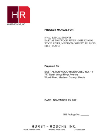
Wood bridges take on many forms, from the simplest log bridge to many types of trussed bridges– the style and design have evolved significantly over the years depending on technology,skill and availability of materials. “Covered Bridges and the Birth of American Engineering”(Christianson et al., 2015) explores the designs of over eighteen different types of wood trussconfigurations used historically for wood bridges including the most basic king post trusses tomore complicated town lattices and structurally efficient Pratt trusses. Truss bridges with thetrusses above the deck (so called ‘though-truss’) provide a great opportunity to build a roof overthe roadway. Trussed wood bridges from the 18th and 19th centuries had spans in the range of30 m to 60 m (100 to 200 feet). The presence of the roofs is the main reason these bridges stillexist today – the roof protects the wood structure beneath it from rain, snow and sun.West Montrose Bridge, Ontario, D. MosesTrussed bridges allow for longer spans compared to simple girder bridges. Many examplesof trussed timber bridges for roadways have been built for well over a century. For those withno roofs, the structure below the deck is relatively protected from weathering, however thetimber members and connections above deck require attention to detail to provide drainage andlocalized protection of the structure.Ontario Wood Bridge Reference Guide3
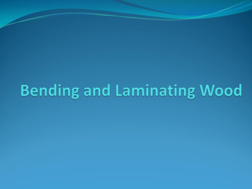
As described in detail in Timber Bridges Design, Construction, Inspection, and Maintenance(Ritter, 1990), the Howe truss was patented in the United States in 1840 based on stress analysiswhich was a major leap in timber bridge technology because it was based on more than ‘trial-anderror’ and introduced cast iron components to the design (chords and diagonals were timber andverticals were cast iron). Shortly after, the Pratt truss was patented, also using cast iron members.In Ontario, the Sioux Narrows Bridge, constructed in 1936 remained in service for almost 70years. It is a box Howe truss with a 64 m main span built from solid sawn Douglas fir timbers.As time passed, cast iron bridges became popular with less and less timber being constructed.Initially, timber bridges were about half the cost of cast iron bridges, but by the mid-1930’s, steelbridges could be built economically then reinforced concrete became more and more commonfor bridges. In the mid-twentieth century, most efforts into research and advancement of bridgeconcepts focussed on steel and concrete construction.In contrast to the mainstream, Ontario continued to build wood bridges, particularly in the northernparts of the province. Research activities continued at the Ontario Ministry of Transportationand Canadian universities where they pressed ahead with novel timber bridge designs duringthe 1970’s to 1990’s. Research using new engineered wood products such as glulam timber,parallel strand lumber (PSL), glass fibre reinforcing, high performance concrete and epoxiesand even composite concrete-log bridges continued to evolve (Krisciunas et al. 2010). Researchcontinues, though at a lesser pace, in Canada.Norwegian Bridge with member protection. Photo Credit: FPinnovations4 Ontario Wood Bridge Reference Guide
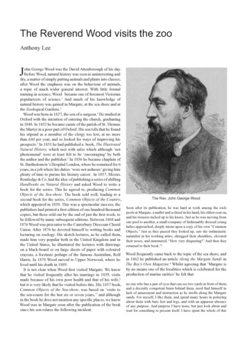
1.1.1. SCOPEPart 1 of this reference guide provides background on many topics related to wood bridgesincluding: Types of wood bridge systemsWood construction technologyWood bridge design considerations (national and provincial requirements)PrefabricationService life and durabilityBenefits (cost, construction cycle and sustainability)The topics are followed by examples of wood bridges from Canada and around the world.1.2. WOOD BRiDGE SyStEMS aND tEChNOLOGyThe following sections describe the various wood products and systems available, treatments,fasteners and hybrid systems.1.2.1. WOOD BRiDGE MatERiaLSSolid SawnSolid sawn members can be either dimensional lumber (sizes ranging from 38 mm x 89 mm to89 mm x 286 mm) used for deck laminations, or heavy timbers (ranging from 140 mm x 140 mmto 191 mm x 191 mm) for girders or floors beams.Glued-laminated timber (glulam)Glulam is typically made of dimensional lumber (38 mm thick) and glued together to formdeep members (See Figure 1.2.1.1.) that are more economical than using a large solid sawnlumber. Glulam is commonly used for stringers or girders, but can also be placed on its side tomake a glulam deck or concrete-glulam composite deck. Glulam can also be curved and forstandard glulam laminations they can be curved to a radius as small as 8.4 m – smaller radiican be achieved with thinner (non-standard) laminations (designers should be aware that not allsuppliers can supply thinner laminations and that it will be more expensive).Ontario Wood Bridge Reference Guide5
Figure 1.2.1.1. Glulam Member (Source: Figure 31L, section 4.1, FPi/tWBC)Laminated veneer lumber (LVL)LVL is manufactured from veneers all oriented in one direction. LVL is commonly produced in44 mm wide sections. LVL is approved for dry use only (i.e. for outdoor conditions it cannotbe exposed and must be adequately protected). In wood bridge applications, LVL is usuallyused for stressed T- or box-sections (see Section 2.2) but must be carefully protected frommoisture.Parallel Strand Lumber (PSL)Parallel strand lumber is a structural composite lumber (SCL) developed in Canada in the 1980’sand became commercially available in 1990. PSL is made from the same veneers as LVL, butthe veneers are sliced into thin long strands (approximately 3 mm x 12 mm x 1000 mm long)prior to pressing. The strands are pressed together with a resin. PSL can be treated but isnormally covered by a protective wearing surface. PSL can be built into in T- or box-sections.CompositesThe most common composite material used for wood bridges is a concrete-wood laminateddeck. The two materials are mechanically bonded to act as one member. See Section 1.2.2 formore detail.6 Ontario Wood Bridge Reference Guide
1.2.2. WOOD BRiDGE SyStEMSThe following sub-sections describe the various bridge systems used in wood bridges as theypertain to decks, the super structure, and the sub-structure.1.2.2.1. DECkSDecks are a crucial component of bridges, not only for structural strength, but also for protectionof the bridge substructure. For information on protection and treatment of decks, see Section1.4. There are many different types of decks used for wood bridges, as follows:Longitudinal nail-laminated (LNL) DecksLongitudinal nail-laminated decks are built from dimensional lumber laid side-by-side and nailedtogether to form a wood deck (or slab). Wood laminations span in the same direction as the flowof traffic. Lumber used for the deck ranges from 38 to 89 mm in thickness by 89 to 286 mm indepth. Most commonly available lengths are up to 4.9 m. This is also applicable for TNL, LSL,TSL, and WCC decks (described below).The use of longitudinal nail-laminated decks in Canada is limited due to the common occurrenceof deck delamination. Deck delamination can occur in LNL decks from some planks receivingmore load than adjacent planks directly under wheel loads. These planks will deflect more underthe higher concentrated load, causing the nails to bear more heavily and partially withdraw,effectively loosening the deck and delaminating the planks.Longitudinal nail-laminated decks span along the length of the bridge, in the direction of trafficflow and between supports.transverse nail-laminated (tNL) decksTransverse nail-laminated (TNL) decks are similiar to longitudinal nail-laminated (LNL) decksbut span across the width of the bridge. TNL decks are also built from dimensional lumberlaid side-by-side and nailed together to form the wood deck (or slab). Wood laminations spanperpendicular to the flow of traffic. TNL decks are more common than LNL decks since theyare less susceptible to delamination. Unlike an LNL deck, the TNL deck requires support fromgirders or stringers. Figure 1.2.1.2. illustrates the difference between LNL and TNL decks.Ontario Wood Bridge Reference Guide7
Figure 1.2.1.2. Longitudinal and transverse laminated decks(Photo credit courtesy of the Canadian Wood Council’s Wood Highway Bridges (1992))Longitudinal stress-laminated (LSL) decksLongitudinal stress-laminated decks are built from dimensional lumber laid side-by-side andnailed together to form a wood deck. In addition to the nailing, post-tensioned steel bars areinstalled through the deck. The post-tensioning helps to reduces plank delamination andimproves load sharing. Holes are pre-drilled through the wood planks and pressure treatedafter drilling for improved durability. LSL deck are more common than TSL decks (See Figure1.2.1.3.).8 Ontario Wood Bridge Reference Guide
Figure 1.2.1.3. Stress-laminated deck(Photo credit courtesy of the Canadian Wood Council’s Wood Highway Bridges (1994))Transverse stress-laminated (TSL) decksTransverse stress-laminated decks are built from dimensional lumber laid side-by-side and nailedtogether to form a wood deck. In addition to the nailing, post-tensioned steel bars are installedthrough the deck. Very few wood bridge decks use TSL decks. TSL is similiar to the LSL deck,but the post-tensioning bars are positioned in the same direction as the flow of traffic. This isproblematic as it means the anchorage point is located under the road (higher chances of contactwith salt and water) making it difficult to access for re-tightening and maintenance of the bars.Wood-concrete composite (WCC) decksWood-concrete composite decks are built from dimensional lumber laid side-by-side and nailedtogether to form a wood deck. The laminations can be either longitudinal or stress-laminated.The concrete is mechanically bonded to the laminated wood deck, to create a composite slab.(See Figure 1.2.1.4. below). The concrete provides a buffer between the vehicle wheels andwood planks, and provides better load distribution to the wood planks (significantly reducingthe likelihood of plank delamination). While the wood laminations are not affected by road salts,the concrete portion is susceptible to salts and must be designed and protected appropriately.Detailing between the concrete and wood is also required to ensure that water does not gettrapped between the two material interfaces.Figure 1.2.1.4. Wood-concrete composite deck(Photo credit courtesy of the Canadian Wood Council’s Wood Highway Bridges (1994))Note that other composite concrete-wood deck systems have been developed in other countries,typically using a connector between the wood and concrete for shear transfer with considerationof thermal and swelling changes in the materials.Ontario Wood Bridge Reference Guide9
Floor beam decksThe most common form of construction for floor beam decks are solid sawn timbers. Thesystem consists of a plank surface on heavy timbers oriented transversely and supported onlongitudinal wood or steel girders (See Figure 1.2.1.5. below). The decks are most commonlyfound in park and forest roads and municipal roads. Floor beam bridges can support heavyloads, but the planks may need replacing every few years. Typical floor beams are 184 x 184mm or 200 x 250 mm (depending on girder spacing). Typical planks sizes are 64 x 184 mm upto 100 x 250 mm.Figure 1.2.1.5. Floor beam deck (Moses Structural Engineers Inc.)Two-layer plank decksThe most common form of construction of two-layer plank decks are solid sawn timbers. Thissystem consists of two alternating layers of planks supported on floor beams. The two layers helpto provide a more dimensionally stable deck and better load distribution (See Figure 1.2.1.6.).10 Ontario Wood Bridge Reference Guide
Figure 1.2.1.6. Two-layer plank deck(Photo credit courtesy of the Canadian Wood Council’s Wood Highway Bridges (1994))1.2.2.2. SuPEr STruCTurESLog beamsPerhaps the oldest method of
Timber bridges have a long history of construction and use throughout North America, including Ontario, for roadways, railways and logging roads. The Canadian Highway Bridge Design Code (CHBDC), together with the Canadian Wood Council publication Wood Highway Bridges from 1992 are typically referenced by