Transcription
10Pneumatic, Hydraulicand P&ID DiagramsThis chapter goes through the steps for creating Piping &In this chapterInstrumentation (P&ID) and Hydraulic drawings but the same Setting Up HydraulicDrawings Inserting HydraulicSchematic Symbols Creating Pipes Completing the HydraulicDrawing Setting Up Your P&IDDrawing Inserting P&ID SchematicSymbols Creating Pipesworkflow can be applied for Pnuematics. Once your drawing is created, you can use the regular tools in the AutoCADElectrical software to modify your drawing.227
Setting Up Hydraulic DrawingsUse the Project Manager to manage your hydraulic drawings. From here youcan create a new drawing and modify any drawing properties.Create a new drawing1 In the Project Manager, right-click the project name, and select Properties.2 In the Project Properties Project Settings dialog box, click Default toswitch on all paths for pneumatic, hydraulic and P&ID schematic libraries.3 Click OK.4In the Project Manager, click the Create New Drawing tool.5 In the Create New Drawing dialog box, specify:1DPH AEGS127HPSODWH Mouse over the edit box to verify AutoCAD Electrical.dwt is specified'HVFULSWLRQ Hydraulic ExampleClick OK.NOTE You can also Click OK-Properties to proceed to Drawing Propertiesdialog box if you want to set the component, wire number, cross-reference,style and drawing format settings.6 Select Tools Drafting Settings.228 Chapter 10 Pneumatic, Hydraulic and P&ID Diagrams
7 In the Drafting Settings Snap and Grid dialog box, turn on Snap andGrid and set the size of both to 0.125.8 Click OK.9Click the Drawing Properties tool.Projects Drawing Properties10 In the Drawing Properties Drawing Format dialog box, Scale section,make sure that the feature scale multiplier is set to 1.0 inch.11 Click OK.NOTE For metric unit, the following settings are recommended so that thewire connection points will be placed on the grids for easier drafting. Gridand Snap Size 2.5mm; Feature scale multiplier 20 (scale factor 20)12 Select Projects Toolbars Extra Libraries.NOTE You can also turn on the toolbar by right-clicking on any toolbar andselecting ACE: Extra Libraries.This toolbar has tools for inserting Pneumatic, Hydraulic and P&IDcomponents.Inserting Hydraulic Schematic SymbolsThe hydraulic symbol library in AutoCAD Electrical includes filters, valves,cylinders, pressure switches, motors, pumps, meters, restrictors, quickdisconnects, flow arrows and more. The hydraulic symbol library consists ofall the hydraulic symbols and is found at \Program Files [(x86)]\Autodesk\Acade{version}\Libs\hyd iso125.Insert hydraulic symbols1Click the Insert Hydraulic Component tool.Inserting Hydraulic Schematic Symbols 229
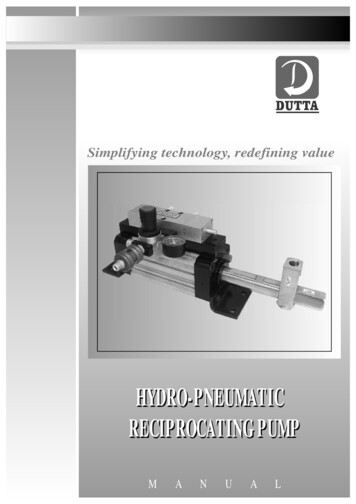
2 In the Insert Component: Hydraulic Symbol dialog box, select the checkbox for Vertical.3In the Insert Component: Hydraulic Symbol dialog box, click theGeneral Valves icon.4In the Hydraulic: General Valves dialog box, click Shut Off ValveOpen.5 Respond to the prompts as follows:6SHFLI\ LQVHUWLRQ SRLQWSelect to place the valve in the upper left corner of your drawing6 In the Insert/Edit Component dialog box, specify:&RPSRQHQW 7DJ VAL2Click OK.7 Repeat steps 1 - 3.8In the Hydraulic: General Valves dialog box, click Checkvalve FlowLeft.9 Respond to the prompts as follows:6SHFLI\ LQVHUWLRQ SRLQWSelect to place the check valve below the shut off valve10 In the Insert/Edit Component dialog box, click OK.11Click the Insert Hydraulic Component tool.12In the Insert Component: Hydraulic Symbol dialog box, clickMotors & Pumps.13In the Hydraulic: Motors and Pumps dialog box, click FixedDisplacement.230 Chapter 10 Pneumatic, Hydraulic and P&ID Diagrams
14In the Hydraulic: Fixed Displacement dialog box, clickUni-Directional Pump.15 Respond to the prompts as follows:6SHFLI\ LQVHUWLRQ SRLQW Select to place the pump below the check valve16 In the Insert/Edit Component dialog box, specify:&RPSRQHQW 7DJ Hydraulic Oil PumpClick OK.17 Insert another Shut Off Valve Open below the Hydraulic Oil Pump.18Click the Insert Hydraulic Component tool.19In the Insert Component: Hydraulic Symbol dialog box, click Filters.20In the Hydraulic: Filters dialog box, click Filter.21 Respond to the prompts as follows:6SHFLI\ LQVHUWLRQ SRLQW Select to place the filter below the shut off valve22 In the Insert/Edit Component dialog box, specify:&RPSRQHQW 7DJ FI2Inserting Hydraulic Schematic Symbols 231
'HVFULSWLRQ /LQH FilterClick OK.232425Click the Insert Hydraulic Component tool.In the Insert Component: Hydraulic Symbol dialog box, clickMiscellaneous.In the Hydraulic: Miscellaneous dialog box, click Reservoir.26 Respond to the prompts as follows:6SHFLI\ LQVHUWLRQ SRLQW Select to place the reservoir below the filter27 In the Insert/Edit Component dialog box, click OK.232 Chapter 10 Pneumatic, Hydraulic and P&ID Diagrams
Creating PipesIn the AutoCAD Electrical application, we use different types of wires torepresent the type of running pipes that allows water or oil flows from oneinstrument to another. Let's start by setting up the type of wires for pipe runs.Insert wires as pipes1Expand the Insert Wire tool, and then click the Create/Edit WireType tool.Wires Create/Edit Wire Type2 In the Create/Edit Wire Type dialog box, specify::LUH &RORU RED6L]H 20The Layer Name is automatically created. The name RED 20 is assignedto the wire layer you are creating.3 Click Color.4 In the Select Color dialog box, select red and click OK.5 Click Linetype.6 In the Select Linetype dialog box, select Continuous and click OK.7 In the Create/Edit Wire Type dialog box, specify::LUH &RORU GREEN6L]H 10&RORU Green/LQHW\SH Hidden28 Select RED 20 in the grid and click Mark Selected as Default.Creating Pipes 233
9 Click OK.10Click the Insert Wire tool.Wires Insert Wire11 Respond to the prompts as follows:6SHFLI\ ZLUH VWDUW RU ZLUH7\SH ; VKRZ FRQQHFWLRQV@Enter X and press ENTER234 Chapter 10 Pneumatic, Hydraulic and P&ID Diagrams
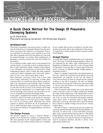
6SHFLI\ ZLUH VWDUW RU ZLUH7\SH ; VKRZ FRQQHFWLRQV@Select the bottom of the shut off valve6SHFLI\ ZLUH HQG RU 6FRRW 7 ZLUHW\SH ; VKRZ FRQQHFWLRQV@Select the top of the check valve12 Continue inserting wires connecting the components together. Right-clickto exit the command.Your drawing should look like the following.Creating Pipes 235
NOTE You can also insert the vertical or horizontal pipes first and then insertthe components onto the pipe, one at a time.13Click the Insert Hydraulic Component tool.14 In the Insert Component: Hydraulic Symbol dialog box, select the checkbox for Vertical.15In the Insert Component: Hydraulic Symbol dialog box, clickPressure Relief Valves.16In the Hydraulic: Pressure Relief Valves dialog box, click N.C.Pressure Relief Valve with Preset -1.236 Chapter 10 Pneumatic, Hydraulic and P&ID Diagrams
17 Respond to the prompts as follows:6SHFLI\ LQVHUWLRQ SRLQW Select to place the valve to the right of the pump18 In the Insert/Edit Component dialog box, specify:&RPSRQHQW 7DJ VAL4'HVFULSWLRQ /LQH Pressure ReliefClick OK.19Click the Insert Wire tool.Wires Insert Wire20 Respond to the prompts as follows:6SHFLI\ ZLUH VWDUW RU ZLUH7\SH ; VKRZ FRQQHFWLRQV@Enter X, press ENTER6SHFLI\ ZLUH VWDUW RU ZLUH7\SH ; VKRZ FRQQHFWLRQV@Press SHIFT right-click and select Midpoint from the menu, then select themidpoint on the pipe between the pump and the shut off valve above it6SHFLI\ ZLUH HQG RU 9 VWDUW 9HUWLFDO RUL]RQWDO &RQWLQXHVWDUWDrag the pipe to the right so that it is directly above the pressure relief valve,drag the pipe down and click the top connection point on the pressure reliefvalveYou now need to insert a pipe that connects the end of the valve backto the pump.Creating Pipes 237
TIP Make sure that Snap is turned off and that the Wire Layer is set toGREEN 10.6SHFLI\ ZLUH VWDUW RU ZLUH7\SH ; VKRZ FRQQHFWLRQV@Select the bottom connection point on the pressure relief valve6SHFLI\ ZLUH HQG RU 9 VWDUW 9HUWLFDO RUL]RQWDO &RQWLQXHVWDUWDrag the pipe down and to the left, click the connection point at the bottom ofthe pump, right-clickCompleting the Hydraulic DrawingThe rest of the hydraulic drawing consists of inserting a Pressure Gauge andCheck Valve at the left side of the pump and then inserting devices (Cylinder;Restrictors; Filter; Check valve and 2-ways valve) along the top of the drawing.NOTE During insertion, clear the Vertical option in the Insert Component: HydraulicSymbols dialog box.Insert components1Click the Insert Hydraulic Component tool.238 Chapter 10 Pneumatic, Hydraulic and P&ID Diagrams
2In the Insert Component: Hydraulic Symbol dialog box, clickMeters.3In the Hydraulic: Meters dialog box, click Pressure Gauge.4 Respond to the prompts as follows:6SHFLI\ LQVHUWLRQ SRLQWSelect to place the pressure gauge to the far left (and slightly above) of the pump5 In the Insert/Edit Component dialog box, specify:&RPSRQHQW 7DJ MTR1'HVFULSWLRQ /LQH Pressure GaugeClick OK.67Click the Insert Hydraulic Component tool.In the Insert Component: Hydraulic Symbol dialog box, clickGeneral Valves.In the Hydraulic: General Valves dialog box, click Shut Off Valve8Open.9 Respond to the prompts as follows:6SHFLI\ LQVHUWLRQ SRLQWSelect to place the valve to the right of the pressure gaugeCompleting the Hydraulic Drawing 239
10 In the Insert/Edit Component dialog box, click OK.11 Set the wire layer to RED 20.12Click the Insert Wire tool.Wires Insert Wire13 Respond to the prompts as follows:6SHFLI\ ZLUH VWDUW RU ZLUH7\SH ; VKRZ FRQQHFWLRQV@Select the right connection point on the pressure gauge6SHFLI\ ZLUH HQG RU &RQWLQXH@Drag the pipe to the right and click the left connection point on the valve6SHFLI\ ZLUH VWDUW RU 6FRRW ZLUH7\SH ; VKRZ FRQQHFWLRQV@Select the right connection point on the valve6SHFLI\ ZLUH HQG RU &RQWLQXH@Drag the pipe to the right and click the vertical pipe, right-click240 Chapter 10 Pneumatic, Hydraulic and P&ID Diagrams
14Click the Insert Hydraulic Component tool.15 Insert and place the devices listed below as shown in the followingillustration. In the Insert/Edit Component dialog box, click OK after eachinsertion.NOTE You can also insert the vertical or horizontal pipes first and then insertthe components onto the pipe, one by one.IconSymbol to Insert2 Way Valves Solenoid Spring Return -1(insert as Vertical symbol)General Valves Checkvalve Flow Left (insert as a Vertical symbol)Completing the Hydraulic Drawing 241
IconSymbol to InsertFilters Filter (insert as a Vertical symbol)Restrictors Restrictor with Variable Output FlowRestrictors By-Pass Flow Regulator with Variable Output FlowCylinders Single Acting Single Ended Piston RodTIP Align the components horizontally and vertically using the Align tool tomake inserting the pipes easier.242 Chapter 10 Pneumatic, Hydraulic and P&ID Diagrams
16Click the Insert Wire tool.Wires Insert Wire17 Connect the pipes from one control device to another as illustrated.1819Click the Insert Hydraulic Component tool.In the Insert Component: Hydraulic Symbol dialog box, clickGeneral Valves.In the Hydraulic: General Valves dialog box, click Checkvalve Flow20Left.21 Respond to the prompts as follows:6SHFLI\ LQVHUWLRQ SRLQW Select to place the valve below the restrictorCompleting the Hydraulic Drawing 243
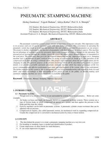
22 In the Insert/Edit Component dialog box, click OK.23Click the Insert Wire tool.Wires Insert Wire24 Connect the pipes as shown.244 Chapter 10 Pneumatic, Hydraulic and P&ID Diagrams
The hydraulic schematic diagram is complete.If you want to create a pneumatic drawing, use the Insert PneumaticComponents tool on the Extra Libraries toolbar. Refer to the pneumaticdemo drawing file (Demo03.dwg) in the "Extra Library Demo" project.Setting Up Your P&ID DrawingUse the Project Manager to manage your P&ID drawings. From here you cancreate a new drawing and modify any drawing properties.Create a new drawing1In the Project Manager, click the Create New Drawing tool.2 In the Create New Drawing dialog box, specify:1DPH AEGS13Setting Up Your P&ID Drawing 245
7HPSODWH Mouse over the edit box to verify AutoCAD Electrical.dwt isspecified'HVFULSWLRQ P&ID ExampleClick OK.NOTE You can also Click OK-Properties to proceed to Drawing Propertiesdialog box if you want to set the component, wire number, cross-reference,style and drawing format settings.3 Select Tools Drafting Settings.4 In the Drafting Settings Snap and Grid dialog box, turn on Snap andGrid and set the size of both to 0.125.5 Click OK.6Click the Drawing Properties tool.Projects Drawing Properties7 In the Drawing Properties Drawing Format dialog box, Scale section,make sure that the feature scale multiplier is set to 1.0 inch.8 Click OK.NOTE For metric unit, the following settings are recommended so that thewire connection points will be placed on the grids for easier drafting. Gridand Snap Size 2.5mm; Feature scale multiplier 20 (scale factor 20)Set up wire layers1Expand the Insert Wire tool, and then click the Create/Edit WireType tool.Wires Create/Edit Wire Type2 In the Create/Edit Wire Type dialog box, click in the Wire Type #2 rowand specify::LUH &RORU RED6L]H 25246 Chapter 10 Pneumatic, Hydraulic and P&ID Diagrams
The Layer Name is automatically created. The name RED 25 is assignedto the wire layer you are creating.3 Click Color.4 In the Select Color dialog box, select red and click OK.5 Click Linetype.6 In the Select Linetype dialog box, select Continuous and click OK.7 Click Lineweight.8 In the Select Lineweight dialog box, select 0.30 and click OK.For this example, you need to create three more wire types (two yellowwire layers and one green wire layer) using the Create/Edit Wire Typedialog box.9 In the Create/Edit Wire Type dialog box, specify:Wire Type #3:LUH &RORU YELLOW6L]H 15&RORU Yellow/LQHW\SH Continuous/LQHZHLJKW defaultWire Type #4:LUH &RORU YELLOW6L]H 10&RORU YellowWire Type #5:LUH &RORU G
Inserting Hydraulic Schematic Symbols The hydraulic symbol library in AutoCAD Electrical includes filters, valves, cylinders, pressure switches, motors, pumps, meters, restrictors, quick disconnects, flow arrows and more. The hydraulic symbol library consists of all the hydraulic symbols and is found at \Program Files [(x86)]\Autodesk\AcadeFile Size: 309KBPage Count: 28People also search forsolenoid valve p&id symbolpneumatic symbols chart with meaningspneumatic quick connector symblepneumatic symbols chart .dwgHYDRAULICS SWITCHES DIAGRAMS L pnematic quick connector legend