Transcription
Introduction to PneumaticConveying of SolidsKarl JacobThe Dow Chemical CompanyEngineering Sciences/Solids ProcessingMidland, Michiganjacobkv@dow.com
Goals for this webinar Understand various modes of conveying of solids Learn how to decide on conveying configuration Examine key aspects of design of conveying systems Recognize the various conveying system components Learn how to approach common conveying problems
What is pneumatic conveying?Pneumatic conveying is the movement of solidsthrough pipe using gas (usually air) as the motiveforce. It differs from hydraulic or slurry conveying inthat the gas expands continuously along the pipelength. The flow regime in the pipe depends greatlyon the ratio of solids to gas and the particlecharacteristics.
Why use pneumatic conveying tomove bulk solids? With the appropriate choice of system, material can be transported withminimal degradation Little or no exposure of the product to the environment Can transport relatively long distances (several thousand feet) Excellent for multiple sources and multiple destinations Ability to transport material which might be air, moisture, etc. sensitive Compared to mechanical conveyors, relative ease in system routingespecially elevation changes Interfaces well with a variety of transportation modes – truck, railcars,ships High reliability of system with comparatively few moving parts
Potential disadvantages Product degradation as a result of incorrectlydesigned system Pipe/component wear Not suitable for long distance (beyond a fewthousand feet) conveying – it is difficult to overcomethe gas expansion issue!
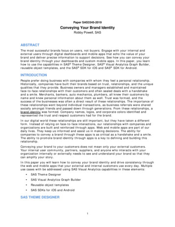
Conveying Flow RegimesHorizontal FlowDecreasing gas velocity
Conveying Flow RegimesHorizontal FlowDecreasing gas velocity
Pneumatic Conveying PhaseDiagram
Dense phase vs. dilute Dense phase Low velocity Low attrition High pressure Comparatively high cost Small pipe size High loadings Dilute phase High velocity Can have very high attrition Pressure typically 15 psig Low cost Larger pipe size Low loadings ( 10)
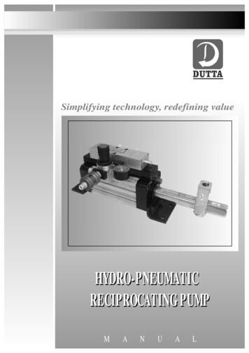
Actual Phase Diagram StyroporMaterial: Styropor (BASF)dp 2.385ρp 1050 kg/m3D 52.6 mm (SS)From Pneumatic Conveying of Solids, Marcus, et. al.
Basic design issues Number of sources and destinations? This isusually determined by plant conditions. Dense phase vs. dilute phase? Push vs. pull?Addressing each of the abovequestions will largely dictate thetype of system that needs to bedesigned.
Push vs. Pull Push – generally a pressure system operating aboveatmospheric pressure Pull – a vacuum system operating below atmosphericpressure - 7 psia is practical lower limit Choice of push vs. pull depends greatly # of sources anddestinations – some configuration
Push vs. Pull Selection Guide# of sources# of destinationsVacuum or pressuresystem?11either1ManyPressure preferredMany1Vacuum preferredManyManyeither
Typical Pull ConfigurationKey design issue is to insure that you can pull fromthe “longest” pipe configuration!
Typical Push ConfigurationIn parallel to the pull system, it is important that thesystem be designed to be able to handle the requiredconveying rate to the furthest destination.
Conveying Fundamentals In contrast to fluid flow with liquids, the conveying gasexpands along the length of the pipe and that has aconsiderable effect of the design and operation pneumaticconveying systems Contributions to pressure drop in a conveying system Head loss due to elevation change Solids acceleration Gas friction loss Solids friction loss Bend or elbow or fitting loss
Dilute phase pressure dropΔPtotal ΔPaccel ΔPlift ΔPbends ΔPair ΔPsolidsEach component of pressure drop can have a significant impact onconveying system performanceExamplesConveying of rubber – high solids frictionConveying of elastic materials – always acceleratingTruck unloading – high lift componentTortuous conveying path – high bend pressure drop
Pressure drop due to air In this particular case, we use theconventional friction factorformulation we learned in fluidmechanics If the conveying line is operated as“air only”, then this number isrelatively easy to check with either agauge or hand held manometer nearthe blower. Note that the gas density needs to beevaluated at each point in the pipe –consequently, design calculationsusually are done by breaking the lineinto many small pieces. Pair f g Lv2D2
Pressure drop due to particleacceleration The particles are required toaccelerate after being introduced intothe line – note that this is a one timeeffect in the calculation Here v and ug are the particle and gasvelocities respectively Pacc v g u p
Pressure drop due to lift Standard treatment here as we would expect Plift p (1 ) Hgε is the voidage and for dilute phase systems willtend to be 0.99 or greater
Pressure drop due to bends Bends are quite common inconveying systems andnumerous correlations have beendeveloped to calculate bendpressure drop Note that when measuringpressure drop in the field, it needsto be measured several pipediameters downstream of the exitof the elbow to properly accountfor particle reacceleration afterthe bend. Pbend B(1 ) g v2DB is a bend factor usually takenas being 0.5 for a long radiuselbow2
Pressure drop due to solids friction The solids friction componentmirrors that of gas pressure lossexcept for now we have a special“solids friction factor” There are some existingcorrelations for λZ both in thevertical and horizontal direction The friction factor can also bedetermined from either pilot plantwork or by careful analysis of aproduction plant Psolids Z g Lv2DNote the impact of systemloading on pressure drop!2
Saltation When the gas velocity is slowly decreased during dilute phase conveying,material will begin to deposit or “salt out” at the bottom of horizontal sections ofthe conveying system. Saltation is loading dependent – typically the higher the loading, the higher thesaltation velocity No single correlation predicts saltation across all gas and particle parameters For plastic pellet systems, Rizk’s equation has been found to work well Fine particle systems tend to have cohesion and so, although it seemssomewhat counterintuitive, saltation velocity will increase a function of particlesize. This effect is well described by the equation of Matsumoto (1977).
Saltation Equation - RizkRizk’s equation1 vs 10 gD whereμ is the phase ratio (kgs of solid/kg of gas)vs is the saltation velocityD is the pipe diameterκ 1.1dp 2.5δ 1.44dp 1.96Note that the particle size, dp, must be in millimeters!!!
How do we design a system? Select configuration – push vs. pullDetermine preliminary layoutGuess pipe/tube sizeCalculate saltationEstimate pressure dropCalculate volume of blowerSelect blowerCalculate pressure drop – check if pressure drop, velocity and pipe size agreewith estimates – if not, iterate based on initial solution
Conveying SystemComponents Air Movers Feed systems Pipe/Tube Dust Collector Couplings/Flanges
Air Movers Rotary Lobe Blowers – often called “Roots” blowers Fans Compressors
Typical air mover performancecurvesCompressorvolumeBlowerFanpressure
Lobe Blower PerformanceCurvesPressureVacuum
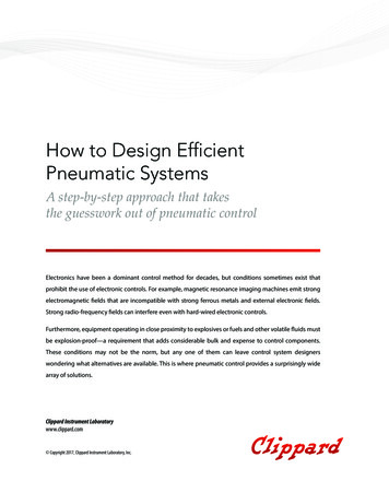
Rotary Lobe BlowerThese are true positive displacement devices.Some suppliers will provide a tri-lobe model in order to cut down on thepulsations in the flow.Diagram from Roots
Common feed systems Rotary valve (also star valve) – the most common feeder usedin conveying systems – considerable versatility – good turnup/turn down Slide valves Screw feeder Double flapper valves Venturis Pneumatic wands
Rotary ValvesTypical cutaway view of acommercial rotary valve. Can be connected to fixed speed or variable speed drive Always need to be concerned about tip wear – typical new clearancesare 4-6 mils Need to consider valve leakage during design – leakage cansabotage an otherwise well-designed tary-valve.asp
Pipe & Tube Light gauge (Sch. 10) pipe or tube is routinely used forconveying systems Materials of construction include stainless steel, CS andaluminum Aluminum is frequently used in the conveying of plastics Particular attention needs to be given to bends/elbows whereerosive wear can be an issue, even with soft products (e.g.polymers) With the wide selection of pipe and tube sizes, it affords theconveying system designer an excellent opportunity foroptimal system design
Couplings/Flanges Couplings represent an inexpensive and easy choice for conveying system tubeconnections. They are typically used on tube systems and come in a variety ofstandard sizes. They are relatively easy to assemble/disassemble. However,if stressed laterally, they can be prone to misalignment. By comparison, flanges are used in pipe systemsand commonly used on higher pressure ( 15 psig)dense phase systems. A number of companies nowsell self-aligning flanges which help to minimize offgrade particles and conveying system wear.
Dense phase conveying Dense phase is recommended when product attrition andproduct quality demands our utmost attention Typically is characterized by low velocity conveying Conveying mode depends greatly on particle characteristics Pressures in systems routinely between 1 and 6 barg A priori prediction of performance extremely difficult System performance is all about control of plugs of material Stresses due to large plugs in piping systems can be difficultto control
Conveying regimes for densephase pneumatic conveying Three reasonably distinct conveying modes are observed when conveyingbulk solids in dense phase Large materials like plastic pellets will naturally form slugs of materialin the conveying line interspersed between pockets of air Medium sized granular materials (example 100-1000 μm) do not makewell formed slugs in the line – the conveying is characterized by theformation and degradation of degenerate slugs in the line – some typeof air assist is required to maintain slug control. Care must be takenthat too much air isn’t added to the line causing the system to be indilute phase Fine materials ( 50 μm) will naturally form very long slugs in the line,consequently some sort of plug breaking mechanism must beinstalled in order that the pressure drop across the system does notbecome inordinately high
Boosters – Air ics/systems/conventionalfill.gif
Commonly encounteredproblems Increasing conveying system throughput Attrition/floss formation/pipe erosion Line failure in dense phase systems Plugging due to poor layout
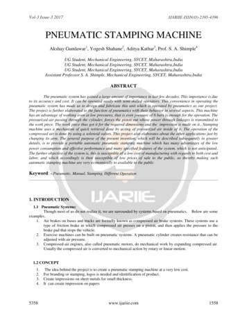
Increasing system throughput Quite commonly, the capacity of a dilute phase conveyingsystem needs to be increased. Take, for example, a systemoperating at 12 psig, near the relief of the positivedisplacement blower. The velocity at the pick-up point(where the solids are introduced into the system) is 5000 fpm,well above the saltation velocity of 4000 fpm. What shouldshe or he do?
Phase Diagramm3m3 m2 m1m2Pressure dropm1Air only pressure dropgas velocityBA
Attrition/Floss formation Attrition is a key issue in the conveying of solids and can lead to any of thefollowing issues: Poor product performance Environmental, Safety and Health issues Changes in the flow properties of material Polymeric materials can be problematic due to the formation of either dust orfloss (also streamers or angel hair) The key in these situation is velocity control!! Typically attrition is a strongfunction of velocity. If the velocity in a dilute phase system can be reduced,this represents a legitimate option for reduction of attrition.Attrition α velocity3-5
Line failure in dense phasesystems This can be a very SERIOUS issue. During the dense phase conveying, it is not unusual to see the line moving orvibrating as slugs make their way through the conveying line. Tremendous forces are encountered as a plug switches directions, particularlyaround horizontal elbows – example, in large systems it is not uncommon tosee individual plug weights on the order of 500 lbs. These forces have been and can be very destructive (up to and includingcomplete line failure) In this particular case, it is highly recommended to work with a reputableconveying supplier who understands the issues around this problem
Plugging due to line layout Often piping designers assume that conveying systems are just likeconventional liquid and gas piping runs, consequently it is not unusual tohave multiple elbows back to back The particles need some distance to reaccelerate Even though the system may be designed to be above the saltationvelocity, the particle will simply fall out of suspension and the line willplug Two choices to fix this type of problem Increase the gas flow – downsides are potential attrition and reduction insystem throughput Re-route the line – this is not always the most economical in the short termbut represents the best solution to the problem
Poll Question We've had three webinars this year on various topics ofsolids processing/particle technology (introduction, bins andhoppers, pneumatic conveying). Our next webinar isscheduled for January 19, 2011. Which of the followingtopics would you most like to hear about next time (pleasevote for one)? Fluidization/fluid bed technology Gas solid separation (cyclones, dust collectors, bag houses,wet scrubbers) Classification of particles (screeners, air classifiers)
Summary With proper care and thought, pneumatic conveying systems can be designedand operated to give excellent performance with minimal product degradation There is considerable SCIENCE behind how these systems work Thanks for listening!!
What is pneumatic conveying? Pneumatic conveying is the movement of solids through pipe using gas (usually air) as the motive force. It differs from hydraulic or slurry conveying in that the gas expands continuously along the pipe length. The flow regime in the pipe depends greatly on the ratio of solids to gas and the particle characteristics.File Size: 1MBPage Count: 45