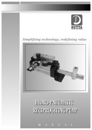
Transcription
How to Design EfficientPneumatic SystemsA step-by-step approach that takesthe guesswork out of pneumatic controlElectronics have been a dominant control method for decades, but conditions sometimes exist thatprohibit the use of electronic controls. For example, magnetic resonance imaging machines emit strongelectromagnetic fields that are incompatible with strong ferrous metals and external electronic fields.Strong radio-frequency fields can interfere even with hard-wired electronic controls.Furthermore, equipment operating in close proximity to explosives or fuels and other volatile fluids mustbe explosion-proof—a requirement that adds considerable bulk and expense to control components.These conditions may not be the norm, but any one of them can leave control system designerswondering what alternatives are available. This is where pneumatic control provides a surprisingly widearray of solutions.Clippard Instrument Laboratorywww.clippard.com Copyright 2017, Clippard Instrument Laboratory, Inc.
A Compact, Economical SolutionModular air-logic systems are often a smart choice, especially for applicationswhere space is limited.Modular air-logic systems are often a good betwhen a compact, economical solution is a must.They typically consist of a series of valves mountedonto standard manifold subplates.Only a few manufacturers offer modular, manifoldmounted pneumatic control systems. For instance,Clippard offers a pneumatic programmablecontroller—a sequential controller that providesstep-by-step system operation. It consists of aclear acrylic manifold for mounting sequencevalves and other such components in a compact,efficient package.Compared with discrete air-valve controlsystems, a modular system provides:Feedback signals provide positive, safe operation.If no signals are sent (due to a componentfailure, missing or jammed parts, and so on), thesequence stops and an indicator pinpoints whereto troubleshoot. Internal interlocks prevent out-ofsequence feedback signals. Simple plumbing and troubleshootingA pneumatic output signal at each step actuatesair-piloted devices, including power valves,hydraulic valves, pressure switches, and othercomponents that may control air cylinders. The lastsequence valve resets the system to repeat the cycleof operations. Lower air consumptionDESIGN BASICS No air locksModular systems can contain just a few valves ordozens, with many built-in functions to permit asystematic approach to circuit design. As with anycontrol system, it is essential to outline systemrequirements to save time and reduce the chancesof missing a critical step. Proven, reliable design Lower component costs A smaller total packageCompared to electrical-relay control,a modular system offers: An explosion-proof system withno danger of burnouts Lower power consumption Lower costs by eliminating solenoidsand relays A single air supply No heat buildup2The system is designed to automatically generatefeedback signals to initiate the next step whenan operation finishes. Many types of sensors cangenerate feedback signals, including limit valves,proximity sensors, pressure sensors, Hall-effectswitches, back-pressure cylinder sensors, andmanual pushbuttons.A Compact, Economical SolutionDesigners must also have a clear understandingboth of the sequence of operations (includingpressure, temperature, filtration, and otheroperating conditions) and the control requirements(including manual, automatic, start, stop, etc.). Asa final check of circuit operation, consider properactuation during all conceivable events. Thisincludes startup, shut down, loss of air, panic stopsin mid-cycle, restarts in mid-cycle, and controlduring any other event likely to occur.
Programming GuidelinesAfter defining the overall functions and requirements of a system, configure thesystem following some basic guidelines.First, label all components in the pneumatic circuit.We recommend labeling each cylinder with a letterof the alphabet, starting with A. The same holdsfor air motors and other controlled devices.Label the valve controlling the cylinder with thesame letter. Label the pilot of the valve that extendsthe cylinder (or activates a device) with a plussymbol, and the pilot of the valve that retracts thecylinder (or turns off a device) with a minus symbol.Label the limit sensor the cylinder rod strikeswith the letters LV (limit valve), the letter of thecylinder, and position of the sensor for extending orretracting. LVA , for example, would mean the limitvalve of an extended cylinder A.Second, list in detail every sequence of operation.This includes the action or control that initiates astep, what function takes place during that step,and the limit sensor that ends the operation. Notewhat position all actuators are in for every step.An example of a simple two-cylinder sequence isshown below (Table 1).Third, select components for the control system.Modular systems offer great flexibility becauseusers can incorporate multiple options whenselecting sequence valves. For instance, in thetwo-cylinder sequence example, five steps (extendTABLE 1and retract the two cylinders plus reset) require fivesequence valves.A basic valve could be used for each step, or youcould choose valves with special features. Forexample, the first two steps could use a valve thatprovides a sequence reset lock if the start button isheld down or if the limit valve LVA is locked down.Reset lock means the sequence will not reset tobypass the valve being actuated.After choosing components, assemble fittings andmodular valves into the subplate. Connect the airsupply and lines from the limit valves and electricalconnections from the Hall-effect sensors to theinlet connections. Finally, connect air lines from theoutlet to the air pilots of the power valves.Two-Cylinder SequencePower Valve APower Valve BLimit ValvesHall Effect SwitchesLVB–LVB LVA–LVB–LVA LVB TWO-CYLINDER SEQUENCEActuating ControlStepDescriptionFunctionLimit SensorStart Valve1Extend Cylinder A: Cylinder Position A , B-A LVA (limit valve)LVA 2Retract Cylinder A: Cylinder Position A-, B-A-LVA- (limit valve)LVA-3Extend Cylinder B: Cylinder Position A-, B B LVB (Hall effect switch)LVB 4Retract Cylinder B: Cylinder Position A-, B-B-LVB- (Hall effect switch)LVB-5Reset Sequence: Cylinder Position A-, B-Resetclippard.com3
Changing OperationsModular systems can be quickly tailored to meet specific requirements. Sequenceconditions can be altered or adapted to the application by using different controlmodules. Here’s a look at some common options.START OPTIONSIf the application demands an input for each cycleof operations, use a pushbutton input signal anda sequence valve that provides a reset lock if thebutton is held actuated.If continuous cycling is required, use a selectoror toggle valve at the input of the first stepalong with a valve that permits continuous cyclesequences. For applications requiring choosingbetween one cycle or continuous cycling, adda selector valve that determines the type ofoperation.Manual StartStart OptionsInput SM1SupplyA selector valve gives the option of one-cylinder operationor continuous cyclingSYSTEM SHUT-OFFSystemThese controls turn off the main air supply.This prevents harming people or product fromaccidental machine operation.If the system has large power valves, a pilotedthree-way main supply valve can control a specificmachine section. When electrical circuits arepart of the system, an air-piloted pres sure switchensures the system has electric power only if theair is on.Emergency StopSupplyTo Pressure ValvesSystem ShutoffPrevents accidental machine operation4Changing OperationsMULTIPLE INPUTSMULTIPLE OUTPUTSWhen two functions actuate at the same time, apiloted 3-Way valve (AND function) ensures bothfunctions are complete before the next step begins.When two (or more) functions start with the samestep, connect the output from that sequence stepto both power valves.
MULTIPLE FUNCTIONSFunctions that actuate twice during the sequencecall for the system to connect a shuttle valve (ORfunction) to the pilot of the power valve.Multiple FunctionsSM1OUTSM2OUTSM3OUTSM1OUTA shuttle valve to the pilot of a power valve lets afunction actuate twice during a sequence.DELAYSE-STOPApplications requiring a delay before a step canuse a delay-in module between the limit.Emergency-stop controls can halt systemoperations in several ways:1. Stopping the sequence onlyRESETThis control, when actuated, returns the sequenceto the start position. Reset can also place powervalves in a home position. A reset circuit shouldonly be used when the control is in manual mode.2. Stopping the sequence and relieving pressurefrom the power valves3. Stopping the sequence and activating resetcontrolsA latching mushroom-head button is commonlyused for the emergency-stop control because itgives users a positive response when activated.BACK PRESSURE SENSINGMany air-cylinder applications cannot usemechanical limit valves for sensing because ofphysical interference, temperature extremes, orother conditions. A method called back pressuresensing indicates cylinder position without limitvalves. For example, as a cylinder retracts, it createsa back pressure behind the piston. Restrictingexhaust air at the control valve further increasespressure and slows return of the cylinder rod.This back pressure holds the pilot down on aNormally-Open (NO) 3-Way valve. When the cylinderfully returns, back pressure diminishes at the pilotport of the Normally-Open 3-Way valve, letting aspring shift the valve to send a pneumatic signalto the next step. If the system requires a delay,substitute a delay-out module for the 3-Way valve.clippard.com5
To request a free Clippard Full-LineProduct Catalog, scan the code belowor fill out the form online at:clippard.com/link/gwwpClippard Instrument Laboratorywww.clippard.com Copyright 2017, Clippard Instrument Laboratory, Inc.
How to Design Efficient Pneumatic Systems A step-by-step approach that takes the guesswork out of pneumatic control. Modular air-logic systems are often a good bet when a compact, economical solution is a must. They typically consist of a series of valves mounted onto standard manifold subplates. Only a few manufacturers offer modular, manifold-mounted pneumatic control systems. For instance .