Transcription
Vol-3 Issue-3 2017IJARIIE-ISSN(O)-2395-4396PNEUMATIC STAMPING MACHINEAkshay Gundawar1, Yogesh Shahane2, Aditya Kathar3, Prof. S. A. Shimple4UG Student, Mechanical Engineering, SYCET, Maharashtra,IndiaUG Student, Mechanical Engineering, SYCET, Maharashtra,IndiaUG Student, Mechanical Engineering, SYCET, Maharashtra,IndiaAssistant Professor S. A. Shimple, Mechanical Engineering, SYCET, Maharashtra,IndiaABSTRACTThe pneumatic system has gained a large amount of importance in last few decades. This importance is dueto its accuracy and cost. It can be operated easily with semi-skilled operators. This convenience in operating thepneumatic system has made us to design and fabricate this unit which is operated by pneumatics as our project.The project is further elaborated to the function of pneumatics with their behavior in several aspects. This machinehas an advantage of working even at low pressures, that is even pressure of 6 bars is enough for the operation. Thepressurized air passing through the cylinder, forces the piston out whose power through linkages is transmitted tothe work piece. The work piece thus got it for the required dimensions and the impression is made on it. Stampingmachine uses a mechanism of quick retrieval done by acting of pressurized air inside of it. The operation of thecompressed air is done by using a solenoid valves. This project also elaborates about the other applications just bychanging its arm. The general purpose of the present invention, which will be described subsequently in greaterdetails, is to provide a portable automatic pneumatic stamping machine which has many advantages of the lowpower consumption and effective performance and many specified features of the system, which is not anticipated .The further objective of the system is, this is susceptible of a low cost of manufacturing with regards to both cost andlabor, and which accordingly is then susceptible of low prices of sale to the public, so thereby making suchautomatic stamping machine are very economically to available to the publicKeyword: - Pneumatic, Manual, Stamping, Different Operation1. INTRODUCTION1.1 Pneumatic Systems:Though most of us do not realize it, we are surrounded by systems based on pneumatics. Below are someexamples.1. Air brakes on buses and trucks are formally known as compressed air brake systems. These systems use atype of friction brake in which compressed air presses on a piston, and then applies the pressure to thebrake pad that stops the vehicle.2. Exercise machines can be built on pneumatic systems. A pneumatic cylinder creates resistance that can beadjusted with air pressure.3. Compressed-air engines, also called pneumatic motors, do mechanical work by expanding compressed air.Usually the compressed air is converted to mechanical action by rotary or linear motion.1.2 CONCEPT1.2.3.4.5358The idea behind the project is to create a pneumatic stamping machine at a very low cost.For branding or stamping, logos is needed and identification of product.Create impressions on sheet metals for small thickness.It can create impression on paperswww.ijariie.com1558
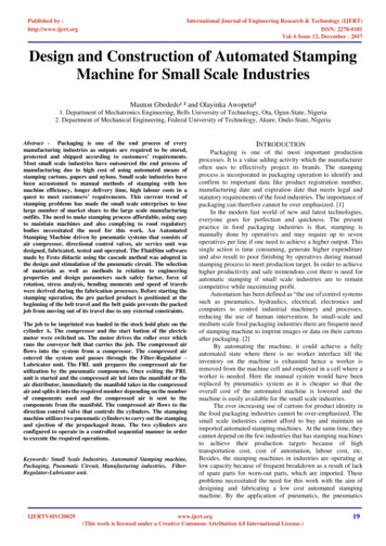
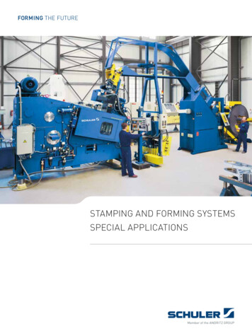
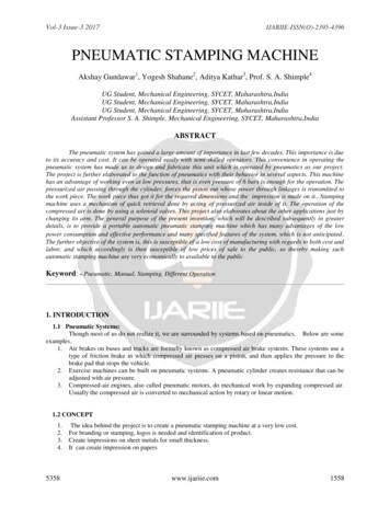
Vol-3 Issue-3 2017IJARIIE-ISSN(O)-2395-43962. ACTUAL PROJECT DIAGRAMFig -1: Actual Project Diagram2.1 WORKING1.2.3.4.5.5358When the power supply is ON, the compressor starts working the air is filtered and the air is passed tocompressor.The compressed air is passed through pipe to the double acting cyclinder at a required amount of pressureThrough double acting cylinder valve the piston is actuated up or down motion on work piece the operationis carried out.For different operations the time required is different ex.cutting, embossing, punching and stampingoperations.Based on the hand motion the valve is reversed and air passing to the cylinder valves which will be makingthe piston to reciprocate up the cylinder is a double acting cylinder.www.ijariie.com1559
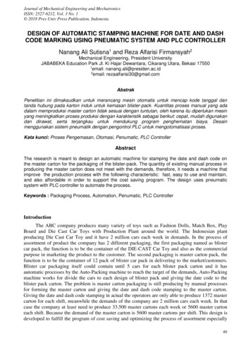
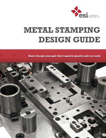
Vol-3 Issue-3 2017IJARIIE-ISSN(O)-2395-43963.DESIGN PARAMETERS STATEMENT FOR DESIGN:The Pneumatic stamping machine is to be designed to operate at the maximum pressure of 10 bar and the leveroperating force required is 150N, with the operating temperature of 2000 C. Cylinder Sizing Calculator The aircylinder sizing calculator below performs the following steps:Calculate the area of the cylinder piston Area Pi x r2 2. Multiply the piston area by the air pressure to be usedArea x Pressure Force OutputNote: The force output on the rod end of a cylinder will be slightly less due to the displacementof the rod. The real force output of a cylinder will be less than the theoretical output because ofinternal friction and external side loading. It is best to use a cylinder that will generate from 25Material: Al. fs 210kg/cm2Bolt material: M.S. ft 280 kg/cm2 Design a cylinder of internal diameter for Di 8 cm, Internalair pressure P 25 kg/cm Max. Ft 210kg/cm and max. fib 280 kg/cm.Fig:-2 Cylinder dimensionsFor safety purpose we will design the cylinder using factor of safety as Thereforet 4 x 0.2 0.8 cmTo find the outer diameter of the cylinder,Outer diameter Do Di 2 (t) 40mm WidthIn side diameter of cylinder, DI Do - ( 2 x width of packing) 40 - (2 x 2.5) 4 0 - 5 3 5 m mDo 40mmDI 35 mmMaximum presser 10kgf/cm2 145 psiPRESSURE MEASUREMENT5358www.ijariie.com1560
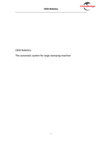
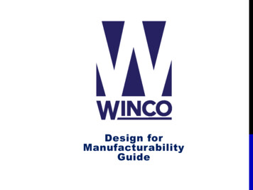
Vol-3 Issue-3 2017IJARIIE-ISSN(O)-2395-43961 Bar 100Kpa 100KNm-2 145 PSIFig-3 Punching parameterEquation: P F/AP 10 bar 1.01 N/mm2Diameter of piston d 40mmA (3.14 / 4) * (d *d) (3.14 / 4) * (40 * 40) 1256 mm2P F / A1.01 F / 1963F 1250 NF 125 Kg.So, we have selected pneumatic cylinder move 125 Kg. Of force at 10 bar pressure.5358www.ijariie.com1561
Vol-3 Issue-3 2017IJARIIE-ISSN(O)-2395-4396Fig-4 Double acting cylinderThe force exerted by double acting pneumatic cylinder on outstroke can be expressed as . The force exerted on instroke can be expressed asF p π (d12 - d22) / 4F 11.8 NWhereF force exerted (N)p gauge pressure (Pressure (kPa) 1 bar 100 kpa)d full bore piston diameter (m)d1 full bore piston diameter (m)Force output stroke 11.8 N4. ADVANTAGESPneumatic control systems are widely used in our society, especially in the industrial sectors for the driving ofautomatic machines. Pneumatic systems have a lot of advantages:A) Simple design1.The designs of pneumatic components are relatively simple.2.They are thus more suitable for use in simple automatic control systems.5358www.ijariie.com1562
Vol-3 Issue-3 2017IJARIIE-ISSN(O)-2395-4396B) High adaptability to harsh environment1.Compared to the elements of other systems, compressed air is less affected by high2.Temperature, dust, corrosion, etc.C) Safety1.Pneumatic systems are safer than electromotive systems because they can work in inflammable environmentwithout causing fire or explosion.2.Apart from that ,overloading in pneumatic system will only lead to sliding or cessation of operation.3.Unlike electromotive components, pneumatic components do not burn or get overheated when overloaded.D) Environmental friendly1)The operation of pneumatic systems does not produce pollutants.2)The air released is also processed in special ways.3)Therefore, pneumatic systems can work in environments that demand high level of cleanliness. One example isthe production lines of integrated circuits.E) Economical1.As pneumatic components are not expensive, the costs of pneumatic systems are quite low. Moreover, aspneumatic systems are very durable, the cost of repair is significantly lower than that of other systemsF) High effectiveness1.Many factories have equipped their production lines with compressed air supplies and movable compressors.2.There is an unlimited supply of air in our atmosphere to produce compressed air.3.Moreover, the use of compressed air is not restricted by distance, as it can easily be transported through pipes.4.After use, compressed air can be released directly into the atmosphere without the need of processing.G) High durability and reliability1.Pneumatic components are extremely durable and cannot be damaged easily.2.Compared to electromotive components, pneumatic components are more durable and reliable.5. DISADVANTAGESAlthough pneumatic systems possess a lot of advantages, they are also subject to many limitations.A. Relatively low accuracy1. As pneumatic systems are powered by the force provided by compressed air, their operation is subject to the volumeof the compressed air.2. As the volume of air may change when compressed or heated, the supply of air to the system may not be accurate,causing a decrease in the overall accuracy of the system.B. Low loading1. As the cylinders of pneumatic components are not very large, a pneumatic system cannot drive loads that are tooheavy.C. Processing required before use1. Compressed air must be processed before use to ensure the absence of water vapour or dust.5358www.ijariie.com1563
Vol-3 Issue-3 2017IJARIIE-ISSN(O)-2395-43962. Otherwise, the moving parts of the pneumatic components may wear out quickly due to friction.D. Uneven moving speed1. As air can easily be compressed, the moving speeds of the pistons are relatively uneven.E. Noise1. Noise will be produced when compressed air is released from the pneumatic components.6. APPLICATIONS:Automatic pneumatic stamping machine has various applications by which some may not be applied nowbut in further extension of this, the main application of this machine is stamping.1) Creating impression on metal sheets with small thickness.2) It can also be used as a punching machine as its pressure range is sufficient for it.3) It can create impression on paper and also on low ductile materials.4) In further extension it can also be used a sheet bending machine.7. CONCLUSIONThe general purpose of the present invention, which will be described subsequently in greater details, is toprovide a portable automatic pneumatic stamping machine which has many advantages of the low powerconsumption and effective performance and many specified features of the system, which is not anticipated. furtherobjective of the system is, this is susceptible of a low cost of manufacturing with regards to both cost and labor, andwhich accordingly is then susceptible of low prices of sale to the public, so thereby making such automatic stampingmachine are very economically to available to the public.8. REFERENCES[1]. “Hydraulic & pneumatics” by Shrinivasan[2]. “Pneumatic system” by S.R.Majumdar[3]. Introduction to Hydraulics and Pneumatics by S.IIango, V. Soundaranjan PHI Learning Pvt. Ltd., 2011.[4]. Hydraulic and Pneumatic Controls by K. Shanmu-gaSundaramS. Chand Limited, 2006.[5]. Hydraulics and Pneumatics by Andrew Parr, Butter-worth- Heinemann, 1999[6]. The 8051 Microcontroller and Embedded Systems by Muhammad Ali Mazida, Janice Gllipsce Mazida, RolinD. Mc Kinlay PEARSON Publications.[7]. Basic Electrical Engineering by DC KULSHRESHTHA; McGraw-Hill Education, 2011.[8]. www.janaics.com, provided about the required in-formation about the equipments to be preferable for themachine.[9]. www.fesco.com, provided information about the prices of the equipments of the stamping machine.5358www.ijariie.com1564
Automatic pneumatic stamping machine has various applications by which some may not be applied now but in further extension of this, the main application of this machine is stamping. 1) Creating impression on metal sheets with small thickness. 2) It can also be used as a punching machine as its pressure range is sufficient for it.Author: Yogesh Shahane, Akshay Gundawar, Aditya Kathar, S. A. ShimplePublish Year: 2017