Transcription
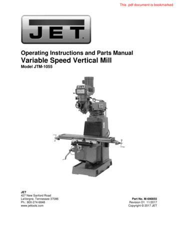
OPERATING INSTRUCTIONS & PARTS MANUALTEELWATER CIRCULATING PUMPSINDUSTRIALSERIESMODELS 1P899A THRU 1P903A, 2P432 THRU 2P436,2P609 THRU 2P612, 3P701 & 3P702FORM5S1375017820488/119/5MREAD INSTRUCTIONS CAREFULLY BEFORE ATTEMPTING TO INSTALL, OPERATE, OR SERVICE TEELPUMPS. PROTECT YOURSELF AND OTHERS BY OBSERVING ALL SAFETY INFORMATION AND ADDITIONALINSTRUCTIONS INCLUDED WITH THIS EQUIPMENT. FAILURE TO COMPLY WITH INSTRUCTIONS COULD RESULT IN PERSONAL INJURY AND/OR PROPERTY DAMAGE!RETAIN INSTRUCTIONS FOR FUTURE REFERENCE.DescriptionTeel water circulating pumps are designed for in-linemulti-stage zoning applications in hydronic heating andcooling systems for residential, commercial and/or industrial applications. May also be utilized in domesticwater pressure systems and OEM equipment requiringcirculation of liquids. All models have radially split pumpbodies; pump body can remain in line during repair ormaintenance, no need to disconnect piping whenservicing.Pump should t e used with liquid compatible with pumpconstruction materials.Figure 1WARNING: DO NOT USE TO PUMP FLAMMABLE EXPLOSIVE FLUIDS SUCH AS GASOLINE, FUEL OIL,KEROSENE, ETC., OR IN EXPLOSIVE ATMOSPHERES. FAILURE TO FOLLOW THIS WARNING CANRESULT IN PROPERTY DAMAGE OR PERSONALINJURY.UnpackingWhen unpacking the unit, inspect for any damage thatmay have occurred duhng transit. Check for loose,missing or damaged parts.Pump Construction1P903A2P432, 2P609I BronzeBrass BrassCopperBrassAlloy steelType 316 stainlesssteelCeramicCarbonCopperBuna NPARTBODYIMPELLERIMPELLER NUTIMPELLER WASHERSEAL PLATESHAFTSEAL SPRINGSEAL SEATSEAL RINGSEAL SLEEVESEAL ELASTOMERCOVER PLATE —MODEL1P899A, 1P900A1P901A, 1P902A2P434, 2P4352P4332P610, 2P611Cast ironCast ironPlated steeP BrassPlated steelBrassPlatedBrassPlated SteelPlated steelAlloy steelAlloy steelType 316 stainlessType 316 rCopperBuna NBuna N—-r2P436, 2P612,3P701, 3P702Cast ironBronzeBrassBrass—Alloy steelType 316 stainlesssteelCeramicCarbonCopperBuna NCast Iron 1P899A and 1P903A have polypropylene/40% glass-filled impellers. 1P900A, 2P432 and 1P901A have Norylimpellers.
FORM 5S1375MODELS 1P899A THRU 1P903A, 2P432 THRU 2P436, 2P609 THRU 2P612, 3P701 & 30208-230/4603P702V/2208-230/460THERMAL FACE TOF/LPH. AMPS PROTECTION FACE. 9.8M.9*13%Auto8 /2Auto5*4Auto111/22.8-2.9/IIV23Manual1.4513V2Auto1 ENGTHWIDTHFLANGE 1/211/29%21%2Full-load amps at 115/230 volts.PerformanceF L O W R A T E IN G P M B A S E D O N M A X I M U M P I P E S I Z E."rOTA L HEAD IN FEE1 SHUT71435482586OFF8910 11 1 2 1 3 1 4 15 16 17——1P899&1P9033028252318980 ————————1P900 & 2P43273830 26 2 0 15130————1P90157126965615342 36 2 7 2 00————1P902 & 2P60917—24 23 2 2 2 1 18 16 13 1180—2P43316110 1 0 5 101969179 74 6 7 5 9 5 0 4 1 3 0 1401rOTA L HEAD IN FEET1214101618 20 22 24 2 6 2 8 3 0 3 2 3 4 3 6 3 8 4 0———————2P4344227 21 13243835310 ————————2P610535147442638 34 27 17 ————————2P43572782966 58 50 41 2 8 14 ———:——2P611972992 85 75 63 4 8 2 0 —2P612———————3448 46 43 41 3 8 3 6 3 1 2 301rOTA L HEAD IN FEET2432 34 36 38 4 0 4 2 4 4 4 6 4 8 5 0 5 2 5 4262830—2P436575452455650 47 42 39 3 4 2 7 1 8 -— . — —————3P70154063 61 59 56 5 3 4 9 4 5 4 1 3 6 3 0 2 23P702137 131 126 1 1 9 112 106 97———4790 8 1 7 0 5 8 4 1 —NOTE: All single phase motors thermal protected. Three phase motors require external overload protection.Max. Operating Temp225 FMax. Operating Pressure: Models 1P899A-1P903A, 2P432, 2P433 & 2P609125 PSIModels 2P434-2P436, 2P610-2P612, 3P701 & 3P702175 PSIMODEL23456 — 2— —
FORM 5S137501782MODELS 1P899A THRU 1P903A, 2P432 THRU 2P4i36, 2P6G9THRU 2P612, 3P701 & 3P702General Siafety Information1. Know the pump application, limitations and poten; , tial hazards.WARNING: DO NOT USE TO PUMP FLAMMABLE OREXPLOSIVE FLUIDS SUCH AS GASOLINE, FUEL OIL,KEROSENE, ETC. DO NOT USE IN EXPLOSIVE ATMOSPHERES. PUMP SHOULD ONLY BE USED WITHLIQUIDS COMPATIBLE WITH PUMP COMPONENTMATERIALS. FAILURE TO FOLLOW THIS WARNINGCAN RESULT IN PERSONAL INJURY AND/OR PROPERTY DAMAGE.WARNING: RISK OF ELECTRIC SHOCK!Models 1P899A thru 1P903A, 2P432 thru2P434, 2P609 and 2P610 are for use with 115V(single phase) only Models 2P612, 2P435 and2P436 can be used with 115V or 208-230V.(single phase). All models are intended to be permanently installed using a power supply with aground.To reduce risk of electrical shock, the motormust be securely and adequately grounded!This can be accomplished by either:2. Make certain that the power source conforms tothe requirements of your equipment.1. Permanently wiring the unit with a groundedmetal raceway system.3. Provide adequate protection and guarding aroundmoving parts,2. Using a separate ground wire connected tothe bare metal of the motor frame.4. Disconnect power before servicing. If the powerdisconnect is out of sight, lock in the open positionand tag it to prevent unexpected application ofpower. Failure to do so could result in fatal electrical shock!5. Release all pressure within the system beforeservicing any component.6. Drain all liquids from the system or isolate pumpwith service valve on either side, before servicing.7. Secure the discharge line before starting thepump. An unsecured discharge line will whip, possibly causing personal injury and/or propertydamage.8. Check hoses for w/eak or worn condition beforeeach use, making certain that all connections aresecure.9. Periodically inspect pump and system components. Perform routine maintenance as required(see Maintenance section).10. Provide a means of pressure relief for pumpwherein discharge line can be shut off orobstructed.11. Personal Safety:a. Wear safety glasses at all times when workingwith pumps.b. Keep work area clean, uncluttered and properlylighted — replace all unused tools andequipment.c. Keep visitors at a safe distance from the workarea,d. Make workshop child proof — with padlocks,master switches, and by removing starter keys,12. When wiring an electrically driven pump, follow allelectrical and safety codes, as well as the most recent National Electrical Code (NEC) and the Occupational Safety and Health Act (OSHA).13. For proper grounding, do the following:a. Single-Phase3. Other suitable means.The motor must be securely and adequatelygrounded for your protection against shockhazards!b. Three-PhaseWARNING: RISK OF ELECTRIC SHOCK!To reduce risk of electric shock, the motorused with Models 2P611, 3P701 and 3P702must be securely and adequately groundedto a grounded metal raceway system, or byusing a separate grounding wire connectedto bare metal on the motor frame, or to thegrounding screw located inside motor terminal box, or other suitable means. Refer toNational Electric Code (NEC) Article 250(Grounding) for additional information.c. All ModelsTo ensure a proper ground, the groundingmeans must be tested by a qualifiedelectrician.14. All wiring should be performed by a qualifiedelectrician,15. Keep fingers and foreign objects away from ventilation and other openings. Do not insert any objectsinto the motor.16. Use wire of adequate size to minimize voltage dropat the motor.17. Do not touch an of)erating motor. Modem motorsare designed to operate at high temperatures,18. For systems providing water for human consumption, use bronze body pumps,19. It is strongly recommended that this unit be wiredinto a Ground Fault Circuit Interrupter (GFCl), Consult a local electrician for installation and availabilityWARNING: DO NOT HANDLE A PUMP OR PUMPMOTOR WITH WET HANDS OR WHEN STANDING ONA WET OR DAMP SURFACE, OR IN WATER.3—
FORM 5S1375MODELS 1P899A THRU 1P903A, 2P432 THRU 2P436, 2P609 THRU 2P612, 3P701 & 3P70201782InstallationWARNING: IN ANY INSTALLATIONS WHERE PROPERTY DAMAGE AND/OR PERSONAL INJURY MIGHTRESULT FROM AN INOPERATIVE PUMP DUE TOPOWER OUTAGES, LEAKING PUMP DISCHARGELINE BLOCKAGE, OR ANY OTHER REASON, ABACKUP SYSTEM(S) SHOULD BE USED.WARNING: SUPPORT PUMP AND PIPING WHEN ASSEMBLING AND WHEN INSTALLED. FAILURE TO DOSO MAY CAUSE PIPING TO BREAK, PUMP TO FAIL,MOTOR BEARING FAILURES, ETC., ALL OF WHICHCAN RESULT IN PROPERTY DAMAGE AND/OR PERSONAL INJURY.1. This unit is not waterproof and is not intended to beused in showers, saunas, or other potentially wetlocations. The motor is designed to be used in aclean dry location with access to an adequate supply of cooling air. Ambient temperature around themotor should not exceed 104 F (40 C). For outdoor installations motor must be protected by acover that does not block air flow to and around themotor. This unit is not weatherproof nor is it able tobe submersed in water, or any other.liquid.2. Locate pump as close to the fluid source as possible, thus making the suction line as short and directas possible. (Unit is not self-priming;)CAUTION: Do not use a globe or other restrictingtype of valve at the discharge. Globe valves seriouslyrestrict the capacity of the pump.7, Wiring: Refer to Figures 2a, b and c.a. Foilow all local electrical and safety codes, aswell as the National Electrical Code and the Occupational Safety and Health Act.b. Motor must be securely and adequatelygrounded. This can be accomplished by wiringwith a grounded, metal-clad raceway system, byusing a separate ground wire connected to thebare metal of the motor frame, or other suitablemeans.c. Connections should be made with flexible con. duit to minimize vibration transmission.CONDUITCOVERfWIRE NUTS"BX" CONDUIT TO PROVIDEMECHANICAL GROUND115VNOTE: Teel circulators are generally installed in verticalpipelines and are shipped ror down discharge exceptModels 2P434, 2P435, 2P436, 2P610 thru 2P612,3P701 and 3P702 which are shipped for up discharge.This may be changed easily for horizontal pipelines orfor opposite flow directions. To make the change, remove the body capsaews, taking care body gasket iskept in position; rotate body so that arrow on bodypoints in the desired direction of flow.Insert body capscrews and tighten evenly Tumpump shaft by rotating coupler inside the bracketby hand to make sure shaft tums freely andimpeller does not njb in body Always install withmotor shaft in a horizontal position with pump oilcup on top.3. The pump should be installed in a position to permitproper lubrication and servicing. Motor and bearingbracket are to be kept free of insulation. A height ofapproximately four feet atx)ve floor is recommended. When installing pump in piping, place pipeflanges on pipe and then place rubk er gaskets between pipe flanges and pump body Then tightenflange bolts evenly but do not tighten excessively4. Gate valves (not furnished) should be installed ondischarge and suction side of pump to facilitateservice,5. Support the piping independently of the pump toavoid excessive stresses on the pump casing whichwould cause impeller misalignment arid possiblepump failure,6. Install tx)th a union and a gate valve (not furnished)on the discharge side or the pump for serviceconvenience.—4Figure 2a — Wiring Diagram for Models 1P899A thru1P903A. 2P432, 2P433, 2P434, 2P609 & 2P610WARNING: ALL MOTORS ARE DESIGNED FOR 60 Hz,1 PHASE, 115 VOLT POWER ONLY EXCEPT MODELS2P435, 2P436 AND 2P612 WHICH CAN OPERATE ON115 OR 208/230.(I L,RED\BLK/WHTBLUE/\YELLOWL.LOW VOLTAGE115V0 -L,/\ REDYELLOW. BLK/WHTBLUEL,HIGH VOLTAGE208-230VFigure 2b — Wiring Diagrams; for Mcdels 2P435, 2P436&2P61 2
FORM 5S137501782MODELS 1P899A THRU 1P903A, 2P432 THRU 2P436, 2P609 THRU 2P612, 3P701 & 3P702Installation (Continued)208-230VLOW VOLTAGET6o—T5—o-T4-o460VHIGH VOLTAGEQT5OT6T4oT9oT8T7QQ4 T9A T8A T74T3(JT2ATIQT30T2QTItL3L2L39. All single-phase motors have built-in thermal protection, for all voltages.Three-phase motors do not have built-in thermalprotection. It is recommended that a properiy sizedmagnetic or manual starter (both with properiysized heaters) be used with all three-phase motors.Install starters following instructions of the startermanufacturer.All motors (single and three phase) should beequipped with a correctly fused disconnect switchto provide protection. Consult local or national electric codes for proper fuse protection based onmotor data given in Specifications.10. Install auxiliary components (e.g. pressure switch,timer, etc!).Preparation For OperationFigure 2c — Wiring Diagrams for Models 2P611, 3P701& 3P702d. For proper electrical connections, refer to theconnection diagram located on the nameplate orinside the terminal box of the motor.e. Whenever possible, the pump should be powered from a separate branch circuit of adequatecapacity to keep voltage drop to a mininnum during starting and running.f. If the motor wiring must be changed to conformto your specific voltage requirements then themotor should be rewired to conform to one ofthe preceding diagrams (either 115V or 230V,single phase; 230V or 460V, three phase; depending on the model),g. If the above information or the following diagrams are confusing, then an electrician familiarwith motor wiring should be consulted.WARNING: AN INCORRECT CONNECTION MAYCAUSE AN ELECTRIC SHORT, PRODUCE AN ELECTRICAL SHOCK OR BURN OUT THE PUMP MOTOR,RESULTING IN PROPERTY DAMAGE AND/OR PERSONAL INJURY.8. Check impeller for proper rotation. Single phasemotors on these purnps are one rotation only andcannot be reversed. To change pumping direction,pump casting may be tumed around (see Installation, Step 2). When viewing the rear of motor (opposite the pump end), the motor shaft should rotatecounterclockwise, except Models 2P434, 2P435,2P436, 2P610 thru 2P612, 3P701 and 3P702which rotate clockwise. Three phase motor rotationmust match the con-ect impeller rotation. To changedirection, reverse any two hot leads.WARNING: DISCONNECT POWER SUPPLY BEFOREATTEMPTING TO CHANGE THE WIRING.IMPORTANT: PROPER IMPELLER ROTATION DIRECTION IS CRITICAL FOR CENTRIFUGAL PUMPS.Before starting the pump, the system must be thoroughly cleaned, flushed and,drained and then replenished with clean liquid. Welding slag, foreign materials,and cleaning compounds are detrimental to the pumpintemals. Warranty will be void if any of the above conditions are allowed to exist.CHECKLIST/ I s the pump primed?/ I s rotation correct?/ I s the pump properiy lubricated?/Does power supply agree with data on motornameplate?/ i s power supply protection provided?/ I s the system clean?Operation1. Before operation, lubricate pump bearing (located onimpeller assembly Figure 5, Ref. No. 8), with oil tubeprovided. Slowly add oil (approximately i/2 ounce onall models except 2P436, 3P612, 3P701 and 3P702.To these add 3% ounces, see Maintenance). Stop ifcup fills before specified amount is added (see Figure4).2. The pump must be fully primed on start-up. Fill system piping and pump body with liquid and vent entiresystem by tuming pump by hand to dislodge air frombody Make sure fittings and drain valve are air tight.CAUTION: Do not run pump dry as permanent damage to the. mechanical seal will result. Lubricatepump prior to operating.3. Activate the unit.IMPORTANT: POWER SHOULD BE APPLIED MOMENTARILY TO THE PUMP AT FIRST AND THE DIRECTION OF ROTATION CHECKED. WHEN VIEWINGTHE REAR OF THE MOTOR (OPPOSITE END PUMP),THE MOTOR SHAFT ON ALL MODELS EXCEPT2P434, 2P435, 2P436, 2P610 THRU 2P612, 3P701AND 3P702 SHOULD BE ROTATING COUNTERCLOCKWISE, IF IT IS NOT DISCONNECT POWERAND RECHECK WIRING TO MOTOR, (SEE STEPS 7AND 8 UNDER INSTALLATION,)NOTE: Never shut off discharge or restrict suction flowwhile the pump is operating.5—
FORM 5S137501782MODELS 1P899A THRU 1P903A, 2P432 THRU 2P436, 2P609 THRU 2P612, 3P701 & 3P702Maintenanceimpeller assembly (Figure 5, Ref. No. 8). Stop if cup fillsbefore specified amount is added (see Figure 4). ' For Models 2P436, 2P612, 3P701 & 3P702 slowly add3% ounces to oil cup. Be sure dl is visible at top orcenter of window on side of bracket and maintain thislevel at all times.3. Motor bearings on all nrxxtels except 2P435, 2P436and 2P612 are pemnanently lubricated and need no lubrication for the life of tfie unitOn Models 2P435, 2P436 and 2P612 motor sleevebearings should, after three (3) years of normal service,be realed annually with ten (10) drops 5W30 or 10Woil. Do not over oil (Refer to motor nameplate.)CAUTION: Do not overoii w spill oil on resilient motorrings.Figure 3 — Shaft MountingMOTOR REPLACEMENTRefer to Figures 3 & 41, Shut off electric power supply to pump. Disconnectpower supply at motor. With motor still in place, rotatecoupler by hand for access to setscrew.2, Loosen setsaews holding coupler to shaft of motor sothat setscrew clears recess in shaft3, Remove motor assembly by removing four capsaews.4, Connect coupler to shaft of new motor by placingthumb of one hand behind coupler-half to be attachedand sliding it onto shaft (If shaft has a dimple, use careto line up setsaew with recess in shaft) Securelytighten setscrew in recess and attach motor assemblyto bearing assembly with four capsaews.5, Reconnect electric power supply and test for properoperation.Figure 4 — (Coupler Replacement & LubricatingROUTINEPump should be checked daily weekly monthly etc, forproper operation. If anything has changed since unitwas new, unit should tie removed and repaired or replaced. Only qualified electricians or servicemen shouldattempt to repair this unit. Improper repair and/or assembly can cause an electrical shock hazard.WARNING: MAKE CERTAIN THAT THE POWERSOURCE IS DISCONNECTED BEFORE ATTEMPTINGTD SERVICE OR DISASSEMBLE ANY COMPONENTS!IF THE POWER DISCONNECT IS OUT-OF-SIGHT, LOCKIT IN THE OPEN POSmON AND TAG TO PREVENT APPLICATION OF POWER.LUBRICATIONA start of each heating season and/or every 6 months, lubricate oil cup located on impeller assembly (Figure 5, Ref,No. 8) with nondetergent (regular) SAE-30 motor oil as described below: 1. Stop motor while adding oil,2. For all models except 2P436, 2P612, 3P701 & 3P702slowly add 1/4 ounce (30 drops) to oil cup located on—6IMPELLER ASSEMBLY KITNOTE: Replace the seal, bearing, couplirig, impeller andshaft only with a Teel impeller assembly kit,1. Shut off electric power supply to pump. Drain system(or dose gate valve if availatjie),2. Loosen setscrew holding four spring or flexible coupler to shaft of motor. Loosen enough so that setscrew clears recess in shaft.3. Reniove- motor assembly by removing fourcapscrews,4. Remove bearing/impeller assembly from pump bodywith coupler and impeller attached, by removing bodycapscrews. See Figure 5 or 6, 5. Remove and discard old gasket.6, With new gasket in place, fit bearing assembly kit intopump body and tighten body capscrews.IMPORTANT: GAP BETWEEN BEARING ASSEMBLYAND PUMP BODY IS NORMAL ON ALL SIZES EXCEPTMODELS 2P436, 2P612, 3P701 & 3P702 WHEN USINGA TEEL BEARING ASSEMBLY KIT WITH ANY CIRCULATOR. DO NOT OVERTIGHTEN BODY CAPSCREWS,
FORM 5S137501782MODELS 1P899A THRU 1P903A, 2P432 THRU 2P436, 2P609 THRU 2P612, 3P701 & 3P702Maintenance (Continued)7. Whenever installing or reinstalling a 3-piece flexible'coupler the following steps must be taken to insure, proper pump operation. Motor must be removed toreplace coupler.Ccxjpler Replacement Models 1P899A thru1P903A. 2P432, 2P433, 2P609Connect coupler to shaft of motor by placing indexfinger of one hand behind loose coupler-half to be attached and sliding it onto shaft, using care to line upsetscrew with recess in shaft Securely tighten setSCTew in recess and attach motor assembfy to bearing assembly with four capscrews (Figs. 3 and 4).Coupler Replacement Models 2P436,2P612,3P701,3P702a. Place one coupler flange on the shaft of the pumpbracket Tap the c o u f flange down (with a rubber or wooden mallet) until the face of the inside: hub on the coupler flange is flush with ttie face ofthe shaft Tighten the tv«D setscrews until snug. Donot overtighten.b. Insert njbber sleeve into above coupler flange.c. Hace remaining coupler flange on the motor shaftInitially this flange must be installed so ttiat themotor shaft extends approximately 3/4" fttHti ttieface of the coupler.d. Bolt motor assembly to pump bracket assembly.e. Remove tfie sheet metal coupler guard from thepump bracket. Place two saewdrivers througheach opening in the bracket Using ttie motor forleverage, push the motor end flange towards ttiepump end flange until fully engaged with ttie njt ber sleeve.Once fully engaged, back motor end coupler flangeoff ttie sleeve approximately 1/32" and tightensetscrews until snug. Do not overtighten.Coupler Replacement Models 2P435, 2P434,2P610, 2P611a. Race ttie coupler flange on ttie pump bracketshaft Tap ttie coupler flange down (witti a rubberor wooden mallet) until ttie keyway setscrew isaligned witti ttie dimple on ttie shaft Tighten setscrew in keyway until snug. Tighten second setscrew until snug. Do hot overtighten.b. Foltow steps of Model 2P436 replacement wittithis exception: disregard the portion of ttie instiuctions dealing with ttie coupler guanj. Pumps usingModel 2P435 coupler do not require a couplerguard.8. Add complete contents of oil bottie supplied to tfie oilcup on bearing/impeller assembly. See Figure 4.9. Pump must be fully primed before start-up. Rll systempiping and pump body and vent entire system bytuming pump by hand to dislodge air from body10, Reconnect electric power supply and test for properoperation.LIMITED WARRANTYDAYTON ONE-YEAFI L m T E D WARRANTY. Water circulating pumps, /Models 1P899A trtru 1P903A, 2P432 thru 2P436, 2P609 thru 2P612, 3P701 &3P702, are warranted by Dayton Electric Mfg. Co. (Dayton) to the original user against defects in workmanship or materials under normal use forone year after date of purchase. Any part which is determined by Dayton to be defective in material or workmanship and returned to an authorizedservice location, as Dayton designates, shipping costs prepaid, will be, as the exclusive remedy, repaired or replaced at Dayton's option. For limitedwarranty claim procedures, see PROMPT DISfK SITION below. This limited warranty gives purchasers specified legal rights which vary from state tostate.LIMITATION OF LIABILITY. To the extent allowable under applicable law, Dayton's liability for consequential and incidental damages is expressly disclaimed. Dayton's liability in all events is limited to, and shall not exceed, the purchase price paid.WARRANTY DISCLAIMER. Dayton has made a diligent effort to illustrate and describe the products in this literature accurately: however, such illustrations and descriptions are for the sole purpose of identification, and do not express or imply a warranty that the products are merchantable, or litfor a particular purpose, or that the products will necessarily conform to the illustrations or descriptions.Except as provided below, no warranty or affirmation of fact, expressed or implied, other than as stated in "LIMITED WARRANTY" atxive is made orauthorized by Dayton.PRODUCT SUITABILITY. Many states and localities have codes and regulations governing sales, construction, installation, and/or use ol productsfor certain purposes, which may vary from those in neightmring areas. While Dayton attempts to assure that its products comply with such codes, itcannot guarantee compliance, and cannot tie responsible for how the product is installed or used. Before purchase and use of a product, please review the product application, and national and local codes and regulations, and be sure that the product, installation, and use will comply with them.Certain aspects of disclaimers are not applicable to consumer products: e.g., (a) some states do not allow the exclusion or limitation of incidental orconsequential damages, so the above limitation or exclusion may not apply to you: (b) also, some states do not allow limitations on how long an implied warranty lasts, consequently the atiove limitation may not apply to you: and (c) by law, during the period of the Limited Warranty, any impliedwarranties of merchantablility or fitness for a particular purpose applicable to consumer products purchased by consumers, may not be excluded orotherwise disclaimed.PROMPT DISPOSITION. Dayton will make a good faith effort for prompt correction or other adjustment with respect to any product which proves tobe defective within limited warranty. For any product believed to tie defective within limited warranty, first write or call dealer from whom productwas purchased. Dealer will give additional directions. If unable to resolve satisfactorily, write to Dayton at address below, giving dealer's name, address, date and number of dealer's invoice, and describing the nature of the defect. Title and risk of toss pass to buyer on delivery to common carrier. If producl was damaged in transit to you, file claim with carrier.Manufactured for Dayton Electric Mfg. Co., 5959 W. Howard St., Chicago, IL 60648—7—
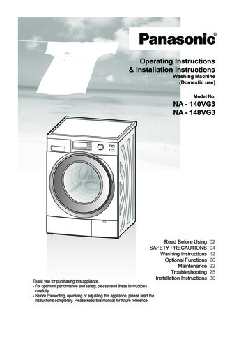
FORM 5S1375MODELS 1P899A THRU 1P903A, 2P432, 2P433 & 2P60901782Figure 5 — Replacement Parts IllustrationIReplacement Parts List00IREF,NO, 1DESCRIPTIONPump bodyFlange1P899A805482-0116X484 (3/4")6X485 0116X492(V)6X493 (1 VA"6X494(11/2"1P901A816327-011805210-011PART NUMBER FOR 116X488 (3/4")2A639(1")6X485(1")6X489 1")2A640(iy4")6X490 11/4")2A641(1%")6X491(11/ ") ,816653-00()804034-000805176-000Flange gasket (rubber)804034-000805209-001Flange bolt17/16-14x1%"& nut11/2-13 ted motor assembly817025-001Pump body3/8-18 x 7/8"*capscrew7/16-14 x 1"Motor .11/4-20x5/8"capscrew15/16-18 x 3/4"**"tlmpeller assembly1R2411R2491R2471R2481R2471R470(pump repair kit)1R2711R2711R2711R2711R2719 Coupler 001816706-001A816706-002Seal 000A106050-000Pump body gasket* Standard hardware item, available localtKit comes assembled and includes impeller, seal, shaft & bearing module, bracket, gasket,A Not illustrated.NOTE: Motor bracket not available separately; part of motor.2P433805484-011805189 0112P609811240-0416X 4721R462816706-001806050-000coupler & tube of oil1R463816706-002106050-000
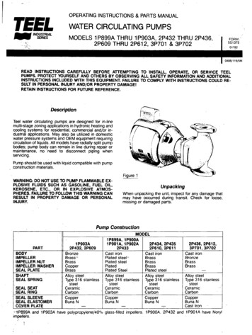
FORM 5S1375MODELS 2P434 THRU 2P436, 2P610 THRU 2P612, 3P701 & 3P70201782ORDER REPUCEMENT RARTSBY CALUNG TOLL FREE1-800-323-0620 (Outside Illinois)1-800-225-7149 (Inside Illinois)Please provide the foQowing inlormation: Model Numtjer Serial Numlw (if any) Parts Description and Numberas shown in Parts ListAddress parts conespondence to:Dayton Electnc Mfg. Co.1250 Busch ParkwayBuffalo Grove. IL 60015IFigure 6 — Replacement Parts IllustrationReplacement Parts ListREF.NO.12345678910DESCRIPTIONPump bodyFlangeFlange gasket (rubber)Flange bolt(7/16-14x1%"&nut11/2-13x21/4"Mounted motor pscrew*PART NUMBER FOR 6707-001106592-000*[ . - Q JIQ.Motor capscrew 3/8-16 x 3/4"Impeller"teearing assemblyCoupler assemblySeal kitAPump body gasketA Standard hardware item, available locally,ANot illustrated.tBearing assembly includes seal, shaft and bearingsNOTE: Motor bracket not available separately; part 0471R4671R465816706-001806158-000gasket and tube of 0471R4671R465816706-001106158-000 *:874058-0511R4691R466816707-001106592-000
FORM 5S137501782MODELS 1P899A THRU 1P903A, 2P432 THRU 2P436, 2P609 THRU 2P612, 3P701 & 3P702Troubleshooting ChartSYMPTOMSNo liquid delivered.POSSIBLE CAUSE(S)1. Pump not prinied.CORRECTIVE ACTION1. Prime pump.2. Speed too low.3. Air leak in suction.2. Check voltage.4. Discharge head too high.3. Repair or replace.4. Lower the height.5. Suction lift too high.5. Lower the height.6. Impeller plugged.7. Wrong direction of rotation.6. Clean out7. Change direction.8. Coupler broken because of pump and 8. Motor rubber resilient rings sagged,motor shaft misalignment.replace motor.9. Coupler broken because of pump9. Replace impeller assemblybearing being wom and assemblywobbling.Not enough liquid delivered.1. Air leaks in suction.1. Repair or replace.2. Speed too low.2. Check voltage.3. Lower the height.3. Discharge head too high.4. Suction lift too high.4. Lower the height5. Impeller partially plugged.5. Clean out.6. Not enough suction head for hot liquid.7. Impeller or casing damaged.6. Increase suction head.8. Suction not submerged enough.Not enough pressure.1. Speed too low.2. Air or gas in liquid or leaks in suction.7. Replace.8. Submerge suction.1. Check voltage.2. Repair or replace suction line.3. Impeller damaged or partially plugged. 3. Clean or replace.4. Pumped liquid has too much solid4. Add strainer.material mixed with it.Pump works for awhilethen loses suction.Motor trips overload.Seal leaks.1. Leaky suction line.1. Repair or replace.2. Suction lift too high.3. End of suction line uncovered.4. Air leaks in suction.2. Lower the height.3. Submerge end of suction line.4. Repair or replace suction line.1. Seal binding.2. Rotor binding.1. Replace.2. Rep
operating instructions & parts manual water circulating pumps models 1p899a thru 1p903a, 2p432 thru 2p436, 2p609 thru 2p612, 3p701 & 3p702 form 5s1375 01782 0488/119/5m read instructions carefully before attempting to install, operate, or service teel pumps. protect yourself and others by observing all safety information and additional