Transcription
This .pdf document is bookmarkedOperating Instructions and Parts ManualVariable Speed Vertical MillModel JTM-1055JET427 New Sanford RoadLaVergne, Tennessee 37086Ph.: 800-274-6848www.jettools.comPart No. M-690055Revision D1 11/2017Copyright 2017 JET
1.0 Warranty and ServiceJET warrants every product it sells against manufacturers’ defects. If one of our tools needs service or repair, pleasecontact Technical Service by calling 1-800-274-6846, 8AM to 5PM CST, Monday through Friday.Warranty PeriodThe general warranty lasts for the time period specified in the literature included with your product or on the officialJET branded website. JET products carry a limited warranty which varies in duration based upon the product. (See chart below) Accessories carry a limited warranty of one year from the date of receipt. Consumable items are defined as expendable parts or accessories expected to become inoperable within areasonable amount of use and are covered by a 90 day limited warranty against manufacturer’s defects.Who is CoveredThis warranty covers only the initial purchaser of the product from the date of delivery.What is CoveredThis warranty covers any defects in workmanship or materials subject to the limitations stated below. This warrantydoes not cover failures due directly or indirectly to misuse, abuse, negligence or accidents, normal wear-and-tear,improper repair, alterations or lack of maintenance. JET woodworking machinery is designed to be used with Wood.Use of these machines in the processing of metal, plastics, or other materials outside recommended guidelines mayvoid the warranty. The exceptions are acrylics and other natural items that are made specifically for wood turning.Warranty LimitationsWoodworking products with a Five Year Warranty that are used for commercial or industrial purposes default to aTwo Year Warranty. Please contact Technical Service at 1-800-274-6846 for further clarification.How to Get Technical SupportPlease contact Technical Service by calling 1-800-274-6846. Please note that you will be asked to provide proofof initial purchase when calling. If a product requires further inspection, the Technical Service representative willexplain and assist with any additional action needed. JET has Authorized Service Centers located throughout theUnited States. For the name of an Authorized Service Center in your area call 1-800-274-6846 or use the ServiceCenter Locator on the JET website.More InformationJET is constantly adding new products. For complete, up-to-date product information, check with your local distributoror visit the JET website.How State Law AppliesThis warranty gives you specific legal rights, subject to applicable state law.Limitations on This WarrantyJET LIMITS ALL IMPLIED WARRANTIES TO THE PERIOD OF THE LIMITED WARRANTY FOR EACH PRODUCT.EXCEPT AS STATED HEREIN, ANY IMPLIED WARRANTIES OF MERCHANTABILITY AND FITNESS FOR APARTICULAR PURPOSE ARE EXCLUDED. SOME STATES DO NOT ALLOW LIMITATIONS ON HOW LONG ANIMPLIED WARRANTY LASTS, SO THE ABOVE LIMITATION MAY NOT APPLY TO YOU.JET SHALL IN NO EVENT BE LIABLE FOR DEATH, INJURIES TO PERSONS OR PROPERTY, OR FORINCIDENTAL, CONTINGENT, SPECIAL, OR CONSEQUENTIAL DAMAGES ARISING FROM THE USE OF OURPRODUCTS. SOME STATES DO NOT ALLOW THE EXCLUSION OR LIMITATION OF INCIDENTAL ORCONSEQUENTIAL DAMAGES, SO THE ABOVE LIMITATION OR EXCLUSION MAY NOT APPLY TO YOU.JET sells through distributors only. The specifications listed in JET printed materials and on official JET website aregiven as general information and are not binding. JET reserves the right to effect at any time, without prior notice,those alterations to parts, fittings, and accessory equipment which they may deem necessary for any reasonwhatsoever. JET branded products are not sold in Canada by JPW Industries, Inc.Product Listing with Warranty Period90 Days – Parts; Consumable items1 Year – Motors; Machine Accessories2 Year – Metalworking Machinery; Electric Hoists, Electric Hoist Accessories; Woodworking Machinery usedfor industrial or commercial purposes5 Year – Woodworking MachineryLimited Lifetime – JET Parallel clamps; VOLT Series Electric Hoists; Manual Hoists; Manual HoistAccessories; Shop Tools; Warehouse & Dock products; Hand Tools; Air ToolsNOTE: JET is a division of JPW Industries, Inc. References in this document to JET also apply to JPW Industries,Inc., or any of its successors in interest to the JET brand.2
2.0 Table of contentsSectionPage1.0 Warranty and Service . 22.0 Table of contents . 33.0 Safety warnings . 44.0 About this manual . 55.0 Specifications . 66.0 JTM-1055 Layout . 77.0 Setup and assembly . 87.1 Shipping container contents . 87.2 Unpacking and cleanup . 87.3 Site Preparation. 87.4 Lifting the Mill . 87.5 Electrical Connections . 97.6 Lubrication . 98.0 Controls . 99.0 Operating Precautions . 1110.0 Adjustments . 1110.1 Changing Speed Range . 1110.2 Manual Fine Feed (handwheel) . 1110.3 Manual Rapid Feed (handle) . 1210.4 Micro Adjusting Nuts for Manual Feed . 1210.5 Setting Up for Automatic Feed . 1210.6 Micro Adjusting Nuts for Auto Feed . 1210.7 Head Alignment . 1210.8 Pivoting the Head . 1310.9 Pivot the Ram . 1310.10 Moving the Ram . 1310.11 Table Movement . 1310.12 Feed Trip Adjustment . 1311.0 Maintenance . 1411.1 Knee Gib Adjustment . 1411.2 Saddle Gib Adjustment . 1411.3 Table Gib Adjustment . 1411.4 Ram Wear Plate Adjustment . 1411.5 Removing the Motor . 1411.6 Timing Belt Replacement . 1411.7 Drive Belt Replacement. 1511.8 Brake Shoe Replacement . 1512.0 Replacement Parts . 1512.1.1 Variable Speed Head – Exploded View . 1612.1.2 Variable Speed Head – Parts List . 1712.2.1 Head Assembly – Exploded View . 2012.2.2 Head Assembly – Parts List . 2112.3.1 Base Assembly – Exploded View . 2412.3.2 Base Assembly – Parts List. 2512.4.1 Lead Screw Assembly – Exploded View . 2712.4.2 Lead Screw Assembly – Parts List . 2812.5.1 One Shot Lubrication System – Diagram . 2912.5.2 One Shot Lubrication System – Parts List. 3013.0 Electrical Connections . 3113.1 Forward/Reverse Switch Wiring . 3113.2 Wiring Diagram. 323
14. Make sure the mill is firmly secured beforeoperating.15. Make sure that workpiece is securely attachedor clamped to the table. Never use your handto hold the workpiece.3.0 Safety warnings16. Make all machine adjustments or maintenancewith the machine unplugged from the powersource.1.Read and understand the entire owner'smanual before attempting set-up or operationof this machine.2.Read and understand the warnings posted onthe machine and in this manual. Failure tocomply with all of these warnings may causeserious injury.3.Replace the warning labels if they becomeobscured or removed.18. Remove loose items and unnecessaryworkpieces from the area before starting themachine.4.This manual is intended to familiarize you withthe technical aspects of this milling machine.It is not, nor was it intended to be, a trainingmanual.19. Don't force a tool or attachment to do a job forwhich it was not designed. The right tool willdo the job better and more safely.5.This machine is designed and intended for useby properly trained and experienced personnelonly. If you are not familiar with the proper safeuse of milling machines, do not use thismachine until proper training and knowledgehas been obtained.6.7.17. Remove adjusting keys and wrenches. Form ahabit of checking to see that keys, wrenches,and other adjusting tools are removed frommachine before turning it on.20. Make certain the main switch is in the OFFposition before connecting the machine to thepower supply.21. Give your work undivided attention. Lookingaround, carrying on a conversation, and"horse-play" are careless acts that can result inserious injury.Do not use this mill for other than its intendeduse. If used for other purposes, JET, disclaimsany real or implied warranty and holds itselfharmless from any injury that may result fromthat use.22. Maintain a balanced stance at all times so thatyou do not fall or lean against moving parts.Do not overreach or use excessive force toperform any machine operation.23. Keep visitors a safe distance from the workarea. Keep children away.Always wear approved safety glasses/faceshields while using this machine. Note:Everyday eyeglasses only have impactresistant lenses; they are not safety glasses.8.Make certaingrounded.themachineis9.Before operating the machine, remove tie,rings, watches, other jewelry, and roll upsleeves above the elbows. Remove all looseclothing and confine long hair. Non-slipfootwear or anti-skid floor strips arerecommended. Do not wear gloves.24. Use recommended accessories;accessories may be hazardous.properlyimproper25. Keep hands away from all moving parts (belts,cutters, gears, etc.).26. Never operate this machine under theinfluence of alcohol, drugs, or any medicationwhich may impair your judgment.27. Some coolants used for machining containchemicals that may be hazardous to yourhealth if not used properly. Read andunderstand all user information listed on thecoolant container and protect yourselfaccordingly.10. Wear ear protectors (plugs or muffs) duringextended periods of operation.11. Keep the floor around the machine clean andfree of scrap material, oil and grease. Provideadequate space surrounding work area andnon-glare, overhead lighting.28. Turn off machine before cleaning. Use a brushor compressed air to removed chips anddebris – do not use your hands.12. Don’t use this mill in a dangerous environment,or damp or wet locations, or expose it to rain.29. Do not stand on machine; serious injury couldoccur if machine tips over.13. Keep machine guards in place at all timeswhen the machine is in use. If removed formaintenance purposes, use extreme cautionand replace the guards immediately uponcompletion of maintenance.30. Never leave the machine running unattended.Turn off power and do not leave the machineuntil it comes to a complete stop.4
31. CALIFORNIA PROPOSITION 65 WARNING:This product contains chemicals known to theState of California to cause cancer, or birthdefects or other reproductive harm.State of California to cause birth defects and,in some cases, cancer. (California Health andSafety Code Section 25249.5 et seq.)33. Failure to comply with all of these warningsmay cause serious injury.32. This product, when used for welding, cutting,or working with metal, produces fumes, gases,or dusts which contain chemicals known to theFamiliarize yourself with the following safety notices used in this manual:This means that if precautions are not heeded, it may result in minor injury and/or possiblemachine damage.This means that if precautions are not heeded, it may result in serious injury or possibly evendeath.4.0 About this manualThis manual is provided by JET covering the safe operation and maintenance procedures for a JET ModelJTM-1055 Mill. This manual contains instructions on installation, safety precautions, general operatingprocedures, maintenance instructions and parts breakdown. Your machine has been designed and constructedto provide consistent, long-term operation if used in accordance with the instructions set forth in this document.If there are questions or comments, please contact your local supplier or JET. JET can also be reached at ourweb site: www.jettools.com.Retain this manual for future reference. If the machine transfers ownership, the manual should accompany it.Read and understand the entire contents of this manual before attempting assemblyor operation! Failure to comply may cause serious injury!5
5.0 SpecificationsModel Number . JTM-1055Stock Number . 690055Spindle Taper . NST#40Diameter of Quill . 4 1/8"Number of Spindle Speeds . VariableRange of Spindle Speeds . 80 to 3800 RPMDownfeeds per Revolution of Spindle . 0.0015", 0.003", 0.006"Spindle Travel . 5"Head Movement . 90 L and RTurret Rotation .360 Maximum Distance Spindle to Table . 20"Maximum Distance Spindle to Column . 26"Collet Capacity . 1/8”-7/8”Table Size . 10" x 54"Longitudinal Table Travel . 32"Table Cross Travel . 16"Number of T-Slots . 3Size and Spacing of T-Slots .5/8" x 2-1/2"Maximum Table Load . 800 lbs.Knee Travel .17-1/2"Overarm Travel . 16-1/2”Overall Dimensions . 108"W x 80"D x 92"HMotor . 5 HP, 3Ph., 230/460V prewired 230 VoltNet Weight (approx.) . 3,300 Lbs.The specifications in this manual were current at time of publication, but because of our policy of continuousimprovement, JET, reserves the right to change specifications at any time and without prior notice, without incurringobligations.6
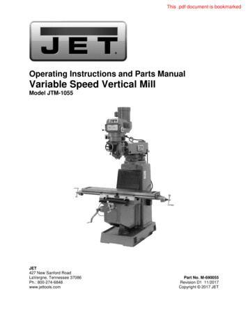
6.0 JTM-1055 Layout7
the head to raise into position. Do not removethe nuts; just break the nuts loose.7.0 Setup and assembly3.Turn the hex head of the worm shaft (B, Fig. 2)using a 19mm socket and breaker bar. Raisethe head aligning the zero marks on thescales. With the help of another personsupport the head while it is raising.4.Tighten the four bolts (A, Fig. 1).5.Loosen the two ram locking handles (C, Fig. 1)and move the ram forward by turning the hexhead of the ram pinion (D, Fig. 1) with a 19mmsocket and breaker bar.6.Tighten the ram locking handles before lifting.7.1 Shipping container contents1111111MillFlat Way Cover (rear)Accordion Way Cover (front)Elevating CrankQuill HandleDrawbarPin & Nut1ToolBox: found in base through rear cover1 Hex Wrench Set1 Wrench Set1 #2 Cross Point Screw Driver1 #2 Flat Blade Screw Driver1 Plastic Oil Can1 Owner’s Manual1 Warranty Card1 Eye Bolt3 Handles4 Leveling Bolts4 Leveling Pads7.2 Unpacking and cleanup1.Finish removing the crate. Leave the millbolted to the pallet until it is ready to be movedto its final location.2.Remove the toolbox from the base. It isaccessed by removing four screws that holdthe rear cover in place.3.Clean all rust protected surfaces withkerosene, or a light solvent. Do not usegasoline, paint thinner, or lacquer thinner.These will damage painted surfaces.4.Cover all machined surfaces with a film of lightmachine tool oil to inhibit rust.7.3 Site PreparationFigure 1The preferred method for lifting the mill is with ahook through the eye bolt in the ram (E, Fig. 1).Make sure the chain and hook are properly ratedfor the weight of the mill. Make sure the chain isnot twisted and lift slowly. Make sure the mill isbalanced before moving.Mill must be supported equallyunder all four corners. Failure to comply maycause the column to twist and put a bind in thebedways.The mill must be placed on an even surface, boltedto the floor, or placed on the leveling pads. Choosea location for the mill that is dry, has good lighting,and has enough room to be able to service the millon all four sides. Review the JTM-1055 Layout insection 6.0.Carefully move the mill over the site. Lower the millover the anchor bolts, or leveling pads. Theleveling pads included in the toolbox and theleveling screws will help you to reach a levelposition. Check the mill for level with a machinist'slevel placed on the table. Mill must be level back tofront and side to side. Shim if necessary whenbolting to the floor, but remember that the mill mustbe supported equally at all four corners. Check forlevel before tightening the anchor bolt nuts andafter tightening them. Adjust as necessary.7.4 Lifting the Mill1.Remove the four nuts that hold the unit to thepallet.2.Raise the head by loosening four nuts, (A, Fig.1) with a 22mm wrench, just enough to allow8
7.5 Electrical ConnectionsAll electrical connectionsmust be made by a qualified electrician. Failureto comply may cause serious or fatal injury.The JTM-1055 mill is rated at 230/460V, 3Ph andcomes from the factory prewired at 230V.Confirm power at the site matches powerrequirements of the mill before connecting to thepower source. The power source should bededicated to the JTM-1055 mill. The main powerswitch is located on the right side of the machine.Remove the cover, and run the main power cablethrough the box and attach the ground, followed bypower leads. Replace the cover.Check for proper spindle rotation in the high speedrange. The spindle should rotate clockwise whenviewed from the top of the machine. If the spindlerotates counter-clockwise, disconnect from thepower source, and switch two of the power leads.Figure 2To change from 230V to 460V operation, removethe junction box cover on the motor, and changethe wires according to the diagram found on theinside of the cover. Also see the wiring diagram atthe back of this manual.The mill must be properly grounded.7.6 LubricationDo not operate the mill beforelubricating the machine fully. Failure to complymay cause damage to the machine.1.Spindle Bearings & Quill (A, Fig. 2)- fill oil cupsonce daily with Mobil DTE Oil Light.2.Oil Pump (B, Fig. 2)- fill reservoir as needed byremoving cap on top of tank and filling withMobil DTE Oil Light. Pump oil with releasehandle daily. Way surfaces and leadscrewsare lubricated in this manner.3.Grease Fitting for Spindle Gear (not shown):located on the backside of the head’s lowerhousing. Lubricate every month using MobilithAW2.Figure 3B. Variable Speed Dial Indicator (B, Fig. 3) located on the front of the head assembly.Indicates selected speed in high or lowrange.8.0 ControlsA. Variable Speed Control (A, Fig. 3) located on the right side of the headassembly. Turn clockwise or counterclockwise to adjust spindle speed.C. Spindle Brake (C, Fig. 3) - located on leftside of the head. Move in either direction tostop spindle once power has been turnedoff.Change speed only whenspindle is turning.9
G. Quill Lock (G, Fig. 4) - located on the rightside of the head.Rotate the handleclockwise to lock the quill in a desiredposition.Rotate the handle counterclockwise to release.H. Micro Adjusting Nut (H, Fig. 4), - locatedon the front of the head. Use for settingspecific spindle depth. Note: One completerotation of the micro nut equals 0.05”.Figure 4D. High-Neutral-Low Lever (D, Fig. 4) located on the right side of the head. Thephoto shows the lever in the low speedrange. Push the lever in and rotate 90 clockwise for neutral. Rotate the leveranother 90 for the high speed range.CAUTION: Do not shift High-Low Gearwhile motor is running. Rotate the spindleby hand to facilitate changing leverpositions.Figure 5I.Feed Control Lever (I, Fig. 5) - located onthe left side of the head. Engages overloadclutch on pinion shaft when the lever ispositioned to the left. Stays engaged untilquill stop comes in contact with microadjusting nut (forcing feed control lever todrop out automatically), or until lever isreleased manually by positioning lever tothe right.J.Manual Feed (J, Fig. 5) - located on the leftfront of the head. Feed reversing knob (K,Fig. 5) must be in the neutral position. Thefeed control lever (I, Fig. 5) must beengaged. Note: manual feed handle andhandwheel may be taken off when not inuse.E. Power Feed Transmission EngagementKnob (E, Fig. 4) - located on right side ofhead. When pointer indicates towards therear of the machine, power feed worm gearis engaged. To disengage power feed, turnso pointer indicates towards the front of themachine.CAUTION: Power feed may be engagedwhen spindle is rotating, however, it must beengaged gently to avoid damage to theworm gear. Do not use power feed at speeds above2700 R.P.M. It is recommended that the power feedworm gear be disengaged whenever thepower feed is not required. This avoidsunnecessary wear on the worm gear. Maximum loading is a 3/8” (9.5mm)diameter bit for drilling in steel. Usemanual feed for bits larger than 3/8".F.K. Feed Reversing Knob (K, Fig. 5) - locatedin center of manual feed handwheel.Position of the knob depends upon thedirection of spindle rotation. If boring withright hand cutting tools, pull feed knobtowards operator until clutch becomesengaged.Neutral position is betweenforward and reverse position.Quill Feed Handle (F, Fig. 4) - located onright side of head. Rotate clockwise tolower spindle.10
CAUTION: It is recommended that the knobbe left in the neutral position when not inuse.L.is not required. This will avoid unnecessarywear on the worm gear.Quill Stop (L, Fig. 6) - located on the frontof head. Used to disengage the automaticfeed in either direction as well as the settingpoint for working to a given depth.M. Quill Feed Speed Selector (M, Fig. 6) located on the left side of the head. Turnthe knob and indicate pointer towards oneof three feed speeds (0.0015”, 0.003”, and0.006”) per spindle revolution. Feed is morereadily engaged when spindle is turning. Maximum loading is a 3/8” (9.5mm) diameterbit for drilling in steel. Use manual feed for bitslarger than 3/8". Overload clutch is factory set to hold up to 200lbs. down feed pressure on the quill(accommodates drills up to 3/8"). Do notatte
JTM-1055 Mill. This manual contains instructions on installation, safety precautions, general operating procedures, maintenance instructions and parts breakdown. Your machine has been designed and constructed to provide consistent, long-term operation if used in accordance with the instructions set forth in this document.