Transcription
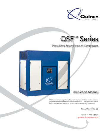
QSF SeriesDirect Drive Rotary Screw Air CompressorsInstruction ManualThis manual contains important safety information and should be made available toall personnel who operate and/or maintain this product. Carefully read this manualbefore attempting to operate or perform maintenance on this equipment.Manual No. 55002-CBOctober 1998 EditionUpdated: Septermber 2010
TABLE OF CONTENTSSection I – General InformationStandard Warranty. 1Safety Precautions and Warnings .2-4Section II - DescriptionGeneral Description of Quincy QSF Series Air Compressors. 5The Compression Cycle. 6Description of Air Flow . 6Description of Fluid Flow and Compressor Cooling System .6-7Modulation Control Standard. 7Auto/Dual Standard. 7Electrical System Description . 8Indicators . 9Section III - InstallationReceiving . 10Moving the Unit to the Installation Site. 10Location .10-11Piping Connections. 12Piping Fit-Up. 12Relief Valves. 12Pressure Vessels. 13Electrical . 13Guards . 13Manual Relief and Shutoff Valve. 14Water and Sewer Facilities at the Installation Site (Water-cooled models only) . 14Fluid Level. 15Compressor Rotation. 15Fan Rotation. 15Section IV – Operating ProceduresPrior To Starting. 16Starting the Compressor. 16Stopping the Compressor - Normal Operation . 17Stopping the Compressor - Emergency Operation . 17Electronic Control Operations.17-22Quincy Compressor – QSF Series
TABLE OF CONTENTS (continued)Section V - ServicingPreparing for Maintenance or Service . 23Safety . 23Lubrication . 24Fluid Specifications. 24Fluid Life . 24Water Removal . 25Understanding the Analysis Report .25-26Fluid Parameters . 27Fluid Filter. 28Compressor Air/ Fluid Separator Element . 29QGV-200 Separator Installation . 30Fluid Scavenging System. 31Air Filter . 32Control Line Air Filter . 32Compressor Shaft Fluid Seal . 33Preparation for New Seal Installation . 34Seal Installation. 34Air and Fluid Tubing . 35Section VI – Service AdjustmentsDifferential Pilot Valve . 36Water Temperature Regulating Valve . 36Water-cooled Heat Exchangers. 37Fluid Piping. 37Assembling SEAL-LOK Fittings . 38Section VII - TroubleshootingTroubleshooting .39-44Section VIII – Maintenance ScheduleMaintenance Schedule . 45Addendum 1 (Added 09/2010)Shell/Tube Heat Exchanger Installation and Service Recommendations.46Quincy Compressor – QSF Series
Section I – General InformationStandard WarrantyQuincy Compressor Industrial Rotary Screw ProductsQSF CompressorsSeller warrants products of its own manufacture against defects in workmanship and materials under normal useand service, as follows:Packaged Compressors - Twelve (12) months from date of start-up or eighteen (18) months from date ofshipment from the factory, whichever occurs first.Airend on Packaged Compressors (service at full load pressure 150 PSIG and below) - Twenty-four (24)months from date of start-up or thirty (30) months from date of shipment from the factory, whichever occurs first.Five (5) and ten (10) year Extended Airend Warranties are available. See pages 40-41 for details.Airend on Packaged Compressors (service at full-load pressure above 150 psig) - Twelve (12) months fromdate of start-up or eighteen (18) months from date of shipment from the factory, whichever occurs first.Remanufactured Airend - Twelve (12) months from date of shipment from factory.Parts - Ninety (90) days from date of Distributor sale or twelve (12) months from date of factory shipment,whichever occurs first.With respect to products not manufactured by Seller, Seller will, if practical, pass along the warranty of theoriginal manufacturer.Notice of the alleged defect must be given to Seller in writing with all identifying details including serial number,model number, type of equipment and date of purchase, within thirty (30) days of the discovery of same duringthe warranty period.Seller’s sole obligation on this warranty shall be, at its option, to repair, replace or refund the purchase price ofany product or part thereof which proves to be defective. If requested by Seller, such product or part thereofmust be promptly returned to Seller, freight collect for inspection.Seller warrants factory repaired or replaced parts of its own manufacture against defects in material andworkmanship under normal use and service for ninety (90) days or for the remainder of the warranty on theproduct being repaired, whichever is longer.This warranty shall not apply and Seller shall not be responsible or liable for:a)Consequential, collateral or special losses or damages;b)Equipment conditions caused by fair wear and tear, abnormal conditions of use, accident, neglect ormisuse of equipment, improper storage or damages resulting during shipment;c)Deviation from operating instructions, specifications, or other special terms of sales;d)Labor charges, loss or damage resulting from improper operation, maintenance or repairs made byperson(s) other than Seller or Seller’s authorized service station.e)Improper application of product.In no event shall Seller be liable for any claims, whether arising from breach of contract or warranty of claims ofnegligence or negligent manufacture, in excess of the purchase price.NOTICE!This warranty is the sole warranty of seller. Any other warranties, expressed or implied, including anywarranties of merchantability or fitness for a particular use are hereby excluded.Quincy Compressor – QSF Series1
Section I – General InformationSafety Cautions and WarningsListed are some, but not all, cautions that must be observed with compressors and compressed air systems.Failure to follow any of these warnings may result in death, serious injury, property damage and/or compressordamage.Air in the piping from this compressor will cause death or serious injury if used for breathing air. Additionally, airused in food processing or packaging requires the use of food grade fluid. Air used for these processes mustmeet OSHA 29 CFR 1910.134 regulations.This compressor is designed for use in the compression of normal atmospheric air only. No other gases, vaporsor fumes should be exposed to the compressor intake or processed through the compressor.Disconnect and lock out all power supplies to the compressor plus any remote controllers prior to servicing theunit.Relieve all pressure internal to the compressor prior to servicing. Do not depend on check valves to hold systempressure.A properly sized pressure relief valve must be installed in the discharge piping ahead (upstream) of any shut-offvalve (block valve), heat exchanger, orifice or any potential blockage point. Failure to install a relief valve couldresult in the rupturing or explosion of some compressor component.Do not change the pressure setting of the relief valve, restrict the function of the relief valve or replace the reliefvalve with a plug. Over pressurization of system or compressor component can occur, resulting in death, seriousinjury and property damage.Never use plastic pipe, rubber hose or soldered joints in any part of the compressed air system. Failure toensure system compatibility with compressor piping is dangerously unsound.Never use a flammable or toxic solvent for cleaning the air filter or any parts.Do not attempt to service any part while the compressor is operating.Do not operate the compressor at pressures in excess of its rating.Do not remove any guards or canopy panels while the compressor is operating.Observe gauges daily to ensure compressor is operating properly.Follow all maintenance procedures and check all safety devices on schedule.Never disconnect or tamper with the high air temperature (HAT) sensors.Compressed air is dangerous, do not play with it.Use the correct fluid at all times.Quincy Compressor – QSF Series2
Section I – General InformationNOTE:Read this manual and follow all instructions prior to installing or operating this compressor.These instructions, precautions and descriptions cover standard Quincy manufactured QSF series aircompressors.As a service to our customers, we often modify or construct packages to the customer’s specifications.This manual may not be appropriate in those cases.Every effort has been taken to ensure complete and correct instructions have been included in this manual,however, possible product updates and changes may have occurred since this printing. Quincy Compressorreserves the right to change specifications without incurring any obligation for equipment previously orsubsequently sold. Not responsible for typographical errors.Reference to the machine MODEL, SERIAL NUMBER and DATE OF ORIGINAL START-UP must be made inall communication relative to parts orders or warranty claim. A model/serial number plate is located on theframe and in the upper right corner inside of the control panel door.SPARE PARTS ORDERING -- Quincy Compressor maintains replacement parts for Quincy compressors. A partsmanual is shipped with all new machines. Order parts from your Authorized Quincy distributor. Use onlygenuine Quincy replacement parts. Failure to use genuine Quincy parts may void your warranty.! DANGER !Air from this compressor will cause death or serious injury if used forbreathing or food processing (if non-food grade fluid is used). Air used forthese processes must meet OSHA 29CFR1910.134 regulations orFDA21CFR178.3570 regulations.Quincy Compressor – QSF Series3
Section I – General InformationIMPORTANTThroughout this manual we have identified key hazards. The following safety alert symbols identify the level ofthe hazard.! DANGER !Hazards or unsafe practices that will result in death or serious injury.! WARNING !Immediate hazards which could result in death or serious injury.! CAUTION !Hazards or unsafe practices which may result in minor injury or product orproperty damage.Quincy Compressor – QSF Series4
Section II – DescriptionGeneral Description of Quincy QSF Series Air CompressorsThe compressor is a single stage, positive displacement, fluid-flooded helical screw type unit. Thecompressor consists of two precision-machined rotors. The male rotor is driven by a gear train,connected to motor shaft through a flexible drop out type coupling. The male rotor has four lobes thatmesh with a female rotor consisting of six flutes. Both rotors are housed in a single cast iron cylinder.The unit has an inlet port at the power-input end and a discharge port at the opposite end.All models use positive pressure in the reservoir to circulate fluid through the system.All components are attached to a heavy-duty steel frame. Controls and indicators are arranged on acontrol panel. Acoustical cabinets are available to reduce sound levels.Figure 2-1Quincy Compressor – QSF Series5
Section II – DescriptionThe Compression CycleThe compression cycle of a rotary compressor is a continuous process from intake to discharge with noreciprocating mechanisms starting and stopping as found in reciprocating compressors. The compressorconsists of two rotors in constant mesh, housed in a cylinder with two parallel adjoining bores. The maledrive rotor has four lobes that mesh with six flutes in the female rotor. All parts are machined to exactingtolerances.As the rotors rotate, (male-clockwise as viewed from the power-input end) air is drawn into the cylinderthrough the inlet port located at the power-input end. A volume of air is trapped as the rotor lobes passthe inlet cut off points in the cylinders. Compression occurs as the male rotor rolls into the female flute,progressively reducing the space thereby raising the pressure. Compression continues until the lobeand flute pass the discharge port. The compressed air is then discharged into the service line. There arefour complete compression cycles for each complete rotation of the male rotor. (Figure 2-1).Description of Air FlowWith the compressor operating, air entering via the compressor air filter flows directly into the rotorhousing where it is compressed. Compressed air passes through the complete system then through aminimum pressure check valve to the service connection.Description of Fluid Flow and Compressor Cooling SystemThe fluid serves three functions: it lubricates the bearings, rotors, and gears; it removes heat from the airas the air is being compressed thus lowering the compressed air discharge temperature; it also seals therotor clearances.CoolersAll models use positive pressure in the reservoir to circulate fluid. Fluid is circulated through the cooler,fluid filter, and into the compressor. In the compressor, some fluid is diverted directly through internalpassages to ensure positive lubrication of the bearings, gears and shaft seal. The remainder of the fluidis injected into the early stage of the compression cycle to seal clearances, cool, and lubricate the rotors.Fluid CoolersFluid coolers may use either air or water as a cooling medium. The following descriptions point out themajor differences between the two types of coolers.Air-cooled Fluid CoolersThe air-cooled fluid cooler and aftercooler are of the finned aluminum tube design. Ambient air isforced through the fins by a motor driven fan, cooling the fluid and air in the tubes. To maintain propercompressor operation, the temperature of the ambient air should not exceed the temperatures listed inthe QSF specifications. The cooler fins must be kept clean at all times. Fluid leaving the receiver passesthrough a thermal mixing valve before traveling on to the cooler. The purpose of the thermal valve is tomaintain a minimum fluid discharge temperature at the compressor of approximately 1800 Fahrenheit.Quincy Compressor – QSF Series6
Section II – DescriptionWater-cooled Fluid CoolersWater-cooled fluid coolers are of the shell and tube design. Fluid passes through the shell transferringits heat to the water flowing through the tubes. Fluid leaving the cooler does not pass through athermal mixing valve as in an air-cooled unit, but goes directly to the fluid filter and the compressor.Fluid discharge temperature at the compressor is maintained by a water temperature regulating valvelocated in the discharge water line. The water temperature-regulating valve uses a probe to sense fluidtemperature and opens and closes, governing water flow through the cooler.AftercoolersAir-cooled aftercoolers are furnished as standard equipment on the QSF. Water-cooled aftercoolers areavailable as an option on standard QSF. Aftercoolers are used to lower the temperature of thedischarge air, thereby condensing water vapor from the compressed air. This allows most of thecontained water to be trapped and expelled from the unit, reducing water related problemsdownstream.Air-cooled aftercoolers are part of the air-cooled fluid cooler. Cooling air from the fan is blown throughthe aftercooler and the fluid cooler.Water-cooled aftercoolers are placed in series with the fluid cooler. Incoming water is first directedthrough the aftercooler and then on to the fluid cooler.A combination moisture separator and water trap is provided for collecting and expelling water to thecustomer's drain.Modulation Control StandardAs the motor starts driving the compressor rotors, air is drawn in, compressed and discharged into thereservoir. When the air pressure in the reservoir exceeds the set point of the pilot valve (normally 100PSIG), the valve opens and passes a controlled volume of air to the inlet valve air cylinder. The air forcesa piston to move within the cylinder, closing the inlet valve. The compressor will continue to runmatching air demand with air delivery by constantly adjusting the position of the inlet valve. The inletvalve regulates compressor capacity between 100% and nearly 0% of rated delivery. When maximumpressure (typically 10 PSIG above normal full load pressure) has been obtained in the air system,complete compressor unloading occurs. The pressure transducer located in the control panel sends asignal to the control and the solenoid valve opens, venting the residual pressure from the blowdownvalve. At the same time, control air from the reservoir check valve is directed through the solenoid tothe inlet valve air cylinder.The inlet valve is held in a closed position, preventing the intake of air into the compressor and servingas a check valve preventing reverse air/fluid flow through the inlet valve and air filter. See controlschematic in parts manual.Auto/Dual StandardThe Auto/Dual system is standard on the Quincy QSF Compressor.The control uses a programmable timer to shut the compressor down if it stays unloaded for theprogrammed time period. The timer should be set during unit start up for a minimum of six (6) minutes.During the unloaded/timing mode, if plant pressure should drop causing the electronic control to loadthe compressor, the timer will reset.Quincy Compressor – QSF Series7
Section II – Description! WARNING !Never assume it is safe to work on the unit because it is not operating. Itmay be in the automatic stand-by mode and may restart at any time.Follow all safety instructions in the “Preparing for Maintenance” or“Service” chapters.Electrical System DescriptionA diagram of the electrical system is shown in the parts manual sent with the compressor. A wiringdiagram is also included in the control panel on all Quincy QSF compressors.NOTE:Due to continuing product improvements and updates, it is suggested that the wiring diagramincluded in the control panel be used when servicing the electrical control.NOTE:Standard drive motors are open drip proof 1800 RPM with a maximum ambient temperature ratingof 1040F. They are not suitable for salt laden, corrosive, dirty, wet or explosive environments.The QSF series compressors utilize 460V incoming power through a magnetic motor starter. Atransformer in the control panel reduces this voltage to 120 VAC for the various controls on the unit,which is then reduced to 24 volt for the electronic controls. These controls include the pressuretransducer, high air temperature switch and probe, solenoid valve and the various indicator lights. Otherincoming line voltages are available as options. The compressor is provided with a NEMA 1 enclosure.Optional panels include NEMA 4.Air-cooled models utilize a second magnetic starter for the fluid cooler fan motor. If the fan motorstarter overload trips out for any reason, the compressor unit will shut down.! WARNING !High voltage could cause death or serious injury. Disconnect all powersupplies before opening the electrical enclosure or servicing.Safety SensorsTwo high air temperature (HAT) sensors are standard on the QSF units. These sensors protect the unitby sensing unusually high temperatures and shutting the unit down. One is located in the discharge linefrom the compressor. The second sensor is located at the minimum pressure check valve. These nonadjustable sensors are set to trip at approximately 2250F.Quincy Compressor – QSF Series8
Section II – Description! WARNING !Never remove, bypass or tamper with this HAT switch. Failure to providethis safety feature could cause death, serious injury and/or propertydamage. If the compressor is shutting down due to high dischargetemperature, contact a qualified service technician immediately.IndicatorsMain Power Light OnIndicates power from the main disconnect switch has been turned on and there is live power at thecompressor starter and control panel. This light will remain on as long as there is power to the unit.! CAUTION !Always check power supply disconnect. The Power-on light may beinoperable.High Discharge Air Temperature LightIndicates the unit has sensed an unusually high discharge temperature.Motor Overload FaultIndicates excessive over amp of drive motor and fan motor if air-cooled.Fluid Filter Change LightThis is used to determine fluid filter change intervals on the QSF, as programmed by the operator. Italso indicates excessive pressure differential across the fluid filter on the standard QSF.Air/Fluid Separator Element Change LightThis is used to determine separator element change intervals on the QSF, as programmed by theoperator. It also indicates excessive pressure differential across the air/fluid separator element on thestandard QSF.Air Intake Filter Change LightThis indicator signals when the filter element needs to be cleaned or replaced on the QSF.NOTE:Both the standard and stock versions include a programmable change interval timer on the air filter, fluidfilter and the air/fluid separator element.Quincy Compressor – QSF Series9
Section III – InstallationReceivingUpon receipt of the compressor, immediately inspect the compressor for any visible damage which mayhave occurred in shipment. If visible damage is found at the time of delivery, be sure the deliveringcarrier makes a notation on the freight bill and request a damage report. If the shipment is acceptedand it is later found that the compressor unit has been damaged, this is classified as concealed damage.If concealed damage is found, report it within 15 days of delivery to the delivering carrier, who mustprepare a damage report. Itemized supporting papers are essential to filing a claim.Read the compressor nameplate to be sure the compressor is the model and size ordered and thatoptionally ordered items are included.Check the reservoir and pressure relief valves to be sure they are adequate for the pressure at which youintend to operate.Moving the Unit to the Installation SiteWhen a forklift is used to move the unit to its installation site, use forklift slots provided in one side andone end of the main frame. Use of chains and slings should be limited to the main frame. Do notattempt to lift the unit by attachment to any components. Optional lifting eyes are available.NOTE:See technical data pages for detailed technical information and dimensions.! CAUTION !Improper lifting can result in component of system damage or personalinjury. Follow good shop practices and safety procedures when moving theunit.LocationLocate the compressor on a level surface that is clean, well lit and well ventilated. Allow sufficient space(four feet of clearance on all sides and top of the compressor) for safe and proper daily inspection andmaintenance. The entire length of the frame base must be supported. Shim where necessary but donot use wood. Ambient temperature should not exceed 1100 F. (Failure to heed this may result in ahigh air temperature shutdown.) Careful consideration of room size and shape must be done so that hotexhaust air from the cooling fan does not recirculate within the room, causing the operatingtemperatures to rise. High temperature shutdown may result. All models are intended for indoorinstallation; however, it is possible, with certain modifications, to accommodate some outdoor locations.Cabinet models are water-resistant but not water tight. Sheltering from rain, snow and freezingtemperatures is mandatory.Quincy Compressor – QSF Series10
Sectio
SPARE PARTS ORDERING -- Quincy Compressor maintains replacement parts for Quincy compressors. A parts manual is shipped with all new machines. Order parts from your Authorized Quincy distributor. Use only genuine Quincy replacement parts. Failure to use genuine Quincy parts may void your warranty. ! DANGER !
