Transcription
AC 2010-1026: DATA ACQUISITION IN A VEHICLE INSTRUMENTATIONCOURSEDavid McDonald, Lake Superior State UniversityDavid McDonald is a Professor of Electrical Engineering at Lake Superior State University andthe ASEE Campus Representative. He also does consulting in the area of test cell developmentfor electric vehicle engineering.Page 15.341.1 American Society for Engineering Education, 2010
Data Acquisition Applications in a Vehicle Instrumentation CourseAbstractThe paper introduces instrumentation and data acquisition instruction in a course on vehicleinstrumentation. The goal is to build students’ skill set with the technology while nurturing theirskills and confidence in the design and implementation of testing processes and procedures.Data acquisition instruction focuses on applications of MATLAB/Simulink, LabVIEW, andController Area Network (CAN) hardware and software. The instructional activities introducetypical industrial applications such as the concept of bench marking while engaging the studentsin the design of the testing process. It also introduces students to modeling and model validationwhen evaluating the acquired data from the device under test.The specific course, EGEE365 Vehicle Instrumentation, was piloted twice as a special topicsclass, and is now a regular offering within a new Vehicle Systems Option in the ElectricalEngineering and Mechanical Engineering Plans of Study. An overview of the course and it’splacement within a vehicle system option in electrical and mechanical engineering is outlined asa context for the data acquisition and control laboratory activities. Course instruction presentsvehicle data acquisition applications while including discussions on the operation and testing of ageneric electric vehicle drive train. An internal combustion vehicle and a vehicle chassisdynamometer are also used in the laboratory experience.A sample laboratory project and assessment discussion is presented. An assessment datasummary is also provided for the previous offering of the course along with the larger setting ofengineering professionalism data in electrical and mechanical engineering.IntroductionPage 15.341.2The application of modern instrumentation is important in engineering education to providestudents with critical skills for use in research and industry. Providing interesting andmotivational learning opportunities in engineering laboratory experiences builds students’enthusiasm while teaching critical skills in modern instrumentation and engineering problemsolving. It is relatively easy to provide students with interesting instrumentation activities todayby using low cost data acquisition hardware and software, and to explore interesting dataacquisition applications while implementing group, project-based instruction. Vehicleinstrumentation applications today embrace a large spectrum of applications with the increasedemphasis on CAN communications and emerging areas such as the growth in electric vehicledevelopment and vehicle-to-vehicle communications. This technology provides an avenue toteach core concepts and techniques of data acquisition while focusing on modern applicationswithin vehicle engineering including electric vehicle applications.
Instruction ApproachProject-based learning is effective in improving learning outcomes and increasing students’retention for courses and programs. The use of projects in both lower and upper level coursescan increase students’ interest and success provided the level of difficulty of the project matchesthe students’ skill level. Active discovery and engineering problem solving techniques, includingprojects and laboratory experiences, have been shown to increase learning success for the courseobjectives. Duesing et al1. Spinelli, et al2, reports that the development of a discovery basedsystem laboratory using LabVIEW and MATLAB empowered students to ‘discover’ someproperties in the laboratory before they were discussed in the lecture which can lead to a greaterappreciation of the material. Frank, et al3 indicated that keeping students engaged through ateaching studio, software, and class discussions was preferable to lectures.Providing students with more open-endedness in their learning experiences causes them tobecome more actively engaged and to exhibit a higher level of satisfaction with the course asindicated by Pape4. Casey et al5 reported that, while project work was always seen as an integralpart of later semesters in the curriculum, the need became evident to apply project-based learning(PBL) earlier, primarily to motivate early-stage students that otherwise failed to recognize theapplicability of what they were studying to their future professions.Electric Vehicle InstructionThere is tremendous interest in electric vehicles today. Several major automotive manufacturersare developing an electric car for mass production, and the United States is on the eve of massproducing an electric car for the first time in history. US Economic Stimulus funding and similaractivities are encouraging and fostering new technical development, and the engineeringeducation community needs to evaluate its role in this process6.There are many recently documented examples of electric vehicle applications withinengineering education. Three course experiences on instrumentation, electric vehicles andproject activities were reported by Rizkalla et al7,8,9. A summary of the outcomes from thesethree experiences are that the students were very satisfied, learned technical content not coveredin other courses, and felt that the course helped prepare them for the real world of engineering.From an instructor viewpoint the course(s) relied heavily on industrial cooperation, and includedhands-on experiences. The authors also noted that an industrial-based course in a new technicalarea may require heavy industrial collaboration.Page 15.341.3Two interesting LabVIEW-based electric vehicle projects that were reported include thedevelopment of a Virtual Hybrid Electric Vehicle Simulator using LabVIEW (Laio et al10), andanother project, reported by Winstead, et al11, to convert a stock Toyota Prius to a plug-in hybridhaving enhanced electric only range capability. The project used National InstrumentsLabVIEW software and hardware. One assessment outcome was that the project benefited byhaving both EE and EET students on the team. Parten, et al12 reported on a project to convert aGM Equinox into an alternative fueled, hybrid electric vehicle. The project outcomes indicated
that allowing students to participate in project-based helped students in the areas of interfacing,decision making and cooperation.Efforts by Macomb Community College and Wayne State University include an ATE-NSFproject Hybrid Electric Vehicle (HEV) curriculum to develop specialized HEV courses asreported by Yet et al13. Additional joint activities as reported by Rathod et al14 includes coursesin Energy Sources and Conversion, Control Systems for Vehicles, Fuel Cell Technology, HybridVehicle Technology, Applied Vehicle Dynamics and Advanced Manufacturing Processes.The US Government has been proactive in supporting new energy related curriculum and coursedevelopment. One example is a joint effort by the University of Michigan and General Motorsto create a program and laboratory to educate automotive battery engineers15, 16. Another aspectof the government funding includes a joint program involving several Indiana based universitiesto educate and train the work force needed to design, manufacture and maintain advancedelectric vehicles and the associated infrastructure.17Using project-based instruction in modern data acquisition and instrumentation tools andprocesses helps prepare students for today’s engineering challenges. Several authors havereported positive experiences from initiating an electric vehicle course or focused project, andmany new courses are in the midst of the development process. It is hopeful that project-basedlearning experiences in the context of electric vehicle development will help to draw out ofstudents a realization that they can make a meaningful contribution to something bigger thanthemselves.SettingThe School of Engineering, Technology and Development degree program offerings includeEAC/ABET accredited programs in computer, electrical and mechanical engineering and aTAC/ABET accredited program in Manufacturing Engineering Technology. The interest indeveloping offerings in the vehicle systems area while maximizing the use of resources byoffering courses to multiple majors led to the development of new Vehicle Systems Options forelectrical and mechanical engineering18,19.The Degree Plans of Study for both Electrical Engineering and Mechanical Engineering havedesignated options (concentrations) in which students take a prescribed cluster of courses. Theirfinal diploma then designates both the engineering major and the option specialty. ElectricalEngineering students can select from a prescribed set of courses that comprise a Digital,Robotics, Mechanical, Vehicle Systems or General Option. All five options require 11 credits.The Vehicle Systems Option is outlined below in Figure 1: Electrical Engineering VehicleSystems Option. Electrical Engineering majors are not required to take dynamics as part of theircore graduation requirements, but it is required for the Vehicle Systems Option.Page 15.341.4
Electrical Engineering Vehicle Systems OptionCourseNumberCourse TitleLaboratoryExperienceCreditsEGEM 320Dynamics3EGME 310Vehicle Development & Testing2EGEE 365Vehicle Instrumentation4NoneSoftware (50%)& Hardware (50%)Software (50%)& Hardware (50%)EGME 415Vehicle Dynamics2NoneFigure 1: Electrical Engineering Vehicle Systems OptionThe Vehicle Systems Option for Mechanical Engineering students is outlined below in Figure 2:Mechanical Engineering Vehicle Systems Option. Mechanical Engineering majors who selectthe Vehicle Systems Option also take EGEE280 Introductory Signal Processing course forelective credits.Mechanical Engineering Vehicle Systems OptionCourseNumberCourse TitleCreditsEGME 240Assembly Modeling and GD&T3EGME 310Vehicle Development & Testing2EGEE 365Vehicle Instrumentation4EGME 415Vehicle Dynamics2EGME 425Vibrations & Noise Control4LaboratoryExperienceSoftware (100%)Software (50%)& Hardware (50%)Software (50%)& Hardware (50%)NoneSoftware (25%)& Hardware (75%)Figure 2: Mechanical Engineering Vehicle Systems OptionThis new option includes three, new specialized courses that place a high value on laboratoryinstruction. The three courses are 1) EGME310 Vehicle development & Testing, 2) EGEE365Vehicle Instrumentation, and 3) EGME415 Vehicle Dynamics. In addition, some students whohave selected a different option will also take one or more of the courses either because of apersonal interest or to enhance their engineering skill set in preparation for industry.Vehicle Instrumentation CoursePage 15.341.5The EGEE365 Vehicle Instrumentation course introduces instrumentation hardware and softwarethat support the development, operation, and testing of vehicle systems. The course has evolvedthrough two offerings of a special topics course, and is now a designated electrical engineeringcourse. General topics include vehicle networks, data acquisition and control systems, modelingand simulation, and hardware and sensor interfacing.
The prerequisite courses are EGEE210 Circuit Analysis (DC & AC Circuits), and EGNE265 CProgramming. A two credit course, EGNR140 Numerical Analysis (with MATLAB) is aprerequisite for the C programming course. The students are usually juniors or seniors, and havealso completed a course on numerical analysis applications using MATLAB. The electricalcircuit analysis course provides students with an electrical background to wire circuits and usetest equipment. The C programming background helps prepare students for learning the CANsoftware which uses C syntax. The programming background also enables covering LabVIEWtopics, such as data types and arrays, relatively quickly because students have previousexperience with these items.The course is structured as three, 50-minute classes and a three-hour lab each week. The classesmay follow a lecture format to explain new material, but many classes tend to be of a discussionformat. Initial laboratory instruction is taught in a traditional electronics laboratory withcomputers on each student work bench, and a chassis vehicle dynamometer is used for someexercises later in the course. In addition to scheduled laboratory times, students may have afterhours access to the lab with the instructor’s permission.Instructional resources include the book LabVIEW for Everyone 3rd Edition by Jeffrey Travisand Jim Kring (ISBN 0-13-185672-3), and the Programming With CAPL manual for CANoe20.The CAPL manual is downloaded from the Vector CANtech website, and reprinted on campuswith written permission. An appendix in the CAPL manual is used for instruction on the CANbus operation. Other handouts and laboratory exercises are instructor generated based onacademic and industrial experience.Graded items include homework, quizzes, exams, laboratory exercises, and projectdocumentation. Students are required to maintain an engineering notebook with an industrialformat flavor. Students write formal, business-style memos on major projects in theOrganizational Purpose (OP), Technical Task (TT), and Rhetorical Purpose (RP) format. Thewriting also includes journals with both free-write and assigned topics. Finally, there are somewritten User Manuals and Testing Procedure assignments to give students an opportunity toexperience that type of writing.Real-World TopicsThe vehicle instrumentation course provides students with a general data acquisition and analysisfoundation that will serve the student in future study and in industry. The acquisition andanalysis of component data is important because data is required throughout the life expectancyof a product. Test data is essential in the design and validation process, performance evaluation,durability testing, production end-of-line testing, and in-service use of the product. Data can beobtained directly from sensors attached to the device, or, in the case of vehicles, it may beavailable from existing in-vehicle networks. Therefore, data acquisition from in-vehiclenetworks is also introduced in the course.Page 15.341.6
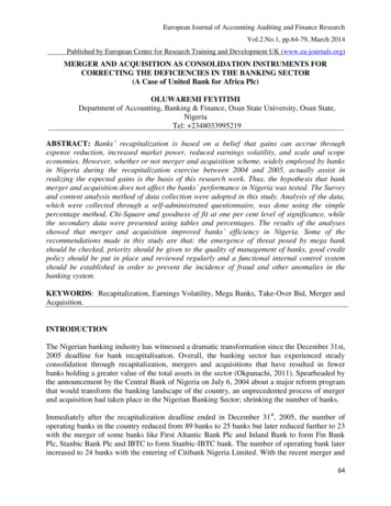
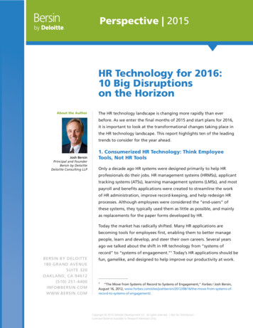
While many students who are interested in vehicle applications have some background ininternal combustion engine vehicles, few students have had any exposure to electric vehicleapplications so this area is also introduced in the course.General Data Acquisition TopicsGeneral hardware topics include an overview of sensors, connection methods (single vsdifferential inputs), ranging, offsets, linearity, isolation, and general signal conditioning. Basicanalog amplifiers are reviewed, and digital fundamentals are covered for those students whohave not taken digital electronics. Data acquisition topics such as A/D converters, time andamplitude resolution, triggering, averaging, sampling, sample rate, and signal aliasing arediscussed. The analysis of data includes an introduction to frequency analysis and filteringtechniques.In-Vehicle Network TopicsApplications of Controller Area Networks (CAN) and other in-vehicle networks are discussed inthe course. In-vehicle networks are becoming increasingly more sophisticated in terms of thenumber of controllers, communication speed, and the types of data signals thus making invehicle networks an attractive source of critical data. The course provides a foundation for thetypes of data acquisition challenges that are involved in the development and testing of vehiclecomponents along with a foundation in CAN. CAN systems are found in cars, heavy-dutyvehicles, autonomous vehicles, off-road vehicles, ships, and many other applications.Course topics include the investigation of typical vehicle networks including acquiring vehicledata via CAN. This includes an introduction to the use of the On Board Diagnostic (OBD-II)CAN interface located in the center dash area at the carpet level in new vehicles. The coursealso looks at other data acquisition approaches including simultaneously acquiring network datawith direct sensor measurements, wireless data acquisition, and GPS-based acquisitiontechniques. Data acquisition instruction includes traditional personal computer based systemswith an introduction to the use of a stand-alone, real-time data logger for real-time dataacquisition, analysis, display and storage of data.Detailed investigation of the CAN network includes network operation, setup of message database information, CAN message layer structure and setup, CAN network layout and connections,programming message transmission and reception, and programming simulation of networknodes. Post-test analysis includes techniques to search CAN data Log files to find key points,and exporting data to MATLAB for analysis and presentation.Electric Vehicle TopicsPage 15.341.7The course introduces discussions of various vehicles including the electric vehicle drive such asthe diagram shown below in Figure 3: Electric Vehicle Drive Train. In the diagram, the battery
is a cluster Lithium Ion cells, and supplies 300 volts DC voltage at a high current to the powerelectronics stage. The power electronics stage inverts the battery DC voltage into three-phaseAC voltage at the proper frequency and voltage for the motor to meet the requested speed andtorque. The motor is a high efficiency (90%) three phase ac motor such as an AC InductionMotor or Permanent Magnet Synchronous Motor. The motor can operate in all four quadrants ofthe torque-speed map and provide both accelerating and braking torque. During braking themotor is operated in a regeneration mode that provides braking torque and causes current to flowback into the battery. The computers of the Vehicle Control Unit, Battery Controller and MotorController communicate with each other using Controller Area Networks (CAN) or similarcommunications torControllerMotorVehicle Control UnitFigure 3: Electric Vehicle Drive TrainVehicle Component TestingThe course topics include discussions of test cell applications of vehicle component testingincluding components used in electric vehicle systems. Example discussions include outliningdevelopment tests, durability tests, and drive-cycle tests.Overview of Software TopicsLaboratory instruction focuses on instrumentation software and hardware of the type thatstudents are likely to encounter to control a testing environment or acquire vehicle test data.This could occur via the vehicle internal CAN network, instrumentation mounted on the vehicle,or software and hardware that is used to control a component under test in a dynamometer testcell or similar test location.The ‘CAN Goes to College’ program offered by Vector CANtech20 has been an extremelyhelpful source to obtain professional level CAN hardware, software and training with a veryattractive academic discount. The program includes professional CANoe software that is used tocover the basics of the CAN bus through classroom and laboratory activities.Page 15.341.8Students perform exercises in a laboratory environment that: 1) introduce the operation of theCAN bus and CAN message Data Base, 2) use the CANalyzer bus analysis software tomonitor/send/receive/log messages and signal data, 3) use CANoe to simulate a Node and create
a GUI to send and receive messages, and 4) CAPL programming to control messagetransmission/reception/logging.National Instruments 21 has been very helpful and offers hardware, software and training withacademic discounts. It is entirely possible that graduates will be involved in the setup andoperation of controlled testing environments such as engine or vehicle dynamometer test cells.During the classroom and laboratory sessions the students are provided with basic instruction inLabVIEW for data acquisition and control applications. National Instruments data acquisitionhardware, including CAN hardware, is used to control test applications and acquire data.A Vehicle Chassis Dynamometer has been commissioned and installed for instructional use inthe Vehicle Option courses. The control application is built in LabVIEW Real Time software,and is a scaled version of a professional level package from Revolutionary Engineering 22. ANational Instruments Single-Board RIO system has been acquired from National Instruments. Ithas a microcontroller and FPGA and uses LabVIEW Real Time. It will be investigated for useas a data logger system.The learning experiences also introduce MATLAB and Simulink which are frequently used toanalyze data as well as in the Model-Based Design process of creating simulation models andthen validation of those models.Data Acquisition Instruction: Measurement Automation and Explorer (MAX)Measurement Automation and Explorer (MAX) is the first software tool that students areintroduced to in the course. MAX is part of LabVIEW, and can be selected for installation wheninstalling LabVIEW software. Even if LabVIEW is not used as part of a data acquisitionactivity, MAX can be used to ensure the hardware is configured and functioning properly.The instruction in MAX includes discussions of different types of signals, use of Test Panels,proper wiring and settings of the hardware, and related configuration issues.MAX is vital for use in data acquisition hardware and measurement setup, and provides theprogrammer with vital information on the status of the hardware and also shows the relatedsoftware that is installed. It is helpful to begin laboratory data acquisition topics with instructionon the use of MAX so that when difficulties occur with a programming application the studentscan verify proper hardware operation using Test Panels and checking pin connections. Thisenables the students ensure that the hardware is functioning properly before troubleshooting thesoftware. If the data is available in MAX, then the problem must be in the software.Page 15.341.9Key information must be initially set up in advance in MAX when LabVIEW is used in CANapplications. Both the CAN hardware settings and the CAN message database information mustbe structured in MAX before the LabVIEW code will work. CAN *.dbc files can be importedinto MAX if that CAN database has been created in another application. If the signals are notimported from an existing database, then that information must be entered manually in MAXwhen the Channel API programming mode is to be used. CAN hardware settings of transmissionspeed, type of bus, and related items must also be set up in MAX before the hardware willfunction properly.
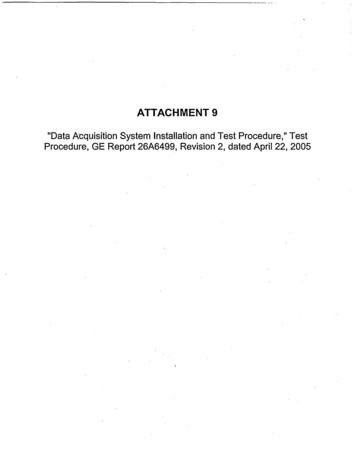
Data Acquisition: LabVIEWLabVIEW is a popular professional programming environment for data acquisition andinstrumentation. It is integrated into the course mainly as an environment that lends itself to thecontrol of testing environments such as vehicle component testing.LabVIEW instrumentation and control software from National Instruments is based onoptimizing data flow as opposed to optimizing sequential structure as in tradition programming.The programming uses a graphical format with a Front Panel that represents the user’s GUI. TheBlock Diagram contains the code with the programming performed in a graphical format.Programs in LabVIEW are called Virtual Instruments or VIs.LabVIEW programs should be coded to follow standard design patterns to organize the code,enhance functionality, and foster efficient troubleshooting. Example standard design patternsinclude simple loops, Master/Slave loops to separate data acquisition and data processing, StateMachines, Event Structures, and other software design patterns. The use of Local and Global isnot recommended because data in these variables may be over-written. User-written FunctionalGlobal Variables or FIFO Queues are example techniques recommended to ensure data integrity.CAN communication can be performed in LabVIEW provided proper hardware is installed.Both Frame and Channel API are provided. Channel programming is easier for beginning users,but the Frame API does provide more control of some items such as buffer size. Examples ofCAN programming are included in the Example Finder when CAN hardware has been installed.A simple CAN application from the LabVIEW Example Finder is shown below. The FrontPanel is shown in Figure 4: Example CAN Application Front Panel, and corresponding BlockDiagram is shown in Figure 5: Example CAN Application Block Diagram.Page 15.341.10Figure 4: Example CAN Application Front Panel
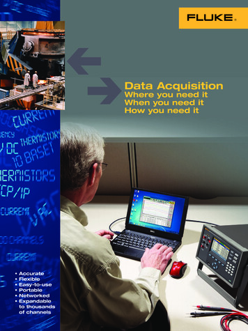
This example uses a standard loop pattern and CAN Channel API. The program is initializedbefore starting the loop, and the loop runs continuously with a 1ms wait each loop as set by thetimer icon. The loop will only stop if the STOP on the Front Panel is pushed, or if an erroroccurs during the loop. Once the loop is stopped, the tasks are cleared and resources released.Figure 5: Example CAN Application Block DiagramBefore using this example the corresponding CAN message and signal information would needto be entered in MAX. It is likely that CAN hardware will need to be installed before thisexample will be visible in the Example Finder.LabVIEW Real TimeThe engineering programs include a well established senior design project sequence. Anexample project that helps support the new vehicle instrumentation course is the Vehicle ChassisDynamometer that a senior design team refurbished during 2008-2009. It is now finding use inthe laboratory experiences of several courses. The dynamometer is shown below in Figure 6:Senior Design Project: Vehicle Dynamometer.Page 15.341.11Figure 6: Senior Design Project: Vehicle Chassis Dynamometer.
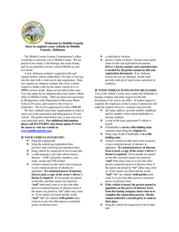
The dynamometer instrumentation and control software is a limited version of REPS, aprofessional, LabVIEW-based, Real Time, dynamometer software package from RevolutionaryEngineering23 The dynamometer control console contains the acquisition and control hardwareand a Real-Time industrial PC running LabVIEW Real Time software.Controller Area Network (CAN) Software: CANoeController Area Network (CAN) applications harness the power of distributed computingsystems in the form of independent micro-computer modules referred to as Engine Control Units(ECU). CAN networks and software are used in the automotive, heavy equipment, ship, andother vehicle industries. CANoe is a development platform for professional networkdevelopment software that includes CANdb (a message and signal database), CANalyzer (busanalysis tool), and CAPL (C-based bus programming environment).Students learn to use CANoe to simulate CAN network operation or to obtain data from a CANnetwork. They can also simulate nodes on an existing network and implement test scripts. ACANoe panel is shown below in Figure 7: CANoe Environment. The software configurationthat is demonstrated is a very simple demo configuration, called EASY, that is supplied with thesoftware. There are two messages, LightState and MotorState, being transmitted and received onthe bus. The message information can be seen on the far left window under Messages, and onthe bottom right Trace window.Page 15.341.12Figure 7: Vector CANoe Environment
The CANdb database for the Easy Confirmation is shown below in Figure 8: Vector CANdbDatabase. The CANdb contains the message and signal data.Figure 8: Vector CANdb DatabaseThe bus Simulation Setup is shown below in Figure 9: Vector CANoe Simulation Setup , andshows the simulated ECUs labeled LightSwitch, Motor, and MotorControl. This simulationcapability makes it easy to do network analysis and troubleshoot network problems. Studentscan also display and log bus signal data, insert pass or block filters, or generate test messages.Figure 9: Vector CANoe Simulation SetupPage 15.341.13
Two GUI Panels are part of this simulation. The Control GUI is shown in Figure 10: SimulationGUI Control, and Display GUI is shown in Figure 11: Simulation GUI Display. The status ofthe switches and controls on the Control GUI determine the signal values that are transmitted inthe bus messages. This signal information is captured by Display GUI. This figure shows thesimulated ECUs labeled LightSwitch, Motor, and MotorControl. This simulation capabilitymakes it easy to observe, analyze, and supplement data traffic on the bus.As part of the CAN instruction students learn how to create the database, setup a bus analysis orsimulation session, program node response using CAPL, and program the GUI displays.Figure 10: Simulation GUI ControlFigure 11: Simulation GUI DisplayCAN Access Programming Language (CAPL) is an Event-based language that allows simulationof a node on the network. CAPL is a C-based language that interfaces with the CAN Database,CANdb, and therefore has access to message and signal information. The CAPL Browser showsthe Browser Tree, Global variable declaration, script test, and message window.Page 15.341.14Portions of the CAPL Browser for the simulation GUI Control are shown below in Figure 12:CAPL Browser for Control. As mentioned earlier CAPL is an Event-based program. It runscontinuously while the simulation is active, and responds to Events such as receiving a specificmessage or a change in data of a specific signal. In this example the Browser is showing theCAPL code that would execute when message LightState is on the bus.
Figure 12: CAPL Browser for ControlAn example of CAPL code is shown below in Figure 13: CAPL Simple Example that causesMessage 1 to be periodically transmitted.variables{message 0x555 msg1 {dlc 6};msTimer timer1;}on start{setTimer(timer1,100);}on timer timer1{msg1.byte(0) msg1.byte(0) 1;output(msg1);setTimer(timer1,100);}Figure 13: CAPL Simple ExamplePage 15.341.15CAN programming gives students the background to enter the industrial setting and acquire keyvariable da
a context for the data acquisition and control laboratory activities. Course instr uction presents vehicle data acquisition applications while including discussions on the operation and tes ting of a generic electric vehicle drive train. An internal combustion vehicle and a vehicle chassis dynamometer are also used in the laboratory experience.