Transcription
Software-ControlledDigital CommunicationsPreliminaryMDS 05-4659A01, Rev. 0 JULY 2008Start-Up GuideMDS SD9
OPERATIONAL & SAFETY NOTICESRF ExposureConcentrated energy from a directional antenna may pose a health hazard tohumans. Do not allow people to come closer to the antenna than the distanceslisted in the table below when the transmitter is operating. More information onRF exposure can be found online at the following ntenna Gain vs. Recommended Safety Distance(MDS SD9 Radio)Antenna Gain0–5 dBiMinimum RFSafety Distance0.46 meter5–10 dBi.82 meters10–16.5 dBi1.74 metersFCC Part 15 NoticeUsers must comply with the following requirements:Operation of this device is subject to the following two conditions: (1) this device may not cause harmfulinterference, and (2) this device must accept any interference received, including interference that maycause undesired operation. Any unauthorized modification or changes to this device without the expressapproval of the manufacturer may void the user’s authority to operate this device. Furthermore, this deviceis intended to be used only when installed in accordance with the instructions outlined in this manual.Failure to comply with these instructions may void the user’s authority to operate this device.CSA/us NoticeThis product is pending approval for use in Class 1, Division 2, Groups A, B, C & D Hazardous Locations.Such locations are defined in Article 500 of the National Fire Protection Association (NFPA) publicationNFPA 70, otherwise known as the National Electrical Code. The transceiver has been recognized for usein these hazardous locations by the Canadian Standards Association (CSA) which also issues the US markof approval (CSA/US). The CSA Certification is in accordance with CSA STD C22.2 No. 213-M1987.CSA Conditions of Approval: The transceiver is not acceptable as a stand-alone unit for use in thehazardous locations described above. It must either be mounted within another piece of equipment whichis certified for hazardous locations, or installed within guidelines, or conditions of approval, as set forthby the approving agencies. These conditions of approval are as follows:The transceiver must be mounted within a separate enclosure which is suitable for the intended application.The antenna feedline, DC power cable and interface cable must be routed through conduit in accordance with the National Electrical Code.Installation, operation and maintenance of the transceiver should be in accordance with the transceiver'sinstallation manual, and the National Electrical Code. Tampering or replacement with non-factory components may adversely affect the safe use of the transceiver in hazardous locations, and may void theapproval. A power connector with screw-type retaining screws as supplied by GE MDS must be used.EXPLOSIONHAZARD!Do not disconnect equipment unless power has been switched off orthe area is known to be non-hazardous. Refer to Articles 500 through502 of the National Electrical Code (NFPA 70) for further informationon hazardous locations and approved Division 2 wiring methods.
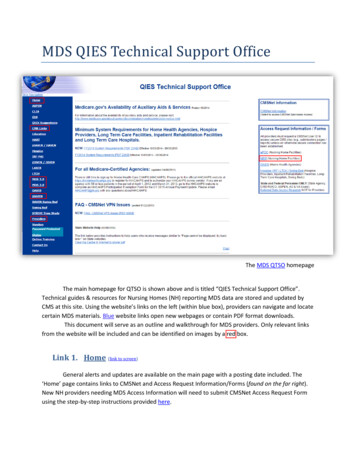
INTRODUCTIONThis guide presents basic installation and operating instructions for theMDS SD9 Series wireless transceiver.The transceiver (Figure 1) is designed to operate in point-to-multipoint environments, including utility automation/distribution systems,and other telemetry functions.These radios are software-configurable to provide flexible operationin a variety of applications using one hardware platform. They employmicroprocessor control and Digital Signal Processing (DSP) technology to provide robust communications even under adverse conditions.Figure 1. SD9 Data TransceiverThe transceiver is designed for trouble-free operation with data equipment provided by other manufacturers, including remote terminalunits (RTUs), programmable logic controllers (PLCs), flow computers, transaction terminals, and similar devices.NOTE: Some features may not be available on all units, based on theoptions purchased and the applicable regulatory constraintsfor the region in which the radio will operate.Front Panel ConnectorsFigure 2 shows the interface connectors and indicators on the transceiver’s front panel. These items are referenced in the installationsteps given later in this guide.05-xxxxA01, Rev. 01MDS SD9 Startup Guide1
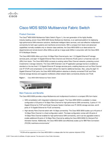
InvisibleplaceholderFigure 2. Front Panel Connectors & IndicatorsConnector functions (left to right) in Figure 2 are as follows: POWER LAN (RJ-45) COM1—Management/Diagnostics (DB-9) COM2—Payload Data (DB-9) ANTENNA (TNC)A list of LED functions is presented in Table 3 on Page 10.AccessoriesTable 1 lists available accessories for the transceiver. The contents ofa shipment may have been modified to reflect customer-specificrequirements given at the time of order. Additional accessories areavailable for our products. Contact your factory representative forassistance.2MDS SD9 Startup Guide05-xxxxA01, Rev. 01
Table 1. SD9 Available AccessoriesAccessoryDescriptionPart NumberDC Power Plug,2-pin, polarizedMates with power connector onradio. Screw terminals provided forwires, threaded locking screws toprevent accidental disconnect.73-1194A39Retrofit Kit, DigitalContains all items needed to replacean existing MDS x710A/C/M digitaltransceiver.98-6190ACC1Retrofit Kit, AnalogContains all items needed to replacean existing MDS x710A/C/Mtransceiver used in the analogmode.98-6190ACC2Reference ManualContains technical information,system design data, and a completelist of software commands.05-4670A01INSTALLATIONThere are three main requirements for installing the transceiver: Adequate and stable primary power An efficient and properly installed antenna system Correct data connections between the transceiver and the datadevice.Figure 3 shows a typical remote station arrangement. This is followedby step-by-step procedures for installing the transceiver and makingfront panel connections.05-xxxxA01, Rev. 01MDS SD9 Startup Guide3
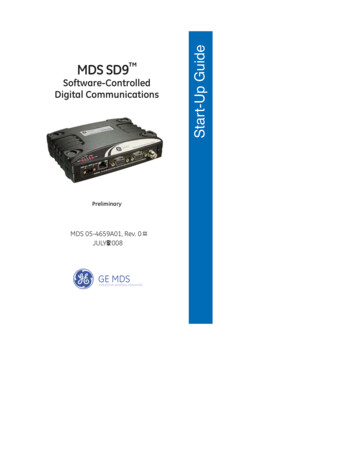
ANTENNASYSTEMTRANSCEIVERPOWER SUPPLY10.5–16 VDC @ 2ANegative Ground OnlyEINDLSOSEFE-LOWLDATA TELEMETRYDEVICEFigure 3. Typical Remote Station ArrangementInstallation StepsBelow are the basic steps for installing the transceiver. In most cases,these steps alone are sufficient to complete the installation. Refer tothe Reference Manual for additional details, if required.1. Mount the transceiver to a stable surface using the bracketssupplied with the radio. Begin by attaching the radio’s mountingbrackets to the bottom of the transceiver case (if not alreadyattached) using the four 6-32 x 1/4 inch (6 mm) screws supplied.Figure 4 shows the mounting bracket dimensions.NOTE: To prevent moisture from entering the radio, do not mount thecase with the cable connectors pointing up. Also, dress allcables to prevent moisture from running along the cables andinto the radio.4MDS SD9 Startup Guide05-xxxxA01, Rev. 01
2.75 (7 cm)Invisibleplaceholder7.25 (16.99 cm)Figure 4. Transceiver Mounting Bracket DimensionsCAUTIONPOSSIBLEEQUIPMENTDAMAGEUsing screws longer than 1/4 inch (6 mm) to attach thebrackets to the radio may damage the internal PCboard. Use only the supplied screws.2. Install the antenna and feedline for the station. Aim directionalantennas toward the master station. The antenna used with thetransceiver must be designed to operate in the radio’s frequencyband, and be mounted in a location that provides a clear path tothe associated master station. Use low loss coaxial feedline andkeep the cable as short as possible.3. Connect the data equipment to COM2 on the front panel. Theradio is hardwired as a DCE device. A straight-thru cable may beused in most applications. Check Table 5 on Page 14 for pin wiring details.Note: The radio’s LAN port is used for reprogramming the radio’sfirmware. Refer to the Reference Manual for details.4. Connect primary power to the transceiver. Power applied mustbe within 10.5–30 Vdc and capable of continuously providing atleast 2.5 Amperes. A power connector with screw-terminals is pro-05-xxxxA01, Rev. 01MDS SD9 Startup Guide5
vided with each unit (see Figure 5). Strip the wire leads to 6 mm(1/4 inch) and insert in the wire ports. Be sure to observe properpolarity as shown in the Figure 5.InvisibleplaceholderLeadBindingScrews (2)Wire Ports (2)RetainingScrews (2)(Polarity: Left , Right –)Figure 5. DC Power ConnectorCAUTIONPOSSIBLEEQUIPMENTDAMAGEThe transceiver is designed for use with negative-ground systems only. The power supply should beequipped with overload protection (NEC Class 2 rating),to protect against a short circuit between its output terminals and the radio’s power connector.5. Set the radio’s configuration. The transceiver is designed forquick installation with a minimum of software configurationrequired.a. Connect a PC to the transceiver’s DB-9 COM1 connector asshown in Figure 6. A straight-through cable may be used inmost applications. If desired, a cable may be built using theinformation shown on Page 12 of this guide.b. Launch a terminal communications program, such as HyperTerminal (included with most WindowsTM systems). Press theENTER key a few times (at half-second intervals) to receivethe ready “ ” prompt on the screen.NOTE: To prevent unintended keying of the transmitter duringmanagement activities, set PTTSIG to OFF, or do notconnect to Pin 6 of the COM1 port.6MDS SD9 Startup Guide05-xxxxA01, Rev. 01
InvisibleplaceholderTransceiverPC Running Terminal SessionTo COM1 PortFigure 6. PC Configuration Setupc. Set the transmit frequency by entering TX xxx.xxxx, wherexxx.xxxx is the frequency in MHz. Press ENTER . Theresponse PROGRAMMED OK indicates successful entry.d. Set the receive frequency by entering RX xxx.xxxx, wherexxx.xxxx is the frequency in MHz. Press ENTER . Theresponse PROGRAMMED OK indicates successful entry.e. Set the radio’s modem type if necessary, using the MODEMxxxx command, where xxxx is the modem selection (typically4800 or 9600). The default setting is 9600.f.Set the radio’s serial data interface rate (typically BAUD 96008N1).This completes the initial setup and configuration of the radio.05-xxxxA01, Rev. 01MDS SD9 Startup Guide7
SOFTWARE COMMAND SUMMARYTable 2 lists software commands commonly used during initial installation and setup of the transceiver. A complete list of commands anddetailed descriptions is contained in the Reference Manual.Table 2. Command SummaryCommand Name8FunctionBAUD [xxxx xxx]Sets radio’s serial data interface rate/format.Default setting is BAUD 9600 8N1.DATAKEYKeys the transmitter on receipt of data.DKEYDekey the radio (transmitter OFF). This isgenerally a radio test command.KEYKey the radio (transmitter ON). This isgenerally a radio test command.MODEM [xxxx]Set the modem characteristics of the radio.PORT [RS232, RS485]Selects signaling standard to be used onCOM2 DATA port. For RS-485 operation,see Reference Manual.PWR [20–37]Set or display the transmit power setting.PTTSIG [ON, OFF]Set/display push-to-talk configuration.RSSIDisplay the Received Signal StrengthIndication.RTSKEYSet/display how the radio responds to RTSkeying. Default is RTSKEY ON, whichcauses the radio to key the transmitter whenRTS is raised.RTU [ON/OFF/0-80]Re-enables or disables the radio’s internalRTU simulator and sets the RTU address.RX [xxx.xxxx]Set or display receiver frequency.SERDisplay the radio serial number.SNRSignal-to-Noise Ratio (in dB).SPECTRUM[xxx.xx]Display internal spectrum analyzer, wherexxx.xx characters denote center frequencyin MHz. The command spectrum may beentered alone to view current operatingchannel.SREVDisplay the Software Revision Level.MDS SD9 Startup Guide05-xxxxA01, Rev. 01
Table 2. Command Summary (Cont’d)Command NameFunctionSTATDisplay radio status and alarms.TEMPDisplay the internal temperature of the radioin degrees C.TX [xxx.xxxx]Set or display the transmit frequency.TROUBLESHOOTINGFor proper operation, all radios in the network must meet these basicrequirements: Adequate and stable primary power Secure connections (RF, data and power) A clear transmission path between stations An efficient and properly aligned antenna system providingadequate received signal strength. Proper programming of the transceiver’s operating parameters The correct interface between the transceiver and the connecteddata equipment (correct cable wiring, proper data format, timing, etc.)LED IndicatorsThe LED status indicators (Figure 7) are an important troubleshootingaid and should be checked whenever a problem is suspected. Table 3describes the function of each status LED on the top panel of the radio.In addition to the top panel LEDs, the ETHERNET/LAN connector hastwo integrated LEDs. A steady green LED indicates that an Ethernetlink has been established, a flashing green indicates data activity, anda yellow LED indicates 100 Mbps operation.05-xxxxA01, Rev. 01MDS SD9 Startup Guide9
InvisibleplaceholderFigure 7. LED IndicatorsTable 3. LED Status IndicatorsLED NamePWRDescription Continuous—Power applied, no problems detected. Rapid flash (5 times-per-second)—Alarm indication.LAN Continuous—Local area network detected. Flashing—Data is being transmitted and received. Off—LAN not detected or excessive traffic is present.COM1/COM2LINKThe COM LEDs show activity on the serial payload dataport(s). The left LED shows TX data and the right oneshows RX data.When lit, indicates that a communication link is establishedwith the master station.Event CodesWhen an alarm condition exists, the transceiver creates a code that canbe read on a connected terminal. These codes can be helpful inresolving many system difficulties. Refer to Table 4 (Page 11) for adefinition of the event codes.Checking for Alarms—STAT commandTo check for alarms, connect a terminal to the radio’s COM1 (diagnostics) connector. See “COM1 CONNECTIONS” on Page 12 for pinoutinformation.Enter STAT on the connected terminal. If no alarms exist, the messageNO ALARMS PRESENT appears on the display.If an alarm does exist, a two-digit alarm code (00–31) is displayed andthe event is identified as a Major or Minor Alarm. A brief descriptionof the alarm is also given.10MDS SD9 Startup Guide05-xxxxA01, Rev. 01
If more than one alarm exists, the word MORE appears on the screen.To view additional alarms, press ENTER .Major Alarms vs. Minor AlarmsMajor Alarms—report serious conditions that generally indicate ahardware failure, or other abnormal condition that will prevent (orseriously hamper) further operation of the transceiver. Major alarmsgenerally indicate the need for factory repair. Contact your factoryrepresentative for assistance.Minor Alarms—report conditions that, under most circumstances willnot prevent transceiver operation. This includes out-of-tolerance conditions, baud rate mismatches, etc. The cause of these alarms shouldbe investigated and corrected to prevent system failure.Event Code DefinitionsTable 4 contains a listing of event codes that may be reported by thetransceiver. The codes shown are a subset of a larger pool of codesused for various GE MDS products. For this reason, the table does notshow a sequential listing of all code numbers. Only the codes applicable to this product are shown.Table 4. Event CodesEventCodeEventClassDescription01MajorImproper software detected for this radio model.04MajorThe RF synthesizer is reporting an out-of-lockcondition.08MajorThe system is reporting that it has not beencalibrated. Factory calibration is required for properradio operation.12MajorReceiver time-out. No data received within thespecified receiver time-out time.13MinorA Transmitter timeout was detected. The radiostayed keyed longer than the duration specified bythe TOT command.17MinorA data parity fault has been detected on the COM2INTERFACE connector. This usually indicates aparity setting mismatch between the radio and theRTU.05-xxxxA01, Rev. 01MDS SD9 Startup Guide11
Table 4. Event Codes (Cont’d)EventCodeEventClassDescription18MinorA data framing error has been detected on theCOM2 INTERFACE connector. This may indicate abaud rate mismatch between the radio and the RTU.26MinorThe DC input voltage is out-of-tolerance. If thevoltage is too far out of tolerance, operation may fail.31MinorThe transceiver’s internal temperature isapproaching an out-of-tolerance condition. If thetemperature drifts outside of the recommendedoperating range, system operation may fail.Internal Spectrum AnalyzerThe radio contains a built-in spectrum analyzer tool that can be displayed on a connected PC. The tool is helpful in diagnosing interference problems on or near your channel frequency.Access the spectrum analyzer by entering spectrum at the commandprompt. A display appears showing detected signals on your currentchannel.Optionally, you can specify a frequency at the command prompt toview the surrounding spectrum of that frequency. To do this, enterspectrum xxx.xx, where xxx.xx is the frequency in MHz.The display creates a received signal strength indication (RSSI) vs.frequency plot for the frequency and surrounding signals. By analyzing the display, you can determine the presence of other signalsnear the transceiver’s operating frequency. This information can behelpful in troubleshooting interference problems.COM1/COM2 REFERENCECOM1 CONNECTIONSThe COM1 connector is used to connect a PC to the radio for management or diagnostics. A straight-through cable is required that connectsPin 2 (RXD), Pin 3 (TXD), and Pin 5 (Ground). (See Figure 8.)12MDS SD9 Startup Guide05-xxxxA01, Rev. 01
Invisibleplaceholder RXD2 RXDDB-9 MALE(RADIO SIDE)3 TXD 2TXD 3DB-9 FEMALE(COMPUTER)GND 55 GNDFigure 8. COM1 Wiring to ComputerNOTE: To prevent unintended keying of the transmitter duringmanagement activities, set PTTSIG to OFF, or do notconnect to Pin 6 of the COM1 port.COM2 CONNECTIONSThe COM2 connector (Figure 9) is used to connect the radio to anexternal DTE telemetry device that supports the EIA/RS-232 orEIA/RS-485 (balanced) format, depending on how the radio is configured. The radio supports data rates of 300, 1200, 2400, 4800, 9600,19200, 38400, 57600, and 115200 bps (asynchronous data only).The COM2 connector mates with a standard DB-9 plug that is available from many electronics parts distributors. Table 5 providesdetailed pin descriptions for the COM2 data connector in RS/EIA-232mode.NOTE:To prevent unintended keying of the transmitter on RTS, setRTSKEY to OFF, or do not connect to Pin 7 (RTS) of the COM2 port.51Figure 9. COM2 Connector (DB-9F)As viewed from outside the radio96Pin Descriptions—RS/EIA-232 ModeTable 5 lists the COM connector pin functions when configured tooperate in RS/EIA-232 mode. For RS/EIA-422/485 mode, refer to theReference Manual.05-xxxxA01, Rev. 01MDS SD9 Startup Guide13
NOTE: The radio is hard-wired as a DCE device.Table 5. COM2 Pin Descriptions—RS/EIA-232PinInput/Number Output1OUTPin DescriptionDCD (Data Carrier Detect/Link)—A low indicatessignal received.Digital Modem Selections: Digital carrier detectAnalog Modem Selections: Squelch indicator2OUTRXD (Received Data)—Supplies received data tothe connected device.3INTXD (Transmitted Data)—Accepts TX data from theconnected device.4INSleep Mode Input—Grounding this pin turns offmost circuits in a remote radio. This allows for greatlyreduced power consumption, yet preserves theradio’s ability to be quickly brought on line. (SeeUsing the Radio’s Sleep Mode” for details.)5--Signal Ground—Connects to ground (negativesupply potential) on chassis.6OUT7IN8OUT9--Alarm Output (DSR)—An RS-232 high/space( 5.0 Vdc) on this pin indicates an alarm condition.An RS-232 low/mark (–5.0 Vdc) indicates normaloperation. This pin may be used as an alarm output.(See Reference Manual.)RTS (Request-to-Send)—Keys the transmitter.CTS (Clear-to-Send)—Goes “high” after theprogrammed CTS delay time has elapsed (DCE), orkeys an attached radio when RF data arrives (CTSKEY).Reserved—User I/O for special applicationsNOTE: Additional information on Analog Mode operation (includingcable wiring details) is contained in the Reference Manual.14MDS SD9 Startup Guide05-xxxxA01, Rev. 01
SPECIFICATIONSGENERALFrequency Range*:MDS SD9: 920–960 MHz* Specific frequency authorizations are dependent on the type-approval ofradio. Consult the factory for details.RECEIVERMaximum Usable Sensitivity:–110 dBm at 1x10⁻⁶ BER (Preliminary)Bandwidth:12.5, 25 kHzTRANSMITTERCarrier Power:0.1 Watts to 5 WattsDuty Cycle:ContinuousOutput Impedance:50 ΩChannel Spacing:12.5, 25 kHzFCC Emission Designators:12.5 kHz B/W:25.0 kHz B/W:10K6F1D, F2D, F3D16K2F1D, F2D, F3DDATA CHARACTERISTICSSignaling Type:EIA/RS-232; DB-9 Female connectorCOM2 Data Rates:300–115200 bps, asynchronousData Latency:10 ms maximumPRIMARY POWERVoltage:13.8 Vdc Nominal (10.5 to 30Vdc)Negative-Ground Systems OnlyTX Supply Current:2.0 Amperes (Typical) @ 5 Watts RFOutputRX Supply Current:Operational—125 mA, NominalFuse:5-Ampere, internalENVIRONMENTALHumidity:95% at 40 degrees C (104 F),non-condensingTemperature Range:–40 to 70 degrees C (–40 F to 158 F)Weight:1.0 kilograms05-xxxxA01, Rev. 01MDS SD9 Startup Guide15
DIAGNOSTICS INTERFACESignaling Standard:Connector:RS-232 (COM1)RS-232/RS-485 (COM2)COM1—DB-9FCOM2—DB-9FSpecifications are subject to change without notice or obligation.16MDS SD9 Startup Guide05-xxxxA01, Rev. 01
Installation Guide
GE MDS, LLC175 Science ParkwayRochester, NY 14620General Business: 1 585 242-9600FAX: 1 585 242-9620Web: www.GEmds.com
(MDS SD9 Radio) Antenna Gain 0-5 dBi 5-10 dBi 10-16.5 dBi . This completes the initial setup and configuration of the radio. PC Running Terminal Session . 8 MDS SD9 Startup Guide 05-xxxxA01, Rev. 01 SOFTWARE COMMAND SUMMARY Table 2 lists software commands commonly used during initial instal-lation and setup of the transceiver. A .