Transcription
Sectional And Tilting Door OpenerInstallation Instructions and User GuideFS 10001000NS/NWARNINGPlease read the manual carefully before installation and use.The installation of your new door opener must be carried out by a technically qualifiedor licensed person.Attempting to install or repair the door opener without suitable technical qualificationmay result in severe personal injury, death and / or property damage.
CONTENTSImportant Safety Recommendations. . .1Product Description & Features.2-3Pre-Installation Recommendations .4Installation (Wall Bracket & Door Bracket) .4Installation (Steel Track) . .5Installation (Sectional Steel Track Assembly).6Battery Backup Assembly (optional).7Display Menu Instructions(Plus II).8Programming Instructions.9-19Terminal Introduction and Application.20-21Manual Disengagement.22Maintenance . . . .22Technical Specifications .23-24Parts Listing .25Common Fault & Solutions .26-27
IMPORTANT SAFETY RECOMMENDATIONSFAILURE TO COMPLY WITH THE FOLLOWING SAFETY RECOMMENDATIONS MAYRESULT IN SERIOUS PERSONAL INJURY, DEATH AND / OR PROPERTY DAMAGE.1. PLEASE READ CAREFULLY AND ADHERE TO ALL SAFETY AND INSTALLATIONRECOMMENDATIONS.2. The opener is designed and manufactured to meet local regulations. The installer must befamiliar with local regulations required in respect of the installation of the opener.3. Unqualified personnel or those persons who do not know the occupational health andsafety standards being applicable to automatic gates and other doors, must in nocircumstances carry out installations or implement systems.4. Persons who install or service the equipment without observing all the applicable safetystandards will be responsible for any damage, injury, cost, expense or claim whatsoeverany person suffered as a result of failure to install the system correctly and in accordancewith the relevant safety standards and installation manual whether directly or indirectly.5. For additional safety we strongly recommend the inclusion of Photo Beam. Although theopener incorporates a pressure sensitive Safety Obstruction Force system the addition ofPhoto Beam will greatly enhance the operating safety of an automatic garage door andprovide additional peace of mind.6. Make sure that the garage door is fully open & stationary before driving in or out of thegarage.7. Make sure the garage door is fully closed & stationary before leaving.8. Keep hands and loose clothing off the opener and garage door all the time.9. The Safety Obstruction System is designed to work on STATIONARY objects only.Serious personal injury, death and / or property damage may occur if the garage doorcomes into contact with a moving object10. This appliance is not intended for use by persons (including children) with reducedphysical, sensory or mental capabilities, or lack of experience and knowledge, unless theyhave been given supervision or instruction concerning use of the appliance by a personresponsible for their safety. Children should be supervised to ensure that they do not playwith the appliance.11.Waste electrical products should not be disposed of with household waste. Pleaserecycle where facilities exist. Check with your local authority or retailer for recyclingadvice.12. If the supply cord is damaged, it must be replaced by the manufacturer, its service agentor similarly qualified persons in order to avoid a hazard.- WARNING: Important safety instructions. It is important for the safety of persons to followall instructions. Save these instructions.- Do not allow children to play with door controls. Keep remote controls away from children.- Watch the moving door and keep people away until the door is completely opened orclosed.- Take care when operating the manual release since an open door may fall rapidly due toweak or broken springs, or being out of balance.- Frequently examine the installation, in particular check cables, springs and mountings forsigns of wear, damage or imbalance. Do not use if repair or adjustment is needed since afault in the installation or an incorrectly balanced door may cause injury.- Each month check that the drive reverses when the door contacts a 50 mm high objectplaced on the floor. Adjust if necessary and recheck since an incorrect adjustment maypresent a hazard, for drives incorporating an entrapment protection system depending oncontact with the bottom edge of the door.- Details on how to use the manual release.- Information concerning the adjustment of the door and drive.- Disconnect the supply when cleaning or carrying out other maintenance.- The installation instructions shall include details for the installation of the drive and itsassociated components.1
PRODUCT DESCRIPTION & FEATURES1. Obstruction force adjustmentThe minimum force display “1” and it can be adjusted upward. Display “5” means themaximum force.2. Travel speed adjustment“8” appears on the display means the 80% of the travel speed. Display “A” means thefull speed 160mm/s or 200mm/s.3. Reversal height adjustment“0” appears on the display means the door will rebound to the top. Display “1 9”means the door will rebound to the position of the whole travel. One tenth to Nine tenth of thewhole travel etc.4. Partial open/height“0” appears on the display means close the partial open function. Display“1 9” meansto set the different partial open position of the whole travel.5. Transmitter button recognition function“0” appears on the display means the buttons recognition function is closed. Display“1”means the buttons recognition function is open.6. Codes memory quantity“A” appears on the display means the maximal code memory quantity is 50pcs. PressUP/DOWN button once, to increase or decrease quantity. The code memory quantity is set on5pcs*N, N 1 9. (The quantity is the multiple of 5).7. Maintenance alarm“b”appears on the display and led light flashes 10 times quickly means the garage doorand motor need total maintenance.8.Automatic safety reverseAutomatic stop / automatic reverse are controlled by our software of circuit boards. Weare circumspect to protect your children, pet or other goods.9.Soft start / Soft stopRamping speed up and down at the start and end of each cycle reduces stress on thedoor and opener for longer life, and makes for quieter operations.10. Auto-CloseAuto- Close ensures peace of mind and keeps your house secure by automatically closingthe door upon entering or exiting the garage.11.Self learning open and close obstruction forceThe amount of opener power for different stages of the door’s travel is learnt during setupand is constantly re-profiled. Opener force measurement automatically adjustment in asuitable range.12.Electronic limit, simple adjustment.You only need control the limit setup from control panels to adjust it exactly, the simpleand quick process for any peoples.13. Available terminal for Photo beams & Extra receivers & Wire or wireless wall switch& Caution light & Pass door protection device.14.Energy saving - L.E.D courtesy light3 minutes L.E.D light delay, switching on with each cycle to illuminate your darkenedgarage.2
15.Battery backup availableOpeners could be supplied power with our battery backup once the power failure at yourhome.16.Self-Lock in gear motorsGear motor will self-lock with its disengagement systems.17.Manual releaseDon't worry about the power failure, the manual release system is a solution for operationthe door at any time.18.Transmitter technologyRolling Code technology (7.38 x 10¹⁹ Combinations), 433.92 MHz frequency, 4 channelsdesign to ensure you can control 4 different doors with one transmitter.19.ApplicationsWith as little as 30mm required between the ceiling and the highest point of the door travel,the opener can be flush mounted for low headroom applications.20.Metal bottom plate, stronger and security.21.Up / Down moving operation buttons (UP / DOWN)OpenClose3
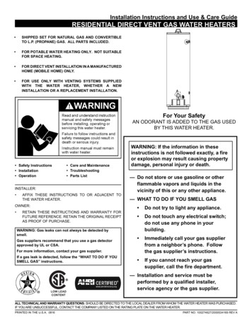
PRE-INSTALLATION RECOMMENDATIONS1. Garage door must be able to be lifted and closed easily by hand and without much effort. Awell balanced & sprung door is critical for proper installation.2. The garage door opener can’t compensate for a badly installed garage door and shouldnot be used as a solution for a “hard to open” door.3. If the unit is being installed on an existing door, make sure any existing locking devices areremoved or warranty will be void.4. An approved outlet must be installed near where the opener is begin installed.5. There should be a minimum gap of 30mm between the bottom of the chain drive rail andthe top of the garage door at its closest point. (refer to Fig 1.)Important note: As for additional safety rules, we strongly recommends the fitting of PhotoElectric safety beams on all installations.Figure 1INSTALLATION INSTRUCTIONSMount Wall Bracket and Door Bracket (Fig2)Wall Bracket - Close the garage door and measure thegarage door width at the top and mark the centre. Locate andmount the wall bracket 2cm-15cm above the door on theinside wall.(Depend on the actual installation space).Door Bracket – Fix the door bracket to a structural part of thedoor as close to the top edge as possible.Figure 24
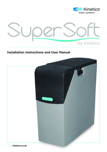
Installation (Steel Track)Figure 3STEP1 (Fig.3)Attach the opener head to the steel track. Assembly the 2 “U” Hanging brack etswith 6mm nuts supplied.STEP2 (Fig.3)Place the steel track and opener head assembly centrally on the garage f loor, withthe open head furthest away from the door. Lift the front of the track up to the doorbracket. Insert the pivot pin and secure it with the split pin supplied.STEP3 (Fig.3, Fig.4)Lift and support the opener head (with a ladder) so it ispositioned centrally and level. Fix the opener and trackon ceiling by Iron bracket A & B.WARNING: Do not allow children around the door,opener or supporting ladder serious injury and/ordamage may result from failure to follow this warning.STEP4 (Fig.3, Fig.5)Connect the straight arm to the bent arm with the bolt.Position and bolt the arms to the top edge of the door usingthe bolt supplied.STEP5Lift the garage door until the shuttle locks into thedrive chain/belt.Now, ready to program the openers.5
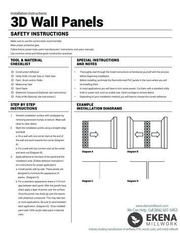
Sectional Steel Track Assembly2 Parts Steel TrackA:1500 mmB:1500 mmSleeve3 Parts Steel TrackD:1000 mmC:1000 mmE:1000 mmSleeveSleeve1. 2-Parts Track:As Fig.6, slide the A rail into the sleeve, slide the B rail into the sleeve.3-Parts Track:As Fig.7, slide the C rail into the sleeve, slide the D rail into the sleeve; slide the E rail intothe sleeve.2. Cut the plastic thread; pull the screw rod along with inner chain to the end rail position(Fig.8)FF3. As Fig.9, release the nut & spring.4. Tight the nut to the right position as shown in Fig.10, cut the plastic tape, cut the plasticthread on sprocket, then whole rail assembled finished.6
Battery backup Assembly (optional)Option 1 - Top FixedSTEP1 (Fig.11)Assemble the battery & battery bracket like the photo, fix by screws supp lied.STEP2 (Fig.12)Join the battery to opener, find the Fig.12.Figure 11Figure 12Option 2 - Side FixedSTEP1 (Fig.13)Assemble the battery & battery bracket like the photo, fix by screws supplied .STEP2 (Fig.14)Join the battery to opener, find the Fig.14.Figure 13Figure 147
DISPLAY MENU INSTRUCTIONSFEATURES SETTINGS:a)Press and hold SET button until “1” appears on the display then releasethe button.b)Press UP / Down button, then it displays the number “1-E”.c)Press Set button to confirm the feature you need to set, then it enters tothe interface for detail setting of the appointed feature.d)In the detail setting interface display “0-A” with flash dot.e)Press UP / Down button to choose the feature you need to set.f )Press SET button to confirm the set and it will back to standby statusautomatically and display “ll”.8
PROGRAMMING INSTRUCTIONSPre- Instruction for programme buttons1. Short click SET button : When it standby, it will clear the error, alarm display, andreturn to normal display.2. Short click CODE button : ( In the Setting Status) Exit the current operation and return to the standbyinterface. When it standby, press the code, A dot will be indicated in the corner, nowentering the code leaning mode.Now first click the button on the hand transmitter you want to use, the dot maydisappear ,then press again the same button on the hand transmitter, the dot will flash,here, the code learning is finished.3. Short press UP button : The door will open.4. Short press DOWN button : The door will close.(When the door is opening or closing, it will stop if you press any key.)5. Long press SET button : Enter function setting interface.6. Long press CODE button : Press and hold CODE button until a C is indicated on thedisplay. All stored remotes will be deleted.7. Long press UP button : Increase the resilience. (Keep press DOWN button, after 4seconds, it will scroll to display 0-1-2, choose the number you want. 1 increase 25%2 increase 50%)8. Long press DOWN button : Restore Factory SettingsKeep press DOWN button, after 4 seconds, it will scroll to display, then thegarage door opener will restart.Restart means all settings are back to factory settings, all learning things need to be doneagain except the transmitter code learning.9
PROGRAMMING INSTRUCTIONS1. PROGRAMMING OPEN & CLOSE LIMITSa) Press and hold SET button to enter this function settinguntil “1” appears on the display then release the button.b) Press the SET button again. The door opener is now inProgramming Mode. And then you will see “n” with dotappears on the display.c) Press and hold the UP button until the door reaches thedesired open position, you will see “n” without dot on thedisplay.d) Press SET button to confirm the open position, then youwill see “u” with dot on the display.e) Next press and hold the DOWN button until the doorreaches the desired close position, you will see “u” withoutdot on the display.NOTE: For fine adjustments toggle UP & DOWNbuttons.f) Now press the SET button to confirm the close position,then you will see “II” on the display.After confirm the close position, the door will now cycle openand close to set the travel limits and force sensitivityadjustments. The door is now set for normal operation.CAUTION: After the cycle open and close, there will befigures shown on the display (0 9), “0” means the doors isbalanced, the smaller figure means the better door balance,strongly recommend that the figure need to be smaller thanthe power force.10
2. OBSTRUCTION FORCE ADJUSTMENTCAUTION: The obstruction force adjustment is set automaticallyduring programming. Normally no adjustment is necessary.a) Press and hold SET Button until “1”appears on the display, nextpress the UP Button until “2” appears on the display to enter thisfunction setting then release the button.Increase forceb) Press the SET button again, The unit is now in force adjustmentmode. And then you will see a figure “3” with flash dot appears on thedisplay.c) Press the UP button to increase the force setting or the DOWNbutton to decrease the force setting.Decrease forceThe minimum force is “ 1 ” and it can be adjusted upward. Themaximum force is “5”.d) PressSPEEDSET buttonto confirm the set and it will back to standby3. TRAVELSETTINGCAUTION: If you changed the speed again, it will cancel thestatus automatically and display “ll”.previous travel limit. The speed adjustment function will beavailable only after you reset the travel limit.NOTE: The force is set on “3” as standard in factory.a) Press and hold SET Button until “1”appears on the display, nextpress the UP button until “3” appears on the display to enter this functionsetting then release the button.Increase speedb) Press the SET button again. The unit is now in speed adjustmentmode. And then you will see a letter “A” with flash dot appears on thedisplay.c) Press the UP & DOWN button to choose the speed. Figure “8”means the 80% of the travel speed. Figure “A” means the full speed.Decrease speedd) Press SET button to confirm the set and it will back to standbystatus automatically and display “ll”.NOTE: The travel speed is set on full speed “A” as standard in factory.11
4. AUTOMATIC CLOSING&TIME SETTINGNOTE: We recommend that Safety Photo Beams be used in anyinstallation where the Auto Close function is enabled.a) Press and hold SET Button until“1”appears on the display, nextpress the UP button until “4” appears on the display to enter this functionsetting then release the button.b) Press the SET button again, the unit is now in automatic closeIncrease timeadjustment mode. And then you will see a figure “0” with flash dotappears on the display.c) Press UP / Down button once to set the auto close time (0 9).d) Press UP button to increase the time, or DOWN button to decreaseDecrease timethe time.The close time is 15second*N, N 0 9. The maximum time is 135s. Todisable Auto Close Function, set time to zero (0).e) Press SET button to confirm the set and it will back to standbystatus automatically and display “ll”.NOTE:1.The closing time is set on “0” as standard in factory.2. If the Photo Cell Function is on, and it ’ s broke by theobstruction, the auto close time will stop for a while, and then continue theautomatic close time again.12
5. AUTOMATIC CLOSING CONDITION SETTINGa) Press and hold SET Button until “1” appears on the display, nextpress the UP button until “5” appears on the display to enter thisfunction setting then release the button.b) Press the SET button again. The unit is now in automatic closecondition adjustment mode. And then you will see a figure “1” with flashdot appears on the display.Increasec) Press UP / Down button once to set the auto close condition. Youcan choose “1” or “2” set.Figure “1” means, the door only can auto close while in the openDecreaselimit position.Figure “2” means, the door can auto close while the door is in anyposition.d) Press SET button to confirm the set and it will back to standbystatus automatically and display “ll”.NOTE:TheDELAYclosing TIMEconditionis set on “1” as standard in factory.6. LED1.OFFSETTING2. The door will only automatic close while in its opening process,a) Press and hold SET Button until “1” appears on the display, nextbut can’t automatic close after it is stopped while in its closing process.press the UP button until “6” appears on the display to enter thisfunction setting then release the button.b) Press the SET button again. The unit is now in LED off delay timeadjustment mode. And then you will see a figure“3”with flash dot appearsIncrease timeon the display.c) Press UP / Down button once to set the LED off delay time (1 9).d) Press UP button to increase the time, or DOWN button todecrease the time.The delay time is 1 minute*N, N 1 9. The maximum delay time is 9Decrease timeminutes.e) Press SET button to confirm the set and it will back to standby13status automatically and display “ll”.
7. REVERSAL HEIGHT SETTINGa) Press and hold SET Button until “1” appears on the display, nextpress the UP button until “7” appears on the display to enter this functionsetting then release the button.b) Press the SET button again. The unit is now in reversal heightIncrease heightadjustment mode. And then you will see a figure “0” with flash dot appearson the display.c) Press UP / Down button once to set the reversal height while closing(0 9).d) Press UP button to increase , or DOWN button to decrease.Decrease heightFigure “0” means the door will rebound to the open limit position.Figure “1 9” means the door will rebound to the position of the wholetravel. One tenth to Nine tenth of the whole travel etc.e) Press SET button to confirm the set and it will back to standby statusautomatically and display “ll”.NOTE: The reversal height is set on “0” as standard in factory.14
8. PARTIAL OPEN/HEIGHT SETTINGa) Press and hold SET Button until “1” appears on the display, nextpress the UP button until “8” appears on the display to enter thisfunction setting then release the button.Increaseb) Press the SET button again. The unit is now in partial-open/heightadjustment mode. And then you will see a figure “0” with flash dotappears on the display.c) Press UP / Down button once to select if you want to open thepartial open function or set the partial open height. (0 9). Press UPbutton to increase , or DOWN button to decrease.DecreaseFigure “0” means close the partial open function.Figure “1 9” means set the partial open position of the whole travel.One tenth to Nine tenth of the whole travel etc.d) Press SET button to confirm the set and it will back to standbystatus automatically and display “ll”.15
9. TRANSMITTER BUTTONS RECOGNITION FUNCTION SETTINGa) Press and hold SET button to enter this function setting until “9”appears on the display then release the button.b) Press the SET button again. The unit is now in buttons recognitionfunction adjustment mode. And then you will see a figure “1” with flash dotappears on the display.c) Press UP / Down button once to select if you want all the 4 buttonscan control the only one opener, or only the separate coded button cancontrol the opener.Figure “0” means the buttons recognition function is closed. It meansif you coded 1 button with 1 opener, then all the 4 buttons on theremote can control the opener. It’s suit for the users who only have 1Buttons recognition function is closedautomation door at home.Figure “1” means the buttons recognition function is open. If youcoded first button with first opener, then the first button will be the onlybutton on the remote can control the opener. It’s suit for the users whoButtons recognition function is openhave more than 1 automation doors/gates at home.d) Press SET button to confirm the set and it will back to standby statusautomatically and display “ll”.NOTE: 1. The buttons recognition is set on “1” as standard in factory.A. CODES MEMORY QUANTITY SETTING2. After you changed the buttons un-recognition into recognition,a)Pressand he display, nextplease notice thatcodedbuttonthe onopener.press the UP button until “A” appears on the display to enter this functionsetting then release the button.b) Press the SET button again, the unit is now in remote quantityadjustment mode. And then you will see a figure “A” again, but with flash dotappears on the display.Increase quantityc) Press UP / Down button once to set the remote quantity. (A or 1 9).d) Figure “A”means the maximal quantity 50pcs. Press UP/DOWNbutton once to increase or decrease quantity.Decrease quantityThe remote quantity is set on 5pcs*N, N 1 9. (The quantity is themultiple of 5)e) Press SET buttonto confirm the set and it will back to standby status16automatically and display “ll”.NOTE: The remote quantity is set on “A” as standard in factory.
b. REVERSAL HEIGHT IGNORANCE SETTINGa) Press and hold SET Button until “1” appears on the display, nextpress the UP button until “b” appears on the display to enter this functionsetting then release the button.b) Press the SET button again. The unit is now in reversal heightignorance adjustment mode. And then you will see a figure “1” with flashIncrease heightdot appears on the display.c) Press UP / Down button once to set the reversal height ignorancewhile closing (0 9).d) Press UP button to increase , or DOWN button to decrease.Decrease heightFigure “1 9” means the door will still not rebound even thoughthere’s obstacles in its closing path within 1cm 9cm away from theclose position. This function is most suitable for the NorthernEurope where will always snow on the ground.e) Press SET button to confirm the set and it will back to standbystatus automatically and display “ll”.C. PASS DOOR SWITCH TYPE SETTINGa) Pressand holdSETisButtonappears inonfactory.the display, nextNOTE:The reversalheightset onuntil“1” “1”as standardpress the UP button until “C” appears on the display to enter this functionsetting then release the button.b) Press the SET button again. The unit is now in the pass door switchtype adjustment mode. And then you will see a figure “0” with flash dotappears on the display.c) Press UP / Down button once to set the pass door switch type. Youcan choose “0” or “1” set.Figure “0” means, the pass door function is normally open.Figure “1” means, the pass door function is normally close.17e) Press SET button to confirm the set and it will back to standby
d. PHOTO CELL ON/OFF SETTINGNOTE: Make sure the photo cell has been correctly installed and usedNormally Closed contacts to the accessory terminals of the opener.Also note that the photo beam function must be disabled if NO photobeams are fitted, otherwise the door cannot be closed, and the LEDdisplay will show the letter“ r ”as an indication.a) Press and hold SET Button until “1” appears on the display, nextpress the UP button until “d” appears on the display to enter this functionsetting then release the button.b) Press the SET button again. The unit is now in the photo cell ON/OFFadjustment mode. And then you will see a figure “0” with flash dot appearson the display.c) Press UP / Down button once to set the photo cell ON/OFF switch.You can choose “0” or “1”set.Figure “0” means, the photo cell function is closed.Figure “1” means, the photo cell function is open.d) Press SET button to confirm the set and it will be back to standbystatus automatically and display “ll”.NOTE: The photo cell is set on “0” as standard in factory.18
E. MAINTENANCE ALARM--OPERATION CYCLES COUNT SETTINGa) Press and hold SET Button until “1” appears on the display, nextpress the UP button until “E” appears on the display to enter this functionsetting then release the button.b) Press the SET button again. The unit is now in the maintenance alarmadjustment mode. And then you will see a figure “0” with flash dot appearson the display.c) Press UP / Down button, you can select the operation cycles youneed the opener to make you notice. You can choose from “1-5” set.Figure “1” means, after garage door operated to 1000 times, the L.E.Dlight will flash 10 times quickly after the door stop working every time.In order to make you notice that your garage door need to domaintenance . And at the same time, you will see a figure “t” appearson the display.Figure “2” means the maintenance alarm count cycle is set on 2000times.Figure “3” means the maintenance alarm count cycle is set on 3000times.Figure “4” means the maintenance alarm count cycle is set on 4000times.Figure “5” means the maintenance alarm count cycle is set on 5000times.c) Press SET button to confirm the set and it will be back to standby statusautomatically and display “ll”.NOTE: 1. The operation cycles count is set on “0” as standard in factory.F. OPEN2./ “b”STOPappears/ CLOSEon displayTERMINALSand led light flashes 10 times quicklymeans the door lost balance, strong recommend the maintenance for garageThe O/S/C facility can be used for an external push button switch to operatedoors.the opener.The switchmust havevoltage freeopencontacts.3. “Check”the status,or “ Re-learn”thenormallytravel limitaftermaintenancealarm cautions.19
Photo beam connection (optional) – Fig.15,Fig.16Switch control connection (optional) – Fig.15Remark:1. Flash (Caution Light) Should be less than 25W.2. PB (External Push Button) Should be “ NO”.Figure 15Figure 16Other terminal introduction and application1.The O/S/C interfaces available.(Fig. 17, Fig. 18)Add a new O/S/C button to open or close the door.2.Flash light function. (Fig. 17, Fig. 18)There are corresponding interfaces for this function and provide 24v-35v flash light voltage.Connect the flash light with DC 24v-28v, current 100mA. When use AC 220V power flashlights, please match an adapter, and wiring as required3.Pass door (SD) protection (Fig. 17, Fig. 18)This function ensures that the door can’t be opened unless the small pass door is closed.The door panel won’t be damaged.20
Figure 17Figure 1821
MANUAL DISENGAGEMENTThe opener is equipped with a manual release cord to disengage shuttle and move door byhand while holding the handle down (Fig 19). Pull on the handle to disengage the shuttle. Tore-engage the door simply run opener in automatic mode or move door by hand until the trolleyengages in the chain shuttle.In some situations that a pedestrian door is not in state, it is recommended that an externaldisengagement device should be fitted (Fig 20).Figure 19Figure 20MAINTENANCE1.No particular maintenance is required for the logic circuit board.Check the door at least twice a year if it is properly balanced, and all working parts are ingood working condition or not.Check the reversing sensitivity at least twice a year, and adjust if it is necessary.Make sure that the safety devices are working effectively (photo beams, etc.)2.Light bulb replacing:Notice: Make sure the power supply has been cut off before replacing the light bulb. Andensure the voltage of the new light bulb is in accordance with the local voltage and thepo
Wall Bracket - Close the garage door and measure the garage door width at the top and mark the centre. Locate and mount the wall bracket 2cm-15cm above the door on the inside wall. (Depend on the actual installation space). Door Bracket - Fix the door bracket to a structural part of the door as close to the top edge as possible.