Transcription
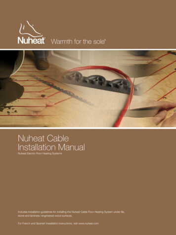
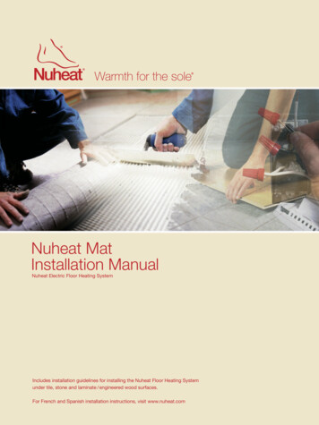
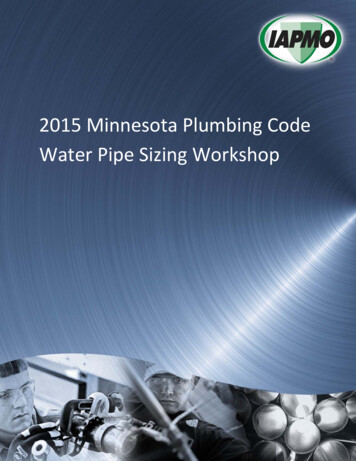
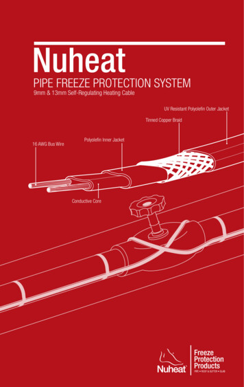
NuheatPIPE FREEZE PROTECTION SYSTEM9mm & 13mm Self-Regulating Heating CableUV Resistant Polyolefin Outer JacketTinned Copper Braid16 AWG Bus WirePolyolefin Inner JacketConductive Core
Nuheat Industries Limited 2010 Nuheat Industries Limited. All rights reserved.The entire contents of this manual, including but not limited to text, images, and the selection andarrangement of information (collectively the “Materials”), are protected by copyright and otherintellectual property laws under the laws of Canada and other countries.ATTENTION: The installation of this heating product shall be in accordance with themanufacturer’s instructions and in accordance with the Canadian ElectricalCode Part 1 or the National Electrical Code (US) whichever is applicable. This equipment shall be installed only by qualified personnel who are familiarwith the construction and operation of the apparatus and risks involved. Caution should be taken to guard against risk of electric shock, fire andbodily injury during the installation of this equipment. Indicate on the electrical panel which circuit is used for the Nuheat FreezeProtection Product.Nuheat Pipe Freeze Protection System Installation Guide
Section 1: Pre-installation1.1Important Installation Guidelines . 61.2Before You Start . 71.3System Components . 81.4Insulation & Continuity Tests . 101.5Insulation Resistance Table . 121.6Warranty Information . 131.7Special Installation Considerations . 151.8Pre-Installation Checks . 16Section 2: Installation2.1Overview . 182.2Cable Layout . 192.3Securing the Cable . 212.4Power Connection . 242.5Thermostat . 242.6Insulation . 252.7Post-Installation Checks . 26Section 3: Electrical Connections & Controls3.1Typical Wiring Diagram . 283.2Repairs and Maintenance . 283.3Appendix 1:Heat Loss for Metal Pipes . 29Appendix 2:Heat Loss for Plastic Pipes . 30Appendix 3:Maximum Circuit Lengths . 31Nuheat Pipe Freeze Protection System Installation GuideTable of contentsTable of Contents
pre-installation1.1Important installation guidelines61.2before you start71.21Tools. 71.22Materials . 71.3 System Components81.31Pipe Freeze Protection System Overview . 81.32Pipe Freeze Protection Heating Cable . 81.33Power Connections, Splices, End Seals . 91.34Tape . 91.35Pipe Insulation . 91.36Warning Labels / Stickers . 91.37Control . 91.4Insulation & Continuity Tests101.41Insulation Test . 111.42Continuity Test . 111.43Frequency of Testing. 111.44Circuit Length Verification Test . 111.5Insulation Resistance Table1.6Warranty info131.61Warranty Terms . 131.62How to Claim this Warranty . 131.63Disclaimer . 131.64Warranty Coverage . 14121.7 Special Installation considerations151.71Pipes Entering a Building. 151.72Pipes Entering Underground . 151.8Pre-Installation Checks16Nuheat Pipe Freeze Protection System Installation GuideSECTION 1SECTION 1
SECTION 11.1 pre-installation 1.1 Important Installation guidelines Important Installation GuidelinesDo not energize the cable(s) before installation is complete.Ensure bus wires of the same cable are separated. Bus wires will short ifthey contact each other when energized.Cable ends must be terminated with Nuheat end seals. Bus wires cannot beleft exposed.Bus wires and cable terminations should be kept dry before, during, andafter installation.Ensure drip loops are made with the cables or conduits to prevent waterfrom trailing into any electrical equipment, junction boxes, or controls.Be careful not to break bus wire strands when isolating the bus wiresduring splice connections. Damaged bus wires can overheat or may causea short circuit.Only use Nuheat connection components to make splices and/or endterminations. Nuheat connection components are certified and approvedfor use with Nuheat self-regulating cables.Observe the maximum circuit lengths of the cable (Appendix 3 on page 31)and do not exceed this limit during the installation. Exceeding the maximumcircuit lengths will result in breaker trips which will prevent the heating cablefrom turning on in freezing conditions.Conduct insulation and resistance tests at various times before, during, andafter installation. Refer to testing procedures on page 10 of this guide.Testing and visual inspections should be performed after any type ofmaintenance or repair including but not limited to cleaning, re-insulating,and installation/addition of pipe segments or features.Test and ensure pipe freeze protection system is functioning properly priorto each winter season.Materials used for the housing (i.e. junction boxes), support or on which thecables are installed shall be grounded in accordance with CSA standardC22.1, section 10.All installations must be in compliance with the following electrical codes:o Articles 426 and 500 of the NEC (National Electrical Code)o Sections 62 and 18 of the CEC (Canadian Electrical Code)o IEEE Standard 515.1-2005NUHEAT INDUSTRIES AND NEC REQUIRE 30-MA EQUIPMENT GROUNDFAULT PROTECTION ON EACH HEATING CABLE BRANCH CIRCUIT.6Nuheat Pipe Freeze Protection System Installation Guide
SECTION 11. 2 Before You StartThe following tools /materials are required for the Nuheat Pipe Freeze ProtectionSystem installation: before you start1.21 Tools1000Vdc megohmmeterMultimeterMethod to payout / unreel the heating cableCutting pliers Tape used to secure heating cable to the pipeo Glass cloth tapeAluminum tape (for plastic pipes only)Materials needed for electrical connectionso Nuheat approved connection kitso Junction boxeso Suitable conduit for various connectionsPipe insulationWeatherproof cladding (for outdoor pipe applications only)Nuheat Pipe Freeze Protection System Installation Guidepre-installation 1.21.22 Materials7
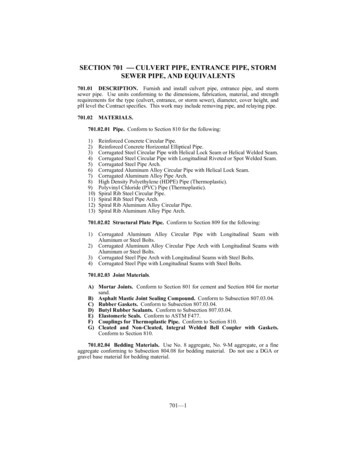
SECTION 11. 3 System components1.31 Pipe Freeze protection System OverviewGlass Cloth Tapepre-installation12”1.3Heating CableSystem ComponentsPipe InsulationWarning LabelFIGURE 1.31: Pipe Freeze Protection SystemNuheat pipe freeze protection cables are fastened to plastic or metallic pipes.The heating cable may be installed in single or in multiple runs based on designrequirements. Nuheat pipe freeze protection cables are self-regulating and may beoverlapped and crossed if necessary without risk of overheating or burnout.1.32 Pipe Freeze protection Heating CableUV Resistant Polyolefin Outer JacketPolyolefin Inner JacketTinned Copper BraidConductive Core16 AWG Bus WireFIGURE 1.32: Pipe Freeze Protection Self-Regulating Heating Cable8Nuheat Pipe Freeze Protection System Installation Guide
SECTION 11. 3 System components1.33 Power Connections, Splices, End SealsSystem ComponentsSpecific connection kits are required to connect heating cables to power, splice/splitcables along piping branches, and terminating cable ends.1.34 TapeNuheat pipe freeze protection cables are fastened to the pipes using glass cloth tape.1.35 Pipe Insulationpre-installation1.3After the heating cables are fastened to the pipes, the pipe must be insulated.Fiberglass pipe insulation is commonly used.1.36 Warning Labels/StickersWarning labels and stickers are placed above the pipe insulation to indicate thelocation of splices and end seals and also to indicate the presence of electric heattracing cables.1.37 ControlLine-sensing (recommended) or ambient-sensing thermostats can be used to controlwhen the heating cables turn on/off.Nuheat Pipe Freeze Protection System Installation Guide9
SECTION 11. 4 Insulation & Continuity Testspre-installationInsulation resistance tests must be performed on each circuit before,during and after installation of the Nuheat Pipe Freeze ProtectionSystem. Insulation resistance readings must be recorded in the tablesin Section 1.5Before performing any tests, disconnect all electrical components to the heating cableincluding power, thermostats, and contactors. The two bus wires and metal groundbraid needs to be separated prior to conducting any tests.1.4To separate the bus wires and ground braid:1. Lightly score around and down the outer jacket 3” from the end of the heatingcable. Bend heating cable to break jacket at score; peel off outer jacket.2. Push back braid to loosen. Spread apart braid, bend the heating cable andwork it through the opening in the braid.3. Position braid on one side of the cable and twist into a pigtail.4. Lightly score around and down the inner jacket 1.5” from the end of theheating cable and remove.5. Cut down the center of the conductive core and trim away ½” of theconductive core from the tip of the cable exposing the bus wires.insulation & resistance tableUV Resistant Polyolefin Outer JacketTinned Copper BraidConductive Core1.5”1”Polyolefin Inner Jacket0.5”Bus WiresFIGURE 1.4: Separating Heating Cable Bus Wires10Nuheat Pipe Freeze Protection System Installation Guide
SECTION 11.41 Insulation Resistance Test1. Set the megohmmeter voltage to 0 Vdc.2. Connect the negative alligator clip to the metallic braid of the heating cable.3. Connect the positive alligator clip to the both heating cable bus wires.4. Turn on the megohmmeter and set the voltage to 500 Vdc.5. Apply voltage for one (1) minute.6. Check the resistance reading.7. Confirm that the resistance is greater than 20 megaohms.8. Record insulation resistance reading in table in Section 1.5.9. Repeat step 4-7 at 1000 Vdc.10. Confirm that the resistance value is within /- 10% of each other regardlessof the voltage applied.11. Record insulation resistance reading in table in Section 1.5.insulation & resistance test1. 4 Insulation & Continuity Testspre-installation1.41.42 Continuity Test1. Set the multimeter to measure resistance.2. Connect the positive alligator clip to one of the bus wires.3. Connect the negative alligator clip to the other bus wire.4. Confirm that the resistance reading is less than 3 ohms. Resistancereadings of 1000 ohms or greater generally indicate damage to the buswire or improperly installed connection kits.1.43 Frequency of TestingInsulation resistance and continuity tests should be performed: Before installing the heating cable After installing connection kits (refer to connection kits instructions) Before installing the thermal insulation Before initial start-up (commissioning)Testing should also be included as part of regular system inspections, as well as afterany maintenance or repair work.1.43 Circuit Length Verification Test1. Set megohmeter to measure capacitance and set meter to 200 nF range.2. Connect positive alligator clip to braid wire.Capacitance3. Connect negative alligator clip to bothHeatingFactorbus wires.Cableft/nF4. Multiply this reading by capacitance13mm5.3factor indicated on the right to determinetotal circuit length (in feet).9mm7.1Nuheat Pipe Freeze Protection System Installation Guide11
SECTION 11. 5 Insulation Resistance TableIf the reading on the insulation resistance test does not pass the requirements at anypoint of the installation, halt installation immediately and contact Nuheat TechnicalServices at 1.800.778.WARM(9276).pre-installationRecord heating cable insulation resistance test in the table below and leave with theend user for warranty purposes:INSULATIONRESISTANCERun 1BeforeInstallingheating cableAfterBefore InitialInstallingstart-upConnection kits (commissioning)@ 500 Vdc1.5@ 1000Vdcinsulation resistance tableRun 2@ 500 Vdc@ 1000VdcRun 3@ 500 Vdc@ 1000VdcRun 4@ 500 Vdc@ 1000VdcRun 5@ 500 Vdc@ 1000VdcFailure to record insulation resistance tests in the above table will voidthe Nuheat Pipe Freeze Protection System warranty.The Nuheat standard limited warranty for freeze protection products applies to PipeFreeze Protection and roof & Gutter De-icing products.Nuheat self-regulating cable is eligible for an additional seven (7) year warranty (totalperiod of ten [10 ] years) provided the online warranty form (available at www.nuheat.com) is fully completed and registered within thirty ( 30 ) days from the date of installation.12Nuheat Pipe Freeze Protection System Installation Guide
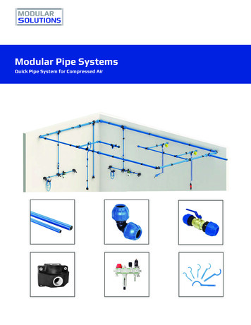
When a pipe enters a building, freezing conditions of the pipe may permeate pastthe exterior wall of the building. To prevent the pipes from freezing, the heating cableshould extend along the pipe at least 12” into the building.12”SECTION 11.71 Pipes Entering a BuildingSpecial Installation Considerations1. 7 Special Installation ConsiderationsHeating CablePipeGlass Cloth Tape1.7FIGURE 1.71: Pipes Entering a Buildingpre-installation1.72 Pipes Entering UndergroundWhen a pipe enters the ground, freezing conditions of the pipe will permeate belowground to the frost line depth. To prevent the pipes from freezing, create a loop with theheating cable and extend to the frost line depth for your geographic region. Terminatethe end of the heating cable above the normal water line with a heat shrink end seal.EndSealWater LineHeatingCablePipeFrost DepthFIGURE 1.72: Pipes Entering UndergroundNuheat Pipe Freeze Protection System Installation Guide13
SECTION 11. 8 Pre-Installation ChecksPlan installation layout[ ] It is VERY IMPORTANT to plan the installation before securing any part ofthe heating cable system to the roof and / or gutter system. Note the locationof the controls and / or junction boxes.pre-installationDesign Notes[ ] Review any design notes provided by Nuheat’s Customer Care Team. Notespecific installation instructions and plan which direction / sequence thecable will be installed.1.8Circuit Lengths[ ] Observe the maximum circuit lengths of the cable ( Appendix 3 on page31 ) and do not exceed these limits during the installation. Exceeding themaximum circuit lengths will result in breaker trips which will prevent theheating cable from turning on in freezing conditions.Pre-installation checksAccessories[ ] Ensure you have all the necessary connection / splice kits and accessories.Visually inspect heating cable[ ] Unpack and perform visual inspection of the entire heating cable for anyvisible damage. If the heating cable is damaged, do not begin installation.Contact Nuheat Customer Care Team at 1.800.778.WARM ( 9276 ).Insulation Resistance and continuity tests[ ] Perform insulation resistance and continuity tests. Refer to testingprocedures on page 10 of this manual.Confirm wattage[ ] Confirm wattage output of cable is adequate for your design and installationconditions. The wattage output of the heating cable should exceed the heatloss per foot value indicated in Appendix 1 & 2 (page 29-30).Confirm voltage[ ] Ensure supply voltage matches voltage rating on heating cable.14Nuheat Pipe Freeze Protection System Installation Guide
2.1Installationoverview182.2 Cable Layout192.21Unspooling the Cable . 192.22Incorporating Pipe Features . 192.23Power Connections, Splices and End Seals . 202.3 Securing the Cable212.31Securing Heating Cable to Pipe . 212.32Securing Heating Cable to Pipe Hanger . 222.33Securing Heating Cable to Pipe Flange . 222.34Securing Heating Cable to Pipe Supports . 232.35Securing Heating Cable to Pipe Valves and Gauges . 232.4Power Connection2.5 Thermostat2.62424Insulation252.61Install Insulation . 252.62Install Warning Labels . 252.63Insulation & Resistance Tests . 252.7 post-installation checks26Nuheat Pipe Freeze Protection System Installation GuideSECTION 2SECTION 2
2.1 Installation: Overview2.11 Pipe Freeze Protection Installation OverviewSECTION 2! For plastic pipes, apply aluminum tape along the length of thepipe before securing the heating cable to the pipe. The heatingcable should be secured on top of the aluminum tape.1. Loosely run the cable along the length of the pipe.2. Attach the heating cable to the pipe and pipe features using glass cloth tape.3. Install splices, end seals and power connections.INSTALLATION4. Install thermostat sensor onto the pipe.5. Install pipe insulation and warning labels/stickers.Glass Cloth Tape2.1overview12”Heating CableWarning LabelPipe InsulationFIGURE 2 .1: Pipe Freeze Protection Installation Overview16Nuheat Pipe Freeze Protection System Installation Guide
2.2 Installation: Cable layoutPlace spool of cable near end of pipe to be traced. Cable payout mechanism shouldallow cable to unspool smoothly without excessive pulling or tugging. Loosely stringcable along entire length of pipe.2.22 Incorporating Pipe FeaturesMetal features commonly attached to pipes are heat sinks that will draw heat from theheating cable. Extra cable is required to heat pipe features and/or navigate obstacles.SECTION 22.21 Unspooling the VALVESINSTALLATIONPIPEDIAMETER(INCHES)cable layoutThe table below shows how many feet of heating cable should be used to heat tracecommon pipe features:FIGURE 2 .22a: Heat Cable Length Requirements for Common Pipe FeaturesNuheat Pipe Freeze Protection System Installation Guide17
2.2 Installation: cable layoutIf the branch/tee pipe(s) are less than 20ft long, it is easier and more economical toloop/double-back the heating cable. This eliminates the labor and cost of installing atee splice kit.SECTION 2Glass Cloth TapeHeating CablePipeLooped-back CableINSTALLATIONFIGURE 2.22b: Loop/Double-back Method2.23 power connections, splices and end seals2.2Any splices or power connections will require extra heating cable. Refer to the list belowfor heating cable allowances required to complete common heat shrink connections.cable layoutPower ConnectionAllow 6” (inches) of heating cable at the location of the connection.Splice (regular splice or tee splice)Allow 12” (inches) of heating cable at the location of the connection fromeach cable run that will be spliced together.18Nuheat Pipe Freeze Protection System Installation Guide
2.3 Installation: Securing the CableFor plastic pipes, apply aluminum tape along the length of the pipe before securingthe heating cable to the pipe. The heating cable should be secured on top of thealuminum tape.Starting at the end and working towards the cable payout mechanism, begin fasteningthe heating cable to the pipe using glass cloth tape. Plastic cable ties may also beused to secure heating cable to pipe, but must only be hand-tightened.securing the cable! Do not use vinyl electrical tape to secure heating cable to pipe.SECTION 22.31 securing heating cable to pipeInsulation12”PipeGlass Cloth TapeHeating Cable2.3FIGURE 2.31a: Heating Cable Secured to Pipe90 45 90 45 Runs of One Heating CableINSTALLATIONWhenever possible, the heating cable should be positioned on the lower section of thepipe typically at the 4 o’clock and/or 8 o’clock positions.45 Runs of Two Heating CableFIGURE 2.32b: Heating Cable Secured at 4 and 8 o’clock position!Install splice or tee splice connections only. Do not make powerconnections at this point of the installation.Nuheat Pipe Freeze Protection System Installation Guide19
2.3 Installation: Securing the Cable2.32 Securing heating cable to Pipe HangerPipe HangerUnder InsulationSECTION 2Pipe HangerPipe HangerOver InsulationInsulationInsulationPipe HangerGlassClothTapeGlassClothTapeHeating CableHeating CableINSTALLATIONFIGURE 2.32: Securing Heating Cable to Pipe Hanger!Install splice or tee-splice connections only. Do not make powerconnection at this point of the installation.2.3securing the cable2.33 Securing heating cable to Pipe FlangeHeating CableFlangeInsulationGlass Cloth TapeFIGURE 2.33: Securing Heating Cable to Pipe Flange!20Install splice or tee-splice connections only. Do not make powerconnection at this point of the installation.Nuheat Pipe Freeze Protection System Installation Guide
2.3 Installation: securing the cable2.34 Securing heating cable to Pipe SupportsHeating CableSECTION 2Glass Cloth Tapesecuring the cablePipe SupportInsulationFIGURE 2.34: Securing Heating Cable to Pipe Supports!Install splice or tee-splice connections only. Do not make powerconnection at this point of the installation.2.32.35 Securing heating cable to Pipe valves and gaugesValveHeating CableINSTALLATIONInsulationGlass Cloth TapeFIGURE 2.35: Securing Heating Cable to Pipe Valves and Gauges!Install splice or tee-splice connections only. Do not make powerconnection at this point of the installation.Nuheat Pipe Freeze Protection System Installation Guide21
2.4 Installation: Power Connection2.41 Power connectionSECTION 2After all the cable runs are secured to the piping, confirm that the length of the cable(s)on each circuit does not exceed the maximum circuit length in Appendix 3 (page 31)by performing a Circuit Length Verification test (page 11).Install heat shrink end seals and power connections. Refer to the installationinstructions that accompany the heat shrink kit.Perform insulation resistance and continuity tests. Refer to testing procedures on page10 of this guide.INSTALLATION2.5 Installation: Thermostat2.51 Install Probe2.4power connectionInstall the thermostat as per installation instructions. Place the thermostat probe ontothe pipe. The sensing bulb should be placed on the pipe at least 90 around thecircumference from the heating cable or at least 50mm from the heating cable.! Sensing line should exit through lower portion of thermal insulation.2.52 Install Thermostat/Follow instructions provided with thermostat for proper thermostat wiring. Ensurecontroller or contactor is appropriate for electrical load. For technical support, contactthe Nuheat Customer Care Team at 1.800.778.9276.2.5install thermostat22Nuheat Pipe Freeze Protection System Installation Guide
2.6 Installation: Insulation2.61 Install Insulation! Do not use staples to seal the insulation as staples can damagethe heating cable. Use tape or adhesive to ensure that theinsulation seam remains sealed.2.62 Install Warning LabelsSECTION 2Install the pipe insulation suitable for the specific application. If the pipe is outdoors, amoisture-proof weather barrier surrounding the thermal insulation must be installed.INSTALLATION2.6install InsulationWhile installing the insulation, mark the location of the splices, tees, and end seals onthe outside of the insulation or weather barrier using the labels/stickers provided inthe connection kits. Electrical code also requires “Electric Heat Tracing” warning labelsto be applied over top of the insulation or weather barrier at regular intervals (10-footintervals recommended).Nuheat Pipe Freeze Protection System Installation Guide23
2 . 7 Post-Installation ChecksSECTION 2Warning labels[ ] Ensure locations of splices, tees, and end seals are clearly marked.Electrical code requires “Electric Heat Tracing” warning labels to be appliedover top of the insulation or weather barrier at regular intervals [10’ (foot)intervals recommended].Insulation Resistance and continuity tests[ ] Perform insulation resistance and continuity tests. Refer to testingprocedures on page 10 of this manual.INSTALLATIONCircuit Lengths verification tests[ ] Perform circuit length verification tests on each circuit of heating cable.Refer to testing procedures on page 11 of this manual.Observe the maximum circuit lengths of the cable ( Appendix 1 on page 32 )and do not exceed this limit during the installation. Exceeding the maximumcircuit lengths will result in breaker trips which will prevent the heating cablefrom turning on in freezing conditions.2.7Post installation checks24Nuheat Pipe Freeze Protection System Installation Guide
SECTION 3Electric connections &controls3.1 Typical wiring diagrams283.11Single Circuit Control . 283.12Group Circuit Control . 283.2repairs and maintenance283.3 Appendix 1: Heat Loss For Metal Pipes29Appendix 2: Heat loss for plastic pipes30Appendix 3: maximum circuit length31Nuheat Pipe Freeze Protection System Installation Guide
Electrical connections & controls3.1 Typical Wiring Diagram3.11 Single Circuit Control1-Pole GFEP BreakerHeating CableØGround1 Ø Supply1Temperature ControlGFIGURE 3.11: Single Circuit ControlSECTION 33.12 group ControlHeating CableTemperatureControl1-Pole GFEP BreakerØCNع1 Ø SupplyØس ²Ground3-PoleMainBreaker3-phase4-wire supply(WYE)3.1NG (Type 3)typical wiring diagramFIGURE 3.12: Group Control3.2 Repairs and Maintenance3.21 Repairs & MaintenanceIf any part of the cable becomes damaged at any time, please contact NuheatCustomer Care Team immediately at 1.800.778.WARM (9276).Testing and visual inspections should be performed after any type of maintenance orrepair including but not limited to cleaning, re-insulating, and installation/addition ofpipe segments or features.Test and ensure pipe freeze protection system is functioning properly prior to eachwinter season.26Nuheat Pipe Freeze Protection System Installation Guide
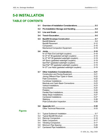
F N 3InsulationThicknessAppendix 1: Heat Loss for metal pipesMinimum AmbientTemperature3.3PipeDiameterElectrical connections & controls3.3 Appendix 1: Heat Loss for Metal PipesFor pipe diameters greater than 10” (inch), contact Nuheat at 1.800.778.WARM ( 9276 )Nuheat Pipe Freeze Protection System Installation Guide27
Electrical connections & controls3.3 Appendix 2: Heat Loss for plastic PipesPipeDiameterMinimum AmbientTemperatureInsulationThickness F0-10-20-40 66.88.92.83
6 Nuheat Pipe Freeze Protection System Installation Guide sec TI on 1 IMPORTANT INSTALLATION GUIDELINES Do not energize the cable(s) before installation is complete. Ensure bus wires of the same cable are separated. Bus wires will short if they contact each other when energized. Cable ends must be terminated with Nuheat end seals.