Transcription
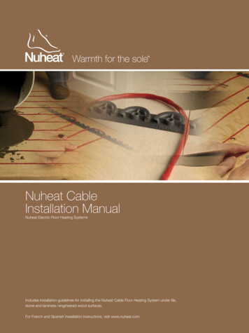
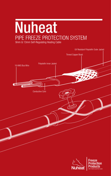
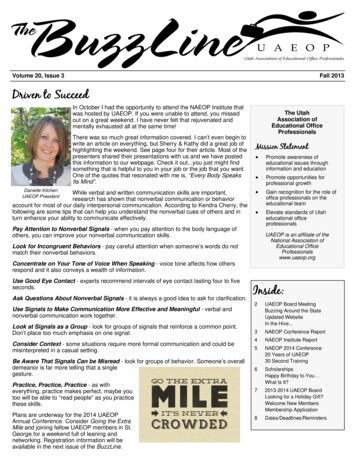
NuheatWEATHER-READYROOF & GUTTER DE - ICING SYSTEM 13mm Self-Regulating Heating CableUV Resistant Polyolefin Outer JacketTinned Copper BraidPolyolefin Inner JacketFire Resistant Conductive Core16 AWG Bus Wires
Nuheat Industries Limited 2014 Nuheat Industries Limited. All rights reserved.The entire contents of this manual, including but not limited to text, images, and the selection andarrangement of information (collectively the “Materials”), are protected by copyright and otherintellectual property laws under the laws of Canada and other countries.ATTENTION: The installation of this heating product shall be in accordance with themanufacturer’s instructions and in accordance with the Canadian ElectricalCode Part 1 or the National Electrical Code (US) whichever is applicable. This equipment shall be installed only by qualified personnel who are familiarwith the construction and operation of the apparatus and risks involved. Caution should be taken to guard against risk of electric shock, fire andbodily injury during the installation of this equipment. Indicate on the electrical panel which circuit is used for the Nuheat FreezeProtection Product.Nuheat Weather-Ready Roof & Gutter De-Icing System Installation Guide
Section 1: Pre-Installation1.1Important Installation Guidelines . 61.2Before You Start . 71.3System Components . 81.4Insulation & Continuity Tests . 121.5Insulation Resistance Table . 141.6Pre-Installation Checklist . 15Section 2: Installation2.1Gutters . 172.2Downspouts . 182.3Roof . 212.4Post-Installation Checklist . 26Section 3: Electrical Connections & Controls3.1Electrical Connections . 283.2Typical Wiring Diagram . 293.3Control Options . 303.4Repairs and Maintenance . 303.5Appendix 1 . 31Nuheat Weather-Ready Roof & Gutter De-Icing System Installation Guidetable of contentsTable of Contents
Pre-installation1.1Important installation guidelines61.2before you start71.21Tools. 71.22Materials . 71.3 System Components81.31Roof & Gutter De-icing System Overview . 81.32Roof & Gutter De-icing System . 91.33Power Connections, Splices, End Seals . 91.34Snow Controller / Sensor . 91.35Roof Clips . 101.36Downspout Hangers . 111.4Insulation & Continuity Tests121.41Insulation Test . 131.42Continuity Test . 131.43Frequency of Testing . 131.44Circuit Length Verification Table . 131.5Insulation Resistance Table141.6Pre-Installation CheckLIST15Nuheat Weather-Ready Roof & Gutter De-Icing System Installation GuideSECTION 1SECTION 1
SECTION 11.1 pre-INSTALLATIOn 1.1Important Installation guidelines Important Installation GuidelinesDo not energize the heating cable(s) before installation is complete.Ensure bus wires are separated. Bus wires will short if in contact whencables are powered.Cable ends must be terminated with Nuheat end seals. Bus wires cannot beleft exposed.Bus wires and cable terminations should be kept dry before, during, andafter installation.Ensure drip loops are made to prevent water from trailing into any electricalequipment, junction boxes, or controls.Be careful not to break bus wire strands when isolating bus wires during spliceconnections. Damaged bus wires can overheat or may cause a short circuit.Only use Nuheat connection components to make splices and/or endterminations. Nuheat connection components are certified and approved foruse with Nuheat self-regulating cables.Do not use epoxies or acid-curing silicones to attach roof clips to roof. Epoxiesor acid-curing silicones are generally not suitable for exterior roof and gutterapplications. Consult a roofing contractor in your area for recommendationson proper adhesives for roof material and environmental conditions.Observe the maximum circuit lengths of the cable ( Appendix 1 on page 31)and do not exceed this limit during the installation. Exceeding the maximumcircuit lengths will result in breaker trips which will prevent the heating cablefrom turning on in freezing conditions.Conduct insulation and resistance tests before, during, and after installation.Refer to testing procedures on page 12 of this guide.Testing and visual inspections of the heating cable should be performedafter any type of roof maintenance or repair including but notlimited to roof / gutter / downspout repair, manual snow removal, andinstallation / addition of roof features.Ensure gutters and downspouts are free of leaves and other debris prior toeach winter season.Materials used for the housing (ie. junction boxes), support or on which thecables are installed shall be grounded in accordance with CSA and UL standard.All installations must be in compliance with the following electrical codes:o Articles 426 and 500 of the NEC (National Electrical Code)o Sections 62 and 18 of the CEC (Canadian Electrical Code)NUHEAT INDUSTRIES AND NEC REQUIRE 30 mA EQUIPMENT GROUNDFAULT PROTECTION ON EACH HEATING CABLE BRANCH CIRCUIT.6Nuheat Weather-Ready Roof & Gutter De-Icing System Installation Guide
SECTION 11. 2 Before You StartThe following tools /materials are required for the Nuheat Weather-Ready Roof & Gutter De-icing System installation:1000Vdc megohmmeterMultimeterMethod to payout / unreel the heating cableCutting pliersTools to secure roof clips ( if installing heating cable on roof )o Hammer / Drills ( if using screws / nails to secure the roof clips )ORo Caulking gun ( if using adhesive to secure the roof clips )1.2 before you start1.21 Tools pre-INSTALLATIOn1.22 MaterialsMaterials to secure the Nuheat roof clips to the roof and / or gutter( based on the application and installation method ):o Suitable adhesive / sealanto Screws / NailsMaterials needed for electrical connectionso Nuheat approved connection kitso Junction boxeso Suitable conduit for various connections» Between breaker panel and junction boxes» Between junction boxes and controlUV cable tieso Only required if heating cable installed on BOTH roof and guttersNuheat Weather-Ready Roof & Gutter De-Icing System Installation Guide7
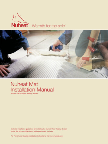
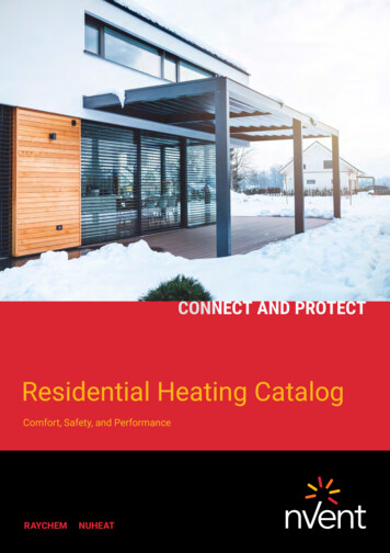
SECTION 11. system3components1.31 Roof & Gutter De-icing System Overviewpre-INSTALLATIOnValley1.3System ComponentsRoof clipEnd sealHeatingcableGutterJunctionboxDownspoutFIGURE 1.31: Roof & Gutter De-icing SystemThe Nuheat Weather-Ready Roof & Gutter De-icing System creates / maintains drainpaths to help remove melt water from roof and gutter systems. This will prevent icedams and ice build-up that can cause extensive damage to roof and gutter systems.Nuheat Roof & Gutter De-icing System is compatible with: 8Standard gutter / downspout materialso Metalo Plastico Wood Standard roof materialso Shake / Shingleo Rubber / Taro Woodo Metalo PlasticNuheat Weather-Ready Roof & Gutter De-Icing System Installation Guide
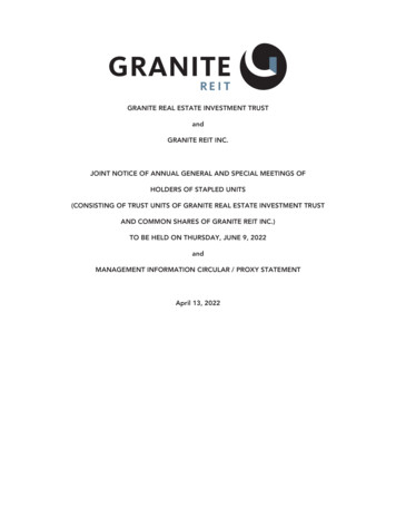
SECTION 11. system3components1.32 Roof & Gutter de-icing systemSystem ComponentsNuheat self-regulating heating cables are installed inside the gutters, downspoutsand / or installed on roofs.UV Resistant Polyolefin Outer JacketPolyolefin Inner JacketTinned Copper Braid1.3Conductive Corepre-INSTALLATIOn16 AWG Bus WireFIGURE 1.32: Roof & Gutter Self-Regulating Heating Cable1.33 Power Connections, Splices, End SealsSpecific kits are required to connect heating cables to power, splicing / splitting toextend heating cable into downspouts, and sealing cable end(s).1.34 Snow Controller or ThermostatsSnow controllers or thermostats control when heating cables turn on / off. There areseveral snow controller and thermostat options with varying levels of customization.More information on snow controllers and thermostats can be found on page 30.Nuheat Weather-Ready Roof & Gutter De-Icing System Installation Guide9
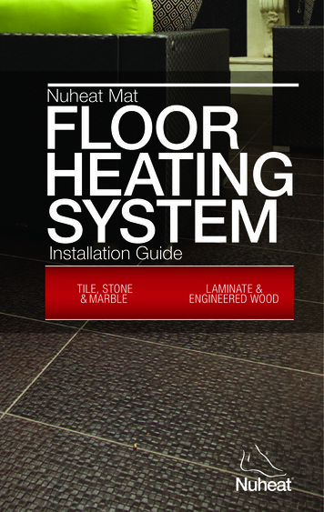
SECTION 11. system3components1.35 Roof Clipspre-INSTALLATIOnThe heating cable can be attached to a roof using Nuheat roof clips. Secure Nuheat roofclips to roof using screws, nails or adhesives. If screws or nails are used, weatherproofsealant must cover screws or nail holes to prevent water ingress.Roof clipsCable ties1.3Roof clipsHeating CableSystem ComponentsFIGURE 1.35a: Roof ClipsNuheat roof clips can also be used as spacers inside gutters when multiple runs ofcable are used. Secure roof clips to gutter base using weather resistant adhesive.Roof clipsHeating CableFIGURE 1.35b: Roof Clips10Nuheat Weather-Ready Roof & Gutter De-Icing System Installation Guide
Nuheat downspout hangers are required to prevent damage to heating cable as itenters / exits the downspout. Downspout hangers can also be used as spacers insidethe gutters when multiple runs of heating cable are used.SECTION 11.36 Downspout HangersSystem Components1. system3components! Downspout hangers do not need to be secured to gutters.1.3When entering / exiting a downspout, bend downspout hanger to 90 and place overgutter / downspout transition. Run heating cable overtop of hanger and secure usingUV resistent cable ble tiesFIGURE 1.36a: Downspout HangerWhen using downspout hangers as spacers in wider gutters, place the hangers at thebase of the gutter and angle across gutter width. Run heating cable overtop of hangerand secure to hanger using UV resistant cable ties.HeatingcableDownspouthangerFIGURE 1.36b: Downspout Hangers as SpacersNuheat Weather-Ready Roof & Gutter De-Icing System Installation Guide11
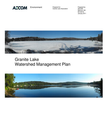
SECTION 11. 4 Insulation & Continuity TestsInsulation resistance tests must be performed on each circuit before,during and after installation of the Nuheat Roof & Gutter De-IcingSystem. Insulation resistance readings must be recorded in the tablesin Section 1.5pre-INSTALLATIOnBefore performing any tests, disconnect all electrical components to the heating cableincluding power, thermostats, and contactors. The two bus wires and metal groundbraid needs to be separated prior to conducting any tests.1.4To separate the bus wires and ground braid:1. Lightly score around and down the outer jacket 3” from the end of the heatingcable. Bend heating cable to break jacket at score; peel off outer jacket.2. Push back braid to loosen. Spread apart braid, bend the heating cable andwork it through the opening in the braid.3. Position braid on one side of the cable and twist into a pigtail.4. Lightly score around and down the inner jacket 1.5” from the end of theheating cable and remove.5. Cut down the center of the conductive core and trim away ½” of theconductive core from the tip of the cable exposing the bus wires.insulation & continuity tESTUV Resistant Polyolefin Outer JacketTinned Copper BraidConductive Core1.5”1”Polyolefin Inner Jacket0.5”Bus WiresFIGURE 1.4: Separating Heating Cable Bus Wires12Nuheat Weather-Ready Roof & Gutter De-Icing System Installation Guide
SECTION 11.41 Insulation Resistance Test1. Set the megohmmeter voltage to 0 Vdc.2. Connect the negative alligator clip to the metallic braid of the heating cable.3. Connect the positive alligator clip to the both heating cable bus wires.4. Turn on the megohmmeter and set the voltage to 500 Vdc.5. Apply voltage for one (1) minute.6. Check the resistance reading.7. Confirm that the resistance is greater than 20 megaohms.8. Record insulation resistance reading in table in Section 1.5.9. Repeat step 4-7 at 1000 Vdc.10. Confirm that the resistance value is within /- 10% of each other regardlessof the voltage applied.11. Record insulation resistance reading in table in Section 1.5.Insulation & continuity Test1. 4 Insulation & Continuity Testspre-INSTALLATIOn1.41.42 Continuity Test1. Set the multimeter to measure resistance.2. Twist the two bus wires together at one end of the cable.3. At the other end of the cable, connect the positive alligator clip to one of thebus wires and connect the negative alligator clip to the other bus wire.4. Confirm the resistance reading is less than 3 ohms. Resistance readings of1000 ohms or greater generally indicate damage to the bus wire or improperlyinstalled connection kits.1.43 Frequency of TestingInsulation resistance and continuity tests should be performed: Before installing the heating cable After installing connection kits (refer to connection kits instructions) Before installing the thermal insulation Before initial start-up (commissioning)Testing should also be included as part of regular system inspections, as well as afterany maintenance or repair work.1.44 Circuit Length Verification Test1. Set megohmeter to measure capacitanceand set meter to 200 nF range.2. Connect positive alligator clip to braid wire.3. Connect negative alligator clip to bothbus wires.4. Multiply this reading by capacitancefactor indicated on the right to determinetotal circuit length (in eat Weather-Ready Roof & Gutter De-Icing System Installation Guide13
SECTION 11. 5 Insulation Resistance TableIf the reading on the insulation resistance test does not pass the requirements at anypoint of the installation, halt installation immediately and contact Nuheat TechnicalServices at 1.800.778.WARM (9276).pre-INSTALLATIOnRecord heating cable insulation resistance test in the table below and leave with theend user for warranty purposes:INSULATIONRESISTANCERun 1BeforeInstallingheating cableAfterBefore InitialInstallingstart-upConnection kits (commissioning)@ 500 Vdc1.5@ 1000VdcInsulation Resistance TableRun 2@ 500 Vdc@ 1000VdcRun 3@ 500 Vdc@ 1000VdcRun 4@ 500 Vdc@ 1000VdcRun 5@ 500 Vdc@ 1000VdcFailure to record insulation resistance tests in the above table will voidthe Nuheat Weather-Ready Roof & Gutter De-Icing System warranty.The Nuheat standard limited warranty for freeze protection products applies to PipeFreeze Protection and Roof & Gutter De-icing products.Nuheat self-regulating cable is eligible for an additional seven (7) year warranty (totalperiod of ten [10 ] years) provided the online warranty form (available at nuheat.com)is fully completed and registered within thirty ( 30 ) days from the date of installation.14Nuheat Weather-Ready Roof & Gutter De-Icing System Installation Guide
[ ] It is VERY IMPORTANT to plan the installation before securing any part of theheating cable system to the roof and / or gutter system. Note the location ofthe controls and / or junction boxes.SECTION 1Plan installation layoutPre-installation checks1. 6 Pre-Installation ChecklistDesign Notes[ ] Review any design notes provided by Nuheat’s Customer Care Team. Notespecific installation instructions and plan which direction / sequence thecable will be installed.Circuit Lengthspre-INSTALLATIOn1.6[ ] Observe the maximum circuit lengths of the cable ( Appendix 1; page 31 ) anddo not exceed these limits during the installation. Exceeding the maximumcircuit lengths will result in breaker trips which will prevent the heating cablefrom turning on when snow/ice is present.Accessories[ ] Ensure you have all the necessary connection / splice kits and accessoriesincluding roof clips and downspout hangers ( if applicable ).Visually inspect heating cable[ ] Unpack and perform visual inspection of the entire heating cable for anyvisible damage. If the heating cable is damaged, do not begin installation.Contact Nuheat Customer Care Team at 1.800.778.WARM ( 9276 ).Insulation Resistance and continuity tests[ ] Perform insulation resistance and continuity tests. Refer to testing procedureson page 12 of this manual.Nuheat Weather-Ready Roof & Gutter De-Icing System Installation Guide15
SECTION 2installation2.1 Gutters172.11Single Run of Heating Cable . 172.12Double Run of Heating Cable .17SECTION 22.2 Downspouts182.21Entering Downspout . 182.22Entering Downspout: Tee Splice Method . 192.23Exiting Downspout: Above Ground . 192.24Exiting Downspout: Below Ground . 20INSTALLATION2.3 Roofs2.312.322.332.342.3521Sloped Roof . 21Heating Roof Drains . 22Flat Roof . 23Metal and Standing Seam . 24Valleys and Wall Intersections . 252.4 post-installation checks1626Nuheat Weather-Ready Roof & Gutter De-Icing System Installation Guide
2.1 Installation: GuttersLay heating cable at base of gutter to create / maintain drain paths for melt water.Gutters2.11 Single Run of Heating CableSECTION 2Install heating cable along gutter base to prevent ice dams and ice build-up inside thegutter system. Ice build-up can lead to icicle formations which may damage the guttersystem, as well as pose a safety risk ( i.e. potential falling icicles ).Heating cable2.1GutterINSTALLATIONFIGURE 2 .11: Single Run in Gutter2.12 Double Run of heating cableFor gutters wider than 6” ( 150mm ), use two runs of heating cable inside gutter. Toensure optimal cable spacing of 4” - 6” ( 100 - 150mm ), secure heating cable to Nuheatdownspout hangers or roof clips.Downspout hangerRoof clipFIGURE 2 .12: Double Run in GutterNuheat Weather-Ready Roof & Gutter De-Icing System Installation Guide17
2.2 Installation: DownspoutsInstall heating cable inside all downspouts to prevent ice dams from forming within thegutter system. Heating downspouts will create drain paths for melt water to exit thegutter system and reduce the risk of ice and snow damage.SECTION 22.21 entering DownspoutInstall heating cable inside the downspouts to ensure ice does not build-up andprevent melt water from exiting the gutter system.! Use downspout hangers to protect cable from sharp edges orprotrusions in the gutter.INSTALLATIONHeating cableCable tiesDownspout hangerGutter2.2DownspoutDownspoutsFIGURE 2 .21: Heating Cable Entering DownspoutAlternatively, use loop-back method to extend heating cable into downspout. Createa loop in a single run of heating cable. Extend loop into downspout until it reachesdownspout exit.! Use downspout hangers to protect cable from sharp edges orprotrusions in gutter.GutterCable tiesDownspout hangerHeating cableCable tiesDownspout hangerHeating cableFIGURE 2.22: Loop-back Method18Nuheat Weather-Ready Roof & Gutter De-Icing System Installation Guide
2.2 Installation: Downspouts2.22 Entering downspout: Tee Splice MethodInstall connection components according to installation instructions included inconnection kits. Extend a single heating cable run into downspout until it reachesdownspout exit.! Use downspout hangers to protect cable from sharp edges orprotrusions in the gutter.Downspouts! Test continuity of each cable run before installing heat shrinks.SECTION 2If necessary, use a Nuheat splice / tee kit to create a tee-splice at entrance to downspout.Tee - spliceHeating cableCable ties2.2Downspout HangerINSTALLATIONFIGURE 2 .22: Tee - Splice Method2.23 Exiting Downspout: Above GroundIf a single run of heating cable is used in the downspout, terminate cable with end seal.Create a drip loop extending 1” ( 25mm ) past downspout exit. Secure end seal 12”( 300mm ) up from downspout exit.! Ensure all cable protruding past lower opening of downspout isnot susceptible to damage.End sealCable tiesGutter12”1”FIGURE 2.23: Exiting Downspout Above GroundNuheat Weather-Ready Roof & Gutter De-Icing System Installation Guide19
2.2 Installation: Downspouts2.24 Exiting Downspout: Below GroundSECTION 2Determine the frost line depth based on the geographic region. If using the loop-backmethod to extend the heating cable into downspout, ensure the loop of heating cableat the bottom of the downspout extends below the frost depth.If a single run of heating cable is extended into the downspout, create a drip loop andsecure the end seal to the heating cable prior to inserting the cable into downspout.! Ensure all cable protruding past downspout opening is notsusceptible to damage.INSTALLATIONGutterEnd sealCable ties2.2Downspouts12”Frost lineHeatingcableFIGURE 2.24: Exiting Downspout Below Ground20Nuheat Weather-Ready Roof & Gutter De-Icing System Installation Guide
installation: Roof2.3On sloped roofs, the heating cable is generally installed in a zig-zag pattern above theun-insulated overhang section of the roof.2.31 Sloped RoofAttach heating cable to roof using roof clips in a triangular pattern along roof edge. Seefigure 2.31.SECTION 2Ice dams may form at roof edge because the section of roof above overhang is uninsulated. Install heating cable on this section of the roof to create / maintain drainpaths for melt water to flow off the roof and into gutter system.2.3 Roof! Ensure top of triangle is approximately 6” ( 150mm ) past theexterior wall.! Ensure distance between triangles is approximately 24” (600mm).INSTALLATIONExtend drip loops past roof edge into gutter. If heating cable is installed along gutterbase, connect drip loop to gutter run using UV-resistant cable ties. This will ensure themelt water has a continuous path from roof to gutter.Roof clip6”Cable ties24”Heating cableGutterExterior wallFIGURE 2.31: Sloped RoofNuheat Weather-Ready Roof & Gutter De-Icing System Installation Guide21
2.3installation: Roof2.32 Heating Roof DrainsSECTION 2To maintain proper roof drainage and prevent ice damage, install heating cable fromroof edge to roof drain. Extend heating cable loop into roof drain, ensuring cablereaches 12” ( 300mm ) into heated zone below roof.Roof drainINSTALLATIONHeating cable12”2.3RoofFIGURE 2.32: Roof Drains22Nuheat Weather-Ready Roof & Gutter De-Icing System Installation Guide
2.3installation: RoofFlat roofs are usually pitched to direct water to roof drains, downspouts or scuppers.Install heating cable around the perimeter and along the melt water path to roof drains,downspouts or scuppers. Use roof clips to secure the heating cable.Junction boxRoof clipHeating cableSECTION 22.33 Flat Roof2.3ROOFRoof drainINSTALLATIONEnd sealFIGURE 2.33a: Flat Roof to DrainJunction boxRoof clipHeating cableEnd sealScuppersFIGURE 2.33b: Flat Roof to ScuppersNuheat Weather-Ready Roof & Gutter De-Icing System Installation Guide23
2.3installation: Roof2.34 Metal and Standing seamSECTION 2Metal/Standing seam roofs are most common in commercial or industrial applications.Typical seam distance varies between 18” (460mm) to 24” ( 610mm). Using roofclips, attach heating cable to roof along seam. Run heating cable over seam andreverse direction. Extend heating cable past roof edge and into gutter. Lay heatingcable horizontally along gutter base. Heating cable should be installed alongevery other seam.! Ensure loop of heating cable extends approximately 6” ( 150mm )up past exterior wall.INSTALLATION! Distance between cable runs should not exceed 24” ( 610mm).2.3RoofRoof clipSeam6”Cable tiesHeating cableEnd sealGutterFIGURE 2.34: Metal & Standing Seam Roof24Nuheat Weather-Ready Roof & Gutter De-Icing System Installation Guide
2.3 Installation: RoofWhen sloped sections of roof meet or are intersected by a wall, the roof forms a valleyor wall intersection. In both instances, run the heating cable two-thirds up the valleyor wall intersection and back down to maintain drain paths.¹ ³ValleySECTION 22.35 Valleys and Wall Intersections2.3Roof² ³INSTALLATIONHeating cableRoof clipsFIGURE 2.35a: Sloped Roof Valley¹ ³² ³4”6”-32””Wall intersectionRoof clipsHeating cableGutterFIGURE 2.35b: Wall IntersectionsNuheat Weather-Ready Roof & Gutter De-Icing System Installation Guide25
2 . 4 Post-Installation ChecklistDownspout hangers[ ] Use downspout hangers to ensure heating cable is protected from potentialmechanical damage.SECTION 2Insulation Resistance tests[ ] Perform insulation resistance tests. Refer to testing procedures on page 12of this manual.Circuit LengthsINSTALLATION[ ] Observe the maximum circuit lengths of the cable ( Appendix 1 on page 31)and do not exceed this limit during the installation. Exceeding the maximumcircuit lengths will result in breaker trips which will prevent the heating cablefrom turning on when snow/ice is present.2.4Post-installation checks26Nuheat Weather-Ready Roof & Gutter De-Icing System Installation Guide
3.1Electrical connections& controlsElectrical connections & controlsSECTION 3electrical connections283.11Power Connection . 283.12Drip Loop . 283.3control options303.31Automatic Snow Controllers . 303.32Slab Sensing Thermostat . 303.33Manual On / Off Control . 303.4repairs AND maintenance3.5 Appendix 13031Nuheat Weather-Ready Roof & Gutter De-Icing System Installation GuideSECTION 33.2 Typical wiring diagrams293.21Single Circuit Control . 293.22Group Circuit Control . 2927
Electrical connections & controls3.1 Electrical Connections3.11 Power ConnectionAfter heating cable and related accessories are installed, install power connectioncomponents according to installation instructions included in connection components.Visually inspect the entire circuit and perform insulation resistance tests for eachcircuit before connecting heating cable to power.3.12 Drip LoopSECTION 3Create drip loops to prevent water from trailing into any electrical equipment, junctionboxes, or controls.Heating cableJunction box3.1Drip loopelectrical connectionsFIGURE 3.12: Drip Loop28Nuheat Weather-Ready Roof & Gutter De-Icing System Installation Guide
Electrical connections & controls3.2 Typical Wiring Diagram3.21 Single Circuit COntrolTemperature Controller1-Pole GFEP BreakerØ1 Ø Supply3.22 Group Circuit COntrolTemperature ControllerØ1 Ø SupplyNعزس3.2Contactortypical wiring diagramC3-Phase 4-Wire Supply1-Pole GFEP BreakerSECTION 3NHeating CableNGNUHEAT INDUSTRIES AND NEC REQUIRE 30 mA EQUIPMENT GROUNDFAULT PROTECTION ON EACH HEATING CABLE BRANCH CIRCUIT.Nuheat Weather-Ready Roof & Gutter De-Icing System Installation Guide29
Electrical connections & controls3.3 Control OptionsThere are several options available to control the Nuheat Roof and Gutter De-icingCables. Consult the electrical contractor to determine the most suitable option.Selecting the proper control option will limit the power consumption of the de-icingsystem by turning on the heating cables only when it is needed.3.31 Automatic Snow Controller Activates system when precipitation AND low temperatures are detectedSystem remains “ON” once precipitation or low temperature have ceased,allowing the surface to completely dry, preventing the formation of surface iceWhen combined with a slab-sensing thermostat, the system will de-energizeonce the slab has reached the preset or user-defined temperature setpointSECTION 33.32 Ambient Sensing Thermostat Turns on the heating cable when the ambient temperature drops below apreset or user-defined temperature (usually set at freezing point)Not as energy efficient as ambient temperature may be below freezing butno precipitation/snowfall is present3.33.33 Manual On / Off ControlControl options / 3.4 Low initial costRecommended only for small areasRequires manual monitoringProne to be left on accidentallyInstall the controls as per installation instructions that accompanycontrol unit. Ensure controller or contactor being used is appropriatefor electrical load.Repairs and maintenance3.4repairs and MaintenanceIf any part of the cable becomes damaged at any time, please contact NuheatCustomer Care Team immediately at 1.800.778.WARM (9276).Perform visual inspection, and insulation and continuity tests annually before eachwinter season. Ensure control system is functioning before each winter season.30Nuheat Weather-Ready Roof & Gutter De-Icing System Installation Guide
Electrical connections & controls3.5 Appendix 1Maximum Circuit Lengths120V240V C15A20A30A40A15A20A30A40AR8P55010215215
10 Nuheat Weather-Ready Roof & Gutter De-Icing System Installation Guide sect I on 1 1.3 Sy ST em C O mp ON e NTS SYSTEM COMPONENTS 1.35 roof cLIPs The heating cable can be attached to a roof using Nuheat roof clips. Secure Nuheat roof clips to roof using screws, nails or adhesives. If screws or nails are used, weatherproof