Transcription
CableELECTRIC FLOOR HEATING SYSTEMSINSTALLATION GUIDETHERMAL BUILDING SOLUTIONSWWW.NUHEAT.COM
TABLE OF CONTENTSSECTION 1: INSTALLATION PREPARATION1.1 Installation Guidelines .1.2 Before You Start .1.3 Insulation & Resistance Tests .1.4 Insulation & Resistance Table .4567SECTION 2: INSTALLATION2.1 Installation Planning . 82.2 Cable & Guides . 102.3 Thermostat Probe. 132.4 Floor Preparation: Self-Leveling Method (Recommended Method). 142.5 Floor Preparation: Thinset Mortar Method . 152.6 Floor Preparation: Direct Method. 162.7 Floor Preparation: Wet Environment. 172.8 Floor Preparation: Nuheat Membrane.19SECTION 3: ELECTRICAL CONNECTIONS3.1 Electrical Connections . 21SECTION 4: THERMOSTATS & WARRANTY INFORMATION4.1 Thermostats . 224.2 Warranty Information . 23Nuheat Cable Installation Guide3
SECTION 1: INSTALLATION PREPARATION1.1INSTALLATION GUIDELINES The installation of this heating product shall be in accordance with themanufacturer’s instructions and in accordance with the Canadian Electrical Code Part 1or the National Electrical Code (US) whichever is applicable, andas permitted by the Authority Having Jurisdiction (AHJ). This equipment shall be installed only by qualified personnel who are familiar with theconstruction and operation of the apparatus and risks involved. Caution should be taken to guard against risk of electric shock, fire and bodily injuryduring the installation of this equipment. Nuheat Cable should be connected to a dedicated electrical circuit. It is mandatory to install a Class “A” GFCI or GFCI circuit breaker with each Nuheatinstallation. Nuheat thermostats are equipped with Class “A” GFCI protection. De-energize power circuits before installation or servicing. DO NOT USE sharp tools or power tools to clean grout lines. Nuheat Cable Guides and Nuheat Membrane are the only accessories approved tosecure Nuheat Cable onto the subfloor. Indicate on the electrical panel which circuit is used for the Nuheat Cable System. Subfloor must be prepared in accordance with ANSI specifications. Nuheat Cable cannot be overlapped, crossed, cut, shortened or modified. Entire heating portion of Nuheat Cable & mechanical joint must be secured to the floorand covered with self-leveling compound or thinset mortar. Do not install Nuheat Cable in direct contact with any combustible surfaces and do notinstall in / on / under walls or in closets. For concrete slab subfloors, we recommend insulating the slab prior toinstalling Nuheat Cable. Insulation will improve the upward heat transfer from the cableto the flooring surface. The Nuheat Cable System should never be installed over an expansion joint. The ambient air temperature must be above 10 C or 50 F when the Nuheat CableSystem is installed. Nuheat Cable must not extend beyond the room or area in which it originates. Cable is intended for indoor embedded floor heating applications (-X) as well asin general use and wet locations (-W ) in Canada and US. Minimum spacing between cable runs for 12 watts/sq ft is 3”.For 15 watts/sq ft, spacing between cable runs must alternate 3”/2”. If installing Nuheat Cable with Nuheat Membrane, minimum spacing between heatingcable runs is 2.5” (64mm) or two pillars of the Nuheat Membrane. The minimum bending radius of the heating cable is 0.5” (12mm). Keep ends of heating devices & kit components dry before and during installation. The sheath of this device shall not be utilized as a grounding conductor,but must be bonded to the ground. Nuheat Cable is not for installation in pool and spa areas, nor outdoor use. Do not place objects directly on top of the floor that could impede/trap heatemanating from the floor heating system including but not limited to flush-to-floorfurniture, rubber or memory foam mats, and mattresses. These objects could causeunsafe temperatures to be reached underneath these objects which may cause damageto the object and/or the flooring material.4Nuheat Cable Installation Guide
SECTION 1: INSTALLATION PREPARATION1.2BEFORE YOU START1.21HEATING CABLE COMPONENTSNuheat Cable is comprised of:Heating Cable (red)The longest portion of Nuheat Cable, this segment of Nuheat Cable is strung onto thesubfloor and generates the heat underneath your surface covering.Cold Lead (black)The non-heating segment of Nuheat Cable that will run inside the wall cavity to connectto the thermostat. The cold lead is 11’ long.Mechanical Joint (black)The connection joint between the heating cable and the cold lead. The mechanical joint isthicker than the cold lead.1.22TOOLS Ohmeter (or multimeter) Hot glue gun (if using hot glue to secure Nuheat Cable Guides ) Tools to create a groove in the subfloor (chisel or drill ) Hammer / Screwdriver1.23MATERIALS Protective plate Duct tape Industrial-grade hot glue ( if using hot glue to secure Nuheat Cable Guides ) Staples, nails or #6 - ½” screws ( if using these methods to secureNuheat Cable Guides ) Thermostat probe ( if installing a floor sensing thermostat )1.24FLOOR COVERING OPTIONSThe total combined R-values of all floor covering layers installed over Nuheat Cable mustnot exceed R 1.5 for 12 watts/sq ft and R1 for 15 watts/sq ft. Check with the floor coveringmanufacturer for product-specific R-value ratings.Nuheat Cable Installation Guide5
SECTION 1: INSTALLATION PREPARATION1.3INSULATION & RESISTANCE TESTSIf insulation or resistance tests do not pass the requirements at any point of theinstallation, halt installation immediately and contact Nuheat Technical Servicesat 1.800.778.WARM (9276).1.31INSULATION TESTTo ensure cable is fully insulated: Acquire a digital ohmmeter (or multimeter ) with alligator clips or equivalent testingdevice. Set the ohmmeter to the appropriate setting. Place one probe clip on the metal braid wire (ground). Place the other probe clip on theyellow / white wire (red wire for 240 V ). Confirm the reading is OL or infinity (open circuit ). Repeat these steps to check the reading between the metal braid wire (ground ) and theblack wire.1.32RESISTANCE TESTTo ensure continuity in cable: Acquire a digital ohmmeter (or multimeter) with alligator clips or equivalent testingdevice. Set the ohmmeter to the appropriate setting. Place one probe clip on the black wire. Place the other probe clip on the yellow / whitewire (red wire for 240 V ). Confirm ohm reading is within 10% / - 5% of the factory reading listed on the cable tag.Record the readings in the table on page 7. If installing a Nuheat floor-sensing thermostat, test the sensor probe. Set resistancerange to 20KΩ. Probe wires should read between 8K –12K ohms. Nuheat Cable must be tested before, during and after installation to validatethe warranty.6Nuheat Cable Installation Guide
SECTION 1: INSTALLATION PREPARATION1.4INSULATION & RESISTANCE TABLE1.41RESISTANCE TABLERecord the resistance readings in the table below. For warranty purposes, the resistancetable must remain with the end user.NUHEAT CABLE RESISTANCE TABLECABLE MODEL NUMBERFACTORY MEASURED RESISTANCERESISTANCE TEST OHMS READING(BEFORE INSTALLATION)RESISTANCE TEST OHMS READING(DURING INSTALLATION)RESISTANCE TEST OHMS READING(AFTER INSTALLATION)Failure to record resistance tests in the above table will void the Nuheat Cable Systemwarranty. To submit your warranty, visit www.nuheat.com/warranty and fill out theonline warranty card.Nuheat Cable Installation Guide7
SECTION 2: INSTALLATION2.1INSTALLATION: PLANNING2.11INSTALLATION LAYOUT PLANNuheat Cable may be installed 1” to 6” away from walls and / or fixed furniture, dependingon the square footage of the heated area.It is VERY IMPORTANT to plan the Nuheat Cable installation before securing any partof the floor heating system to the subfloor.1. U sing grid paper, draw a sketch of the room, complete with perimeter dimensions.This sketch will become the Installation Layout Plan and be referenced throughoutthe installation process.2. I ndicate the location and dimensions of counters, fixed furniture or other areas underwhich Nuheat Cable cannot be installed.3. I ndicate the location and dimensions of toilet drains, heating vents or other heatingappliances. Nuheat Cable should not be installed closer than 6” from the center oftoilet drains, or under the footing of the toilet.4. I ndicate the thermostat location on the Installation Layout Plan. The thermostatindicates the mechanical joint location and the start of the heating cable.5. D raw the Nuheat Cable Guides on the Installation Layout Plan. Guides should generallybe installed along the floor of two opposing walls.* To accommodate curved or angled walls and obstructions, Nuheat CableGuides may be cut into smaller pieces before being secured to the subfloor.See Figure 2.15.*Each Nuheat Cable Guide is 12” long.*FIGURE 2.15: Curved or angled cable guide installation*Not applicable if installing Nuheat Cable with Nuheat Membrane.8Nuheat Cable Installation Guide
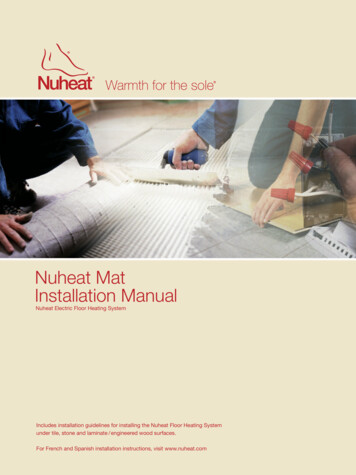
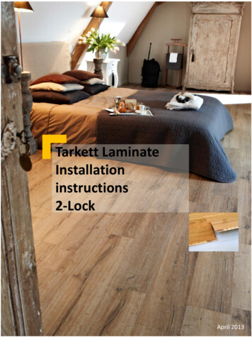
SECTION 2: INSTALLATION2.1INSTALLATION : PLANNING2.11INSTALLATION LAYOUT PLAN CONT.6. Draw the cable runs on the Installation Layout Plan. See Figure 2.16.ThermostatCold LeadHeating CablePerimeterCable Guides*StabilizingCable Guides*Buffer ZoneFIGURE 2.16: Installation Layout Plan Example7. D uring installation, additional “Stabilizing Cable Guides” must be inserted at 3’ ( ft ) to4’ ( ft ) intervals. Determine the location of these additional guides and draw them on theInstallation Layout Plan. See Figure 2.16.*8. P redicting where the cable will end is difficult. As such, it’s important to include a“Buffer Zone” in the Installation Layout Plan; an area where heating is not essential(e.g. behind the toilet, behind a door, or any other low traffic area). This “Buffer Zone”can be used to accommodate any excess cable or remain unheated if cable is neededelsewhere. See Figure 2.16.Identify a “Buffer Zone” on the Installation Layout Plan. Conduct insulation and resistance tests and record the resistance readingson page 7.*Not applicable if installing Nuheat Cable with Nuheat Membrane.Nuheat Cable Installation Guide9
SECTION 2: INSTALLATION2.2INSTALLATION: CABLE & GUIDES2.21INSTALLING THE CABLEIf installing Nuheat Cable in Nuheat Membrane, please refer to installation steps insection 2.8.1. C reate a hole / notch in the wall sill plate below the thermostat electrical connectionbox to allow the cold lead to be routed to the electrical box.2. If necessary, create a small groove on the subfloor to accommodate the mechanicaljoint and / or cold lead (approximately ¼” deep). The groove should be as close to thesill plate hole as possible.3. Secure the mechanical joint to subfloor with duct tape or hot glue.FIGURE 2.23: Secure the cold lead to the subfloor4. Secure excess cold lead to the subfloor using industrial-grade hot glue. Ensure the glue-gun tip does not touch any portion of the cold lead orheating cable.5. N uheat Cable Guides are designed to snap together. See Figure 2.25. Use hotglue, staples, nails or #6 - ½” screws to secure the Nuheat Cable Guides to thesubfloor per the Installation Layout Plan. If using screws / nails / staples, use3 to 4 screws / nails / staples per Nuheat Cable Guide.FIGURE 2.25: Snap together Nuheat Cable Guides10Nuheat Cable Installation Guide
SECTION 2: INSTALLATION2.2INSTALLATION: CABLE & GUIDES2.21INSTALLING THE CABLE CONT.6. Install Nuheat Cable according to the Installation Layout Plan. Individual runs of Nuheat Cable should be spaced 3” apart for 12 watts/sq ft.For 15 watts/sq ft, alternate spacing 3”/2”. Nuheat Cable Guide anvilsare 1” wide.FIGURE 2.26: Install the heating cable7. E nsure individual cable runs maintains moderate tension. This willprevent the cable from floating during the floor covering preparation.FIGURE 2.27: Install the heating cableNuheat Cable Installation Guide11
SECTION 2: INSTALLATION2.2INSTALLATION: CABLE & GUIDES2.21INSTALLING THE CABLE CONT.8. U se duct tape, hot glue or a Nuheat Cable Guide to secure the end seal of the heatingcable to the subfloor.FIGURE 2.28: Secure the end seal9. I nstall “Stabilizing Cable Guides” per the Installation Layout Plan. These additional“Stabilizing Cable Guides” will ensure the heating cables does not float during theself-levelling process. To make installation of the “Stabilizing Cable Guides” easier, flip the cable guideupside down to smoothly pass underneath the cable runs. Then flip the guidesover to secure them to the subfloor and snap the cables into place.FIGURE 2.29: Install stabilizing guides Conduct insulation and resistance tests and record the resistance readingson page 7.12Nuheat Cable Installation Guide
SECTION 2: INSTALLATION2.3INSTALLATION: THERMOSTAT PROBE2.31INSTALLING THE FLOOR-SENSING PROBEThermostat installation instructions are included with each Nuheat floor-sensingthermostat. To ensure full functionality of the floor-sensing thermostat, it is vital toinstall the floor-sensing probe at this point in the installation.1. S ecure the tip of the floor-sensing probe to the subfloor using duct tape.When choosing where to install the probe, ensure: The probe is away from excess temperature swings ( i.e. direct sunlight, drafts, areascovered by rugs or fixed furniture). The probe is installed a minimum of 12” into the heated area. The probe is centered between two runs of heating cable without touching any portionof the heating cable.FIGURE 2.31: Secure the floor-sensing probe2. Route the thermostat probe through the sill plate hole and up to the thermostatelectrical box. As per electrical code, the sensor probe can run up the wall with the coldlead but must enter through the front of the electrical box connect to the thermostat. Perform a visual inspection of the cable. If the cable appears to be damagedor defective, halt installation immediately and contact the Nuheat TechnicalServices Team at 1.800.778.WARM( 9276 ).Nuheat Cable Installation Guide13
SECTION 2: INSTALLATION2.4INSTALLATION: SELF-LEVELER2.41 FLOOR PREPARATION: SELF-LEVELING METHOD(Recommended Method)1.Prepare the subfloor and self-levelling compound as per manufacturer’s instructions.2. Pour the self-leveling compound over the heating cable and guides. Use a scraperor flat trowel to spread the self-leveling compound. The heating cable should becompletely covered with only the top of the guides showing.FIGURE 2.42: Self-leveling compound method3. Allow the self-leveling compound to set as per manufacturer’s instructions. Conduct insulation and resistance tests and record the resistance readingon page 7.4.Proceed with laying the floor covering as per the manufacturer’s instructions. Before activating Nuheat, allow setting material (self-leveling / thinsetmortar compound and grout) to cure according to manufacturer’s instructions(usually 72 hours to one week).14Nuheat Cable Installation Guide
SECTION 2: INSTALLATION2.5INSTALLATION: THINSET MORTAR2.51FLOOR PREPARATION: THINSET MORTAR METHOD1. Prepare the thinset mortar as per manufacturer’s instructions.2. Use a flat trowel at a 45 angle ( following the same direction as the cable ) to spreada thin layer of thinset mortar over the cable and guides. The heating cable should becompletely covered with only the top of the guides showing.FIGURE 2.52: Thinset mortar method3. Allow the thinset mortar to set as per manufacturer’s instructions. Conduct insulation and resistance tests and record the resistance readingon page 7.4. Proceed with laying the floor covering as per manufacturer’s instructions. Before activating Nuheat, allow setting material (self-leveling / thinset mortarcompound and grout) to cure according to manufacturer’s instructions (usually72 hours to one week).Nuheat Cable Installation Guide15
SECTION 2: INSTALLATION2.6INSTALLATION: DIRECT METHOD2.61FLOOR PREPARATION: DIRECT METHODTile/Stone installations only.1. Prepare the thinset mortar as per manufacturer’s instructions.2. U se a minimum 3/8” x 3/8” square-notched trowel to spread a thin layer of thinsetmortar over the Cable ( following the same direction as the cable ).FIGURE 2.62: Direct method Conduct insulation and resistance tests and record the resistance readingon page 7.3. T o ensure each tile has adequate adherence to the subfloor, apply a layer of thinsetmortar to the backside of the tile (back-buttering). Lay the tile directly on the thinsetmortar and firmly press down on the tile. This technique has a high level of difficultyand is not recommended for inexperienced tile installers. Before activating Nuheat, allow setting material (self-leveling / thinsetmortar compound and grout) to cure according to manufacturer’s instructions(usually 72 hours to one week).16Nuheat Cable Installation Guide
SECTION 2: INSTALLATION2.7INSTALLATION: WET ENVIRONMENT2.71FLOOR PREPARATION: WET ENVIRONMENTNuheat Cable may be installed in wet environments such as shower beds or saunas*.Nuheat Cable must be installed on top of the mortar bed/dry pack before the installationof the tile/stone.1. A fter the mortar bed has fully set, use hot glue to secure Nuheat Cable Guides ontothe mortar bed.2. I nstall the Nuheat Cable. Ensure the heating cable maintains a moderate tensionthroughout.3. Conduct insulation and resistance tests and record the resistance reading on page 7.* Installations must be in accordance with the Canadian Electrical Code Part 1 or theNational Electrical Code (US) whichever is applicable.Nuheat Cable Installation Guide17
SECTION 2: INSTALLATION2.7INSTALLATION: WET ENVIRONMENT2.71FLOOR PREPARATION: WET ENVIRONMENT CONT.4. D ue to the slope of the mortar bed, the cable will become suspended above certainareas of the shower floor. Use Nuheat Cable Guides to hold the cable onto the mortarbed, ensuring it follows the contours of the slope. Do not allow the tip of the hot glue gun to touch the cable as it maycause damage.5. Use the Thinset Mortar Method (refer to page 15) to prepare the floor.6. Install flooring as per manufacturer’s instructions.18Nuheat Cable Installation Guide
SECTION 2: INSTALLATION2.8INSTALLATION: NUHEAT MEMBRANE2.81 INSTALLING THE MEMBRANERefer to the Nuheat Membrane Installation Manual for methods to secure the membraneto the subfloor.2.82 INSTALLING THE HEATING CABLE1. C reate a hole/notch in the wall sill plate below the thermostat electrical connection boxto allow the cold lead to be routed to the electrical box.2. I f necessary, create a small groove in the membraneto accommodate the mechanical joint and/or cold lead(approximately ¼” deep). The groove should be as closeto the sill plate hole as possible.3. S nap/Secure the mechanical joint/splice connection of the heating cable into thechannels in the membrane using duct tape or hot glue.4. S nap/Secure the heating cable around the pillars of themembrane. Ensure there is a minimum of two pillars of themembrane between two runs of heating cable (2.5” or 64mm).5. E nsure individual cable runs maintains moderate tension. This will prevent the cablefrom floating during the floor covering preparation. If necessary, use tape, hot glue, orrubber fasteners to secure the heating cable to the membrane.6. U se tape or hot glue to secure the end seal of the heating cable to the membrane.Nuheat Cable Installation Guide19
SECTION 2: INSTALLATION2.8INSTALLATION: NUHEAT MEMBRANE2.83 INSTALLING THE FLOOR SENSOR PROBEThermostat installation instructions are included with each floor-sensing thermostat.To ensure full functionality of the floor-sensing thermostat, it is vital to install thefloor-sensing probe at this point in the installation.1. U sing an ohmmeter (or multimeter), test floor-sensing probe.Set resistance range to 20KΩ. Probe wires should read between 8K - 12K ohms.2. S ecure the tip of the floor-sensing probe to the membrane using duct tape. Whenchoosing where to install the probe, ensure:a. T he probe is away from excess temperature swings(i.e. direct sunlight, drafts, areas covered by rugs orfixed furniture).b. The probe is installed a minimum of 12” into the heated area.c. The probe is centered between two runs of heating cable without touchingany portion of the heating cable.3. Route the thermostat probe through the sill plate hole and up to the thermostatelectrical box. As per electrical code, the sensor probe can run up the wall with the coldlead but must enter through the front of the electrical box connect to the thermostat.Perform a visual inspection of the cable. If the cable appears to be damaged ordefective, halt installation immediately and contact the Nuheat Technical Services Teamat 1.800.778.WARM(9276).2.84 COVERING THE HEATING CABLE AND INSTALLING TILE1. R efer to membrane installation instructions for appropriatethinset mortar to prepare.2. U se a flat trowel at a 45 angle to spread a thin layer of thinset mortar over the cableand membrane. The heating cable should be completely covered with only the top of themembrane’s pillars showing.3. C onduct insulation and resistance tests and record the resistance reading and recordthe resistance reading on page 7.4. R efer to membrane installation instructions for tile installation steps.20Nuheat Cable Installation Guide
SECTION 3: ELECTRICAL CONNECTIONS3.1ELECTRICAL CONNECTIONS3.11ELECTRICAL CONNECTIONSElectrical connections must be made by a certified electrician to validate the warranty.All wiring must follow specifications set out in the Canadian Electrical Code Part 1 orthe National Electrical Code ( US ) whichever is applicable and local electrical inspectionregulations and authorities. Nuheat Cable should be connected to a dedicated electricalcircuit. Nuheat Cable must be connected to the electrical service through a Class “A”Ground Fault Circuit Interrupter ( GFCI ) or a GFCI circuit breaker. The supply leads of theNuheat Cable must be routed inside suitable conduit unless local electrical codes stateotherwise. Check with the local authority having jurisdictionto determine requirements.Refer to the thermostat installation instructions ( included with thermostat ) for completewiring instructions. Thermostats should be installed at an appropriate height and in anaccessible location in the same room that the thermostat is controlling.All thermostats must be UL Listed and/or CSA C/US Approved devices.A floor-sensing probe is included with each Nuheat thermostat.Nuheat thermostats are equipped with Class “A” GFCI protection.1. Pull the lead wires into the electrical connection box via a suitable conduit. The electrical ratings label must be fixed to the cold lead and visible at theterminal junction box. Removing the label will automatically void the warranty.2. S ecure Nuheat Cable to the box connector hub and install a protective nail plate tocover the sill plate hole.3. C onnect the metal braid wire ( ground ) to the electrical box ground screw or groundcopper conductor wire.4. A ttach the corresponding lead wires to the junction box using CSA Certified / UL Listedcable fittings. The ‘line’ wire is identified by yellow / white or red color. The NuheatCable System must be connected using minimum 14AWG supply conductors. Supplyconductors shall be suitable for residential wiring according to local and nationalelectrical codes.Nuheat Cable Installation Guide21
SECTION 4: THERMOSTATS4.1THERMOSTATSSIGNATURE THERMOSTATWi-fi – Enabled Floor Heating Thermostat WiFi-enabled 3.5” Color touchscreen Energy usage monitor 7-day programmability Dual-voltage (120 V & 240 V)HOME THERMOSTATUniversal Floor Heating Thermostat 3.5” Color touchscreen Energy usage monitor 7-day programmability Dual-voltage (120 V & 240 V)ELEMENT THERMOSTATNon-programmable Thermostat Manual temperature control Dual-voltage (120 V & 240 V)22Nuheat Cable Installation Guide
SECTION 4: WARRANTY4.2WARRANTY INFORMATIONWARRANTY INFORMATIONNuheat offers a 25-year Limited Product Warranty and/or 25-year Limited Total Care*Warranty when installed by a Certified PRO Installer.The online warranty registration form must be completed at www.nuheat.com withinthirty (30) days from the date of installation and kept by the homeowner, together witha copy of the commissioning report, relevant invoice, and photographs, showing theproduct(s) in their entirety after installation but before the installation of the flooringmaterial.* Total Care warranty is an upgrade of our standard product warranty and additionally covers repairor replacement of the Product and restoring the floor in its original state or, if not possible, to anequivalent standard, at no cost to the Buyer. In order to remedy the defect, Pentair must haveaccess to 1m² (10 ft²) of the floor covering material.For more information, please call: 1.800.778.WARM(9276)or email: res.customercare@pentair.com.Nuheat Cable Installation Guide23
WWW.NUHEAT.COMNORTH AMERICATel: 1.800.778.9276Fax: 1.604.529.4404res.customercare@pentair.comPentair and Nuheat are owned by Pentair or its global affiliates. All other trademarksare the property of their respective owners. Pentair reserves the right to changespecifications without prior notice. 2017 Pentair.THERMAL BUILDING tion-EN17/03
CâbleSYSTÈMES DE CHAUFFAGE ÉLECTRIQUEPAR RAYONNEMENT À PARTIR DUPLANCHERGUIDE D’INSTALLATIONSOLUTIONS DE CONSTRUCTION THERMIQUEGuide d’installationWWW.NUHEAT.COM– Câble Nuheat1
TABLE DES MATIÈRESSECTION 1 : PRÉPARATION À L’INSTALLATION1.1 Directives d’installation .1.2 Avant de commencer .1.3 Essais d’isolation et de résistance .1.4 Tableau d’isolation et de résistance .4567SECTION 2: INSTALLATION2.1 Planification de l’installation . 82.2 Câbles et garde-câbles . 102.3 Sonde du thermostat. 132.4 P réparation du plancher : Méthode du mélange autolissant(méthode recommandée). 142.5 Préparation du plancher : Méthode du mortier à pose simplifiée. 152.6 Préparation du plancher : Méthode directe. 162.7 Préparation du plancher : Milieu humide. 172.8 Préparation du plancher : Nuheat Membrane.19SECTION 3 : CONNEXIONS ÉLECTRIQUES3.1 Connexions électriques . 21SECTION 4 : THERMOSTATS ET INFORMATION SUR LA GARANTIE4.1 Thermostats . 224.2 Information sur la garantie . 23Guide d’installation – Câble Nuheat3
SECTION 1: PRÉPARATION DE L’INSTALLATION1.1DIRECTIVES D’INSTALLATION L ’installation de ce produit de chauffage doit être effectuée conformément auxdirectives du fabricant et au Code canadien de l’électricité (partie 1) ou auNational Electrical Code des États-Unis, s’il y a lieu, avec la permission desautorités compétentes. Cet équipement doit être installé uniquement par du personnel qualifié connaissantbien la construction et l’utilisation de l’équipement et les risques possibles. Il faut user de précautions afin de prévenir tout risque de décharge électrique,d’incendie et de blessure durant l’installation de cet équipement. Le câble Nuheat doit être branché à un circuit électrique distinct. Il est obligatoire d’installer un disjoncteur de fuite de terre (GFCI) de classe A pourchaque installation Nuheat. Tous les thermostats Nuheat sont munis d’un disjoncteurGFCI de classe A. Mettre les circuits hors tension avant l’installation ou l’entretien. NE PAS UTILISER d’outils électriques/pointus pour nettoyer les lignes de ciment. Les guides de câbles Nuheat et la Nuheat Membrane sont les seuls accessoiresapprouvés pour fixer le câble Nuheat au faux plancher Indiquer sur le panneau électrique le circuit utilisé pour le système de câbles Nuheat. Le faux plancher doit être préparé conformément aux spécifications ANSI. Les câbles Nuheat ne doivent pas se chevaucher ni se croiser; aussi, ils ne doiventjamais être coupés, raccourcis ou modifiés. Toute la partie chauffante du câble Nuheat et du joint mécanique doit être fixée auplancher et recouverte de mélange autolissant ou de mortier à pose simplifiée. N’installez pas Nuheat Cable en contact direct avec des surfaces combustibles etn’installez pas dans / sur / sous les murs ou dans les placards. Dans le cas de faux plancher en b
Nuheat Cable Installation Guide 5 SECTION 1: INSTALLATION PREPARATION 1.2 BEFORE YOU START 1.21 HEATING CABLE COMPONENTS Nuheat Cable is comprised of: Heating Cable (red) The longest portion of Nuheat Cable, this segment of Nuheat Cable is strung onto the subfloor and generates the heat underneath your surface covering. Cold Lead (black)