Transcription
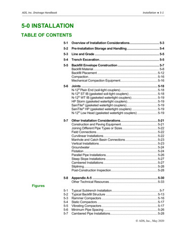
ADS, Inc. Drainage HandbookInstallation 5-15-0 INSTALLATIONTABLE OF CONTENTS5-1Overview of Installation Considerations. 5-35-2Pre-Installation Storage and Handling . 5-45-3Line and Grade . 5-55-4Trench Excavation. 5-55-5Backfill Envelope Construction . 5-7Backfill Material. 5-8Backfill Placement . 5-12Compaction. 5-16Mechanical Compaction Equipment. 5-165-6Joints . 5-18N-12 Plain End (soil-tight couplers) . 5-18N-12 ST IB (gasketed soil-tight couplers) . 5-18N-12 WT IB (gasketed watertight couplers). 5-19HP Storm (gasketed watertight couplers). 5-19SaniTite (gasketed watertight couplers). 5-19SaniTite HP (gasketed watertight couplers) . 5-19N-12 Low Head (gasketed watertight couplers) . 5-195-7Other Installation Considerations. 5-21Construction and Paving Equipment . 5-21Joining Different Pipe Types or Sizes. 5-22Field Connections . 5-22Curvilinear Installations. 5-22Manhole and Catch Basin Connections . 5-23Vertical Installations . 5-23Groundwater . 5-24Flotation . 5-24Parallel Pipe Installations. 5-26Steep Slope Installations . 5-27Cambered Installations . 5-27Sliplining. 5-28Post-Construction Inspection. 5-285-8Appendix A-5 . 5-30Other Technical Resources . 5-335-15-25-35-45-55-65-7Typical Subtrench Installation . 5-7Typical Backfill Structure . 5-13Rammer Compactors . 5-16Static Compactors . 5-17Vibrating Compactors . 5-17Minimum Pipe Spacing . 5-26Cambered Pipe Installations. 5-28Figures ADS, Inc., May 2020
ADS, Inc. Drainage HandbookInstallation 5-2Tables5-15-25-3Minimum Trench Widths . 5-5Classes of Embedment and Backfill Materials . 5-10General Recommendations for Installation andUse of Soils & Aggregates . 5-155-4 Compaction Equipment Selection Guide. 5-185-5 Guidelines for Joint Performance Selection. 5-205-6 Temporary Cover Requirements for Light Construction Traffic . 5-215-7 Bending Radii for ADS Thermoplastic Pipe . 5-235-8 Approximate Weight of ADS Thermoplastic Pipes . 5-255-9 Minimum Cover Required to Prevent Flotation. 5-26A-5-1A Available Product-Specific Technical Literature &Detail Drawings . 5-30A-5-1B Available (U.S.) Product-Specific Technical Literature & DetailDrawings .5-30A-5-2A Minimum Installation Requirements for ADSThermoplastic Products (U.S.). 5-31A-5-2B Minimum Installation Requirements for ADSThermoplastic Products (Canadian) .5-32BUYER/USER IS RESPONSIBLE FOR SERVICEABILITY OF THE PRODUCT IN ANY GIVENAPPLICATION. SELLER IS NOT RESPONSIBLE FOR INJURY OR DAMAGE RESULTING FROMIMPROPER INSTALLATION, NONCOMPLIANCE WITH THESE GUIDELINES FOR INSTALLATION OFPRODUCT, OR USE OUTSIDE THE GUIDELINES SET FORTH HEREIN. ADS, Inc., May 2020
ADS, Inc. Drainage HandbookInstallation 5-35-1 OVERVIEW OF INSTALLATIONCONSIDERATIONSInstallation of ADS pipe is in most respects very much like that of anyquality pipe installation. The strength of a pipe system shall beconsidered a combination of the pipe itself and the backfill envelope.Proper construction maximizes the drainage capabilities designed into thepipe by maintaining alignment and load-carrying ability.Recommendations for proper backfill and installation for ADS productsare based primarily on the requirements of ASTM D2321 "RecommendedPractice for Underground Installation of Flexible Thermoplastic SewerPipe", CSA B182.11-11 “Standard Practice for the Installation ofThermoplastic Drain, and BNQ 1809-3 “Construction Work-GeneralTechnical Specification- Drinking Water and Sewer Lines”. Thesehandbooks are not intended to replace standard industry or projectspecifications, but to provide guidance based on our experience, researchand recommendations for proper product performance.The elements regarding backfill that are addressed in this section are asfollows:Proper backfill material selection - A variety of materials can be usedas structural backfill with the final decision, many times, based on what ismost available locally. Native soil may be an appropriate materialproviding it meets the basic criteria established in this section.Proper backfill compaction - Compaction forces out air and moisture toprovide a more stable structure. Minimum compaction levels are basedon the material characteristics and the design load; some situations mayrequire the use of mechanical compactor while others require simplytamping the material to eliminate voids.Proper backfill structure - An adequate quantity of structural backfill isnecessary to ensure adequate support. Undisturbed native soil from atrench wall often provides additional support. Typical trench dimensionsand the effect of the trench wall are discussed in this section.In addition, this section discusses job-site handling, trench constructionand pipe installation for ADS products, compaction methods, and severalspecialized installation considerations.Federal regulations covering safety for construction arepublished in the Safety and Health Regulations for Constructionunder the Department of Labor, Occupational Safety and HealthAdministration (OSHA). These regulations define practices,which must be followed. ADS, Inc., May 2020
ADS, Inc. Drainage HandbookInstallation 5-45-2 PRE-INSTALLATION STORAGE ANDHANDLINGThermoplastic pipes such as polyethylene and polypropylene arelightweight and easy to use. While no special care is needed in handlingand installation a few precautions should be set forth. Follow all applicable safety regulations when handling pipe. The pipe shall not be dropped from the delivery truck into an opentrench, or onto uneven surfaces. Avoid dragging or striking the pipe against another pipe or object. Avoid dragging the pipe across the ground. Avoid any impact to the bell or spigot. Do not drive over the pipe prior to installation. Inspect the pipe and joining systems before installation. Care shall be taken to not over home the pipe during assembly.Many ADS drainage products are available palletized allowing forconvenient transporting and orderly storage. If the products were notreceived on a pallet, the pipe should be carefully stacked. One methodcommonly used is to secure the bottom lengths of pipe together side-byside, or use stop blocks, and then place additional pipe on top. Wherepipe is stock piled, the total pile height shall not exceed 5-feet and thepipe must be adequately restrained to prevent pile collapse. Do not walkon stock piled pipe. Additional handling and storage information isavailable upon request.Ambient temperature extremes do not affect the strength or handlingcharacteristics of ADS pipe products. Cold temperatures can affect theimpact resistance of some thermoplastics, although polyethylene andpolypropylene remain highly impact resistant. In-house quality checks onpolyethylene products demonstrate that the impact resistance at zerodegrees F (-18C) is many times that required by specification.Additionally, hot weather, especially when coupled with direct sunlight, willraise the pipe temperature, but will not significantly affect handling orinstallation behavior.Depending on the product, either carbon black or another UV stabilizer isadded to the polyethylene or polypropylene to protect against ultravioletlight; unprotected plastic can become less impact resistant over time.Such additives are required by the specification and protect the pipeduring storage periods at the manufacturing facility and at the job site.Ultraviolet light is no longer an issue after installation.Long-term exposure to ultraviolet light causes slightly different results.The UV stabilizer protects the pipe for several years, after which theimpact strength of the exposed layer, generally 0.001-inch (0.03mm), issignificantly reduced. This damaged layer then functions in shielding theremainder of the pipe wall from any further damage. There are HDPE ADS, Inc., May 2020
ADS, Inc. Drainage HandbookInstallation 5-5culverts, currently under observation, that were installed in 1974. Theculverts have retained nearly all of their original strength characteristicsand support strong evidence of continued service.5-3 LINE AND GRADEStorm drain and sewer pipe systems are designed to providehydraulic capacity based on pipe size and slope. The alignment orline of the pipe is the horizontal location of the pipe while the grade isthe vertical slope of the pipe. In order for a pipe system to function asdesigned, it is important to install the pipe to the proper line andgrade.Generally, no special practices are required to maintain line andgrade; however, certain installation techniques can greatly increasethe system performance and rate of installation.Alignment is established by a field survey. Once the trench isexcavated on line, the pipe bedding shall be placed to properthickness. The top of the bedding shall be adjusted to allow for thedifference between the plan invert (flowline) and pipe profile wallthickness. To determine the dimension to be subtracted from the pipeinverts indicated on the plans when checking bedding elevationsmeasure the distance from the interior side of the liner to the crown ofthe corrugation.5-4 TRENCH EXCAVATIONThe width of the trench depends on the pipe diameter, backfillmaterial, and the method of compaction. Trenches that are toonarrow will not allow for proper pipe installation, whereas trenchesthat are overly wide are unnecessarily costly. As a practical matter,standard bucket sizes may also factor into the decision. The designengineer may modify the trench widths based on an evaluation of thecompetency of the in-situ materials, the quality and compaction levelof the backfill, the design loads and the compaction equipment to beused. In lieu of the engineer's recommendations or governing agencyspecifications, the following trench widths are suggested in table 5-1.Table 5-1Minimum Trench WidthsNominal PipeDiameter,in. (mm)Minimum Trench in.(m)Nominal PipeDiameter,in. (mm)Minimum Trench in.(m)4 (100)21 (0.5)24 (600)48 (1.2)6 (150)23 (0.6)30 (750)56 (1.4)8 (200)26 (0.7)36 (900)64 (1.6)10 (250)28 (0.7)42 (1050)72 (1.8)12 (300)30 (0.8)48 (1200)80 (2.0) ADS, Inc., May 2020
ADS, Inc. Drainage HandbookInstallation 5-615 (375)34 (0.9)54 (1350)88 (2.2)18 (450)39 (1.0)60 (1500)96 (2.4)Trench widths should only be wide enough to permit the adequateplacement and compaction of the embedment materials. This idealtrench width is normally referred to as the minimum trench width. It isdesignated in accordance with national standards and generally assuresthe width allows for backfill material to flow on either side of the pipe andpermits the compaction of this material. If the width is not sufficiently widefor the materials and proposed compaction methods a wider trenchallowing for proper installation shall be constructed.In very poor native soils (for example; peat, muck, or highly expansivesoils), a wider trench width with possibly filter fabric may be required. Thiswider trench width shall be based on an evaluation of the in-situ soil, andthe design and construction loads.Trench widths for pipe are often determined by the bucket size availablefor the excavator. In many cases, the bucket width can significantlyexceed the ideal trench width. Wide trenches are not only costly toexcavate and fill with backfill material they actually reduce the structuralintegrity of the pipe/backfill system. This fact is noted in the AASHTOLRFD Bridge Construction Specification, Section 30, “Trenches shall bekept to the specified width as any increase in trench width will increasethe load on the pipe.”Years of consolidation create a very stable soil environment. The desireis to destroy as little of that stability as necessary when digging thetrench. Stable trench walls actually enhance the structural integrity of thesystem when the trench is relatively narrow. Overly wide trenches alsorequire more backfill material and more compaction which are typicallynot as stable as the undisturbed native material. A stable trench wall ischaracterized as one that can stand without support; however this doesnot refer to the possible need of trench wall supports to comply withOSHA.It should be noted that although the pipe will have less load in a narrowtrench condition, a wide trench application is used for the designmethodology for thermoplastic pipe found in AASHTO LRFD BridgeDesign Specifications Section 12. This point is clearly illustrated inSection 12.12, “narrow trenches yield a desirable level of conservatism,since the transfer of the load to in-situ trench wall is not considered inflexible pipe design.”The depth of the trench is dictated by the geography of the site and thepipe slope required. However, if an adequate foundation for the pipe isnot available at the desired depth, additional excavation will be needed.Rock outcroppings, muck, and other unsuitable materials do not provideproper support. They shall be removed and replaced with suitablegranular material. Refer also to Figure 5-1.Trenching shall be completed in existing soils with sidewalls reasonablyvertical to the top of the pipe. For positive projection embankment ADS, Inc., May 2020
ADS, Inc. Drainage HandbookInstallation 5-7installations, the embankment material shall be placed and compacted toa minimum of one (1') foot above the pipe and the trench excavated intothe embankment. When excavation depths or soil conditions requireshoring or use of a trench box, the bottom of the shoring or trench boxshould be placed no lower than the top of the pipe. This preventsdisruption of the backfill envelope when removing the shoring or trenchbox. Dragging the trench box shall only be done if it does not damage thepipe or disrupt the backfill, otherwise, the box shall be lifted vertically intoits new position. If this practice cannot be followed, consideration shouldbe given to leaving the shoring in place. When the trench box must belocated below the top of the pipe, the most effective way to maintain asound system is to provide a ‘sub trench’ within which to place the pipeand backfill. For safety, the bottom of the trench box should not be greaterthan 24” above the bottom of the trench. For more information on the useof trench boxes, refer to Technical Note 5.01: Recommended Use forTrench Boxes.Figure 5-1Typical Sub Trench Installation5-5 BACKFILL ENVELOPE CONSTRUCTIONBackfill construction shall be evaluated as part of the structural design ofpolyethylene and polypropylene pipe like it is for other pipe materials.ASTM D2321/ CSA B182.11-11 serve as the basis for installationrecommendations in trafficked installations. Acceptable backfill materialsand construction methods are very similar or, in many cases, identical tothose required for other types of pipe material.The primary purpose of the backfill envelope is to provide long-termsupport to the pipe. In a properly constructed backfill envelope, the loadsare distributed across the crown of the pipe to the material along the sidesand then to the pipe bedding and foundation. This load arching effectreduces the total load applied to the pipe.The load that a flexible pipe will carry is related to the backfill envelopeconstruction. The load-carrying capacity of a pipe/backfill system will be ADS, Inc., May 2020
ADS, Inc. Drainage HandbookInstallation 5-8determined by a combination of the backfill material, the level ofcompaction, and the placement of the backfill material. However, the typeof application may also influence what type of backfill is required. Theseand other related issues are discussed in subsequent paragraphs in thissection.BACKFILL MATERIALMaterial selection is the first and most important step to creating astructurally sound backfill envelope. In general, backfill material should beof an aggregate nature, able to be compacted, if necessary, into astructurally sound structure. A variety of materials, including some nativesoils, meet these requirements.Backfill offers passive resistance, termed the “modulus of soil reaction”.The modulus of soil reaction is determined by a combination of thematerial and the amount of compaction. The type of material (sand,gravel, clay, etc.) and compaction level (standard Proctor density)determine overall strength of the backfill. Some research indicates thatother factors, such as the beneficial effects of trench walls, may add to theconservancy of the backfill strength, although those relationships areoften neglected. (This information assumes the trench walls are at leastas strong as the backfill material.)The strength of the backfill can be described using different parameters.One way is by describing it in terms of the modulus of soil reaction (E’),which is an empirical value developed by the Bureau of Reclamation tocalculate deflection. Another parameter used to describe backfill strengthis the secant constrained soil modulus (MS). Values for MS and E’ arediscussed further in the Structures chapter of this handbook.Recommendations for soil type and compaction level will vary based onthe application and product; Appendix A-5 provides product-specificguidelines and literature references. Shallow, non-trafficked installationsmay not require the same level of backfill quality, but any modificationsshould be discussed with ADS engineers prior to establishing backfillcriteria on a particular project. Installations involving higher loadssometimes require a higher soil strength; ADS engineers can also provideadditional guidance on backfill requirements in these situations.As discussed in the Structures section of this handbook, it is thecombination of the type of material and compaction level that willdetermine the soil strength. When a variety of options will work in aparticular installation, the final decision can depend on what is mostavailable locally in order to keep the cost of the installation to a minimum.Native soil may be specified depending on the ADS product beinginstalled, the application and when following the requirements of Table 52 and the respective technical literature as listed in Appendix A-5. Usingnative soil eliminates the cost of imported backfill material and the effortspent grading or hauling the excavated material off site. If the nativematerial is not acceptable, then appropriate material will need to bebrought in. ADS, Inc., May 2020
ADS, Inc. Drainage HandbookInstallation 5-9Flowable fill, also known as controlled low strength material (CLSM),controlled density fill (CDF) and slurry fill, is another, more specialized,type of backfill material that is increasing in use throughout the country.This material is a mixture of soil, cementitious material, and water. Withacceptable in-situ material, flowable fill trench widths can be reduced.Although the structural integrity of flowable fill is excellent, it will misalignor float the pipe unless precautions, such as weighting the pipe or pouringthe flowable fill in lifts, are taken. For more information on the use offlowable fill refer to Technical Note 5.02: Flowable Fill Backfill for Pipe. ADS, Inc., May 2020
ADS, Inc. Drainage HandbookInstallation 5-10Table 5-2Classes of Embedment and Backfill MaterialsASTM D2321(A)(CSA B182.11)ClassDescriptionASTM edrock,angularCN/AAngular crushed stoneor rock, crushedgravel, crushed slag;large voids with little orno fines5, 56,57(D), 6,67(D)GWWell-graded gravel,gravel-sand mixtures;little or no fines5, 6GPPoorly-graded gravels,gravel-sand mixtures;little or no fines56, 57,67SWWell-graded sands,gravelly sands; little orno finesClean,coarsegrained soilsSPFCoarsegrained soilswith finesIIIE)N/AGMSilty gravels, gravelsand-silt mixturesGravel &sandwith 10%finesGCClayey gravels, gravelsand-clay mixturesOrganicsoils orHighlyorganic soils1 ½ in.3/8”No. 4(40mm)(9.5mm)(4.75mm)No.200(0.075mm)100% 25% 15% 12%Silty sands, sand-siltmixturesSCClayey sands, sandclay mixturesMLInorganic silts andvery fine sands, rockflour, silty or clayeyfine sands, silts withslight plasticityCLInorganic clays of lowto medium plasticity;gravelly, sandy, or siltyclays; lean claysMLInorganic silts andvery fine sands, rockflour, silty or clayeyfine sands, silts withslight plasticityN/ACLInorganic clays of lowto medium plasticity;gravelly, sandy, or siltyclays; lean claysN/AMHInorganic silts,micaceous ordiatomaceous finesandy or silty soils,elastic siltsN/ACHInorganic clays of highplasticity, fat claysN/AOLOrganic silts andorganic silty clays oflow plasticityN/AOHOrganic clays ofmedium to highplasticity, organic siltsN/APeat and other highorganic soilsN/APTCG14 ,MG20Atterberg LimitsCoefficientsLLCuPINon Plastic 5%Varies5% to12% 41 to 3 4 1 or 3 61 to 3 6 1 or 3Non PlasticNon Plastic12% to50%N/A 7 & ”A” Line 30%(Retained)100%N/A 4 or ”A” Line 50 30%(Retained)100% 7 & ”A” Line 4 or ”A” Line 50% of“CoarseFraction”100%A-2-7 or A4 or A-6soils with30% orlessretainedon #200sieveSame as forGW, GP, SWand SP 4 or ”A” Line 50% of“CoarseFraction”100%CcN/A 50% of“CoarseFraction”100%A-2-4, A-25, A-2-6,or A-4 orA-6 soilswith morethan 30%retainedon #200sieveSMV(G)Percentage Passing Sieve Sizes 50% of“CoarseFraction”Poorly-graded sands,gravelly sands; little orno finesSands and gravelswhich are borderlinebetween clean andwith edsoilsBNQ2560N/AA1, 5Notation100%IICoarseGrainedSoils,borderlineclean tow/finesASTM D2321 (A) (CSA B182.11) 30%(Retained) 7 & ”A” Line 4 or ”A” Line 50N/A 7 & ”A” Line ”A” Line100%100% 50% 50N/A ”A” LineA5, A7100%100% 50 4 or ”A” Line 50 ”A” Line 50%N/A ADS, Inc., May 2020
ADS, Inc. Drainage HandbookInstallation 5-11Notes:A)B)C)D)E)F)G)Refer to ASTM D2321 / CSA B182.11/ BNQ 2560 for more complete soil descriptions.Class I materials allow for a broader range of fines than previous versions of D2321 / B182.11. When specifying class Imaterial for infiltration systems, the engineering shall include a requirement for an acceptable level of fines.All particle faces shall be fractured.Assumes less than 25% passes the 3/8” sieve.Class IV materials require a geotechnical evaluation prior to use and should only be used as backfill under the guidance of aqualified engineer.Uniform fine sands (SP) with more than 50% passing a 100 sieve behave like silts and should be treated as Class III soils ifallowed.Class V materials shall not be permitted as bedding and backfill material. ADS, Inc., May 2020
ADS, Inc. Drainage HandbookInstallation 5-12Backfill PlacementStorm and sanitary sewers, as well as drainage lines are sometimesplaced on foundations that settle and shift in a non-uniform manner.Fortunately, flexible pipe can accommodate many of these changeswithout detrimental effects. The best construction practices, however,involve placing the pipe on a firm foundation for maximum performanceand structural integrity throughout the design life.In some cases it may be necessary to perform subsurface evaluations ofthe soil conditions where muck, rock, or other unsuitable conditions aresuspected. Zones of soft material, such as muck, allow the pipe to settle,potentially affecting the structural integrity and hydraulic characteristics ofthe system. Rock and rock protrusions apply point loads where theycontact the pipe that can affect the hydraulics or structural integrity of thesystem. It is recommended that unsuitable foundation material beexcavated before installation of the pipe proceeds. Where a rock orunyielding or soft foundation is present, the design engineer or ageotechnical engineer shall be consulted to determine the extent to whichthe undesirable material is to be excavated.BeddingIf no undesirable foundation material is found, a minimum of 4- to 6inches (0.1 - 0.15m) of bedding shall be placed and compacted on thefoundation to equalize load distributions along the invert of the pipe.Refer to Figure 5-2 for a pictorial description of backfill terminology.A stable and uniform bedding shall be provided for the pipe and anyprotruding features of its joints and/or fittings. The middle of thebedding, under the pipe invert, equal to 1/3 of the pipe O.D. should beloosely placed, with the remainder compacted to minimum standardproctor density as listed in Appendix A, Table A-5-2. The same classof material recommended for the initial backfill is suitable for thebedding; however, the compaction requirements for the bedding maybe higher than compaction requirements for the initial backfill toensure the stability of line and grade. Refer to Appendix A-5, Table A5-2 for product-specific installation recommendations for each zone.Note: Where using open-graded material (class I with little fines forexample) in any fill zone, additional precaution must be taken toreduce or eliminate the risk of migration of fines from adjacentmaterial. Precautionary steps could include the use of geotextilebetween the varying fill materials, gradation selection to prevent themigration of fines, or other precautionary measures. Refer to ASTMD2321 / CSA B182.11 for more complete information. ADS, Inc., May 2020
ADS, Inc. Drainage HandbookInstallation 5-13Figure 5-2Typical Backfill StructureHaunch BackfillThe next layer of backfill, the haunching, is the most important since it isthis layer that provides the pipe with support against the soil and trafficloadings. Haunching shall be placed in lifts of 4- to 6-inches (0.10 0.15m) and compacted in accordance with product specific guidelineslisted in Appendix A-5, Table A-5-2 to achieve required depth of fill.Construction of each lift should be repeated up to the spring line.Initial BackfillInitial backfill extends from the spring line to the crown of the pipe. Thisarea of the backfill anchors the pipe and ensures that loads are distributedas evenly as possible into the haunching. The same material used in thehaunching shall be used for the initial backfill. Where differing materialsare used, backfill material size should be selected as to prevent migrationof fines or a geosynthetic shall be used to separate the backfill zones.Additionally, it is crucial to obtain similar backfill strength between fillzones if differing materials are used. Using the same material throughoutthe embedment zone is recommended for all ADS products; however,using different materials between the haunch and initial backfill zonesmay be accomplished under strict guidelines that are outlined in theappropriate product’s fill height table technical note. See Table A-5-1 fora list of fill height table technical notes. ADS, Inc., May 2020
ADS, Inc. Drainage HandbookInstallation 5-14When using a material that requires compaction it is important not to usemechanical compaction equipment directly on the pipe itself. Initialbackfill shall be placed in lifts of 4- to 6-inches (0.10 - 0.15m) andcompacted in accordance with product-specific guidelines in Appendix A5, Table A-5-2 to achieve required depth of fill. Tamp to achieve thespecified compaction, or shovel into the area, eliminating voids, if thematerial doesn’t require mechanical compaction. Construction of each liftshould be repeated until the initial backfill zone is completed.Flowable fill can be used throughout the pipe zone as an alternative tocompacted granular material, however special precautions are necessaryfor a successful installat
Storm drain and sewer pipe systems are designed to provide hydraulic capacity based on pipe size and slope. The alignment or line of the pipe is the horizontal location of the pipe while the grade is the vertical slope of the pipe. In order for a pipe system to function as designed, it is important to install the pipe to the proper line and grade.
