Transcription
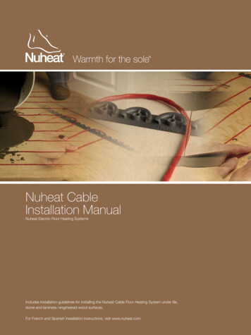
Nuheat CableInstallation ManualNuheat Electric Floor Heating SystemsIncludes installation guidelines for installing the Nuheat Cable Floor Heating System under tile,stone and laminate / engineered wood surfaces.For French and Spanish installation instructions, visit www.nuheat.com
Installation GuidelinesNuheat Industries Limited 2009 Nuheat Industries Limited. All rights reserved.The entire contents of this manual, including but not limited to text, images, and the selection and arrangement of information(collectively the “Materials”), are protected by copyright and other intellectual property laws under the laws of Canada andother countries. THE INSTALLATION OF THIS HEATING PRODUCT SHALL BE IN ACCORDANCE WITH THEMANUFACTURER’S INSTRUCTIONS AND IN ACCORDANCE WITH THE CANADIAN ELECTRICAL CODEPART 1 OR THE NATIONAL ELECTRICAL CODE (US) WHICHEVER IS APPLICABLE. THIS EQUIPMENT SHALL BE INSTALLED ONLY BY QUALIFIED PERSONNEL WHO ARE FAMILIAR WITHTHE CONSTRUCTION AND OPERATION OF THE APPARATUS AND RISKS INVOLVED. CAUTION SHOULD BE TAKEN TO GUARD AGAINST RISK OF ELECTRIC SHOCK, FIRE AND BODILYINJURY DURING THE INSTALLATION OF THIS EQUIPMENT. Nuheat Cable should be connected to a dedicated electrical circuit. It is mandatory to install a Class “A” GFCI or GFCI circuit breaker with each Nuheat installation.NOTE: All Nuheat thermostats come equipped with a built-in Class “A” GFCI. DO NOT USE sharp tools or power tools to clean grout lines. Cleaning grout lines with sharp tools orpower tools may damage the Nuheat Cable System and WILL VOID THE NUHEAT WARRANTY. Nuheat’s Cable Guides are the only devices that are approved to be used to secure Nuheat Cable onto thesubfloor. The use of any other method to secure Nuheat Cable onto the subfloor (e.g. staples or nails) WILLVOID THE NUHEAT WARRANTY. Indicate on the electrical panel which circuit is used for the electric floor heating system. Subfloor must be prepared in accordance to ANSI specifications. Nuheat Cable cannot be overlapped, crossed, cut, shortened or modified. The spacing between the cable runs (3”) should remain unchanged throughout the installation. The entire heating portion of Nuheat Cable and the mechanical joint must be secured to the floor andcovered with self-leveling compound or thinset mortar. Nuheat Cable should never be installed in / on / underwalls under any circumstance. The Nuheat Cable System should never be installed over an expansion joint. The ambient air temperature must be above 0 C or 32 F when the Nuheat Cable Floor Heating System isinstalled.Heating Cable Series Type 1B and 2D Canada, Type C USAThis cable is an electrical appliance and should be installed in accordance with the Canadian Electrical CodePart 1 or the National Electrical Code (US) whichever is applicable. Its installation should be entrusted to trainedand experienced installers and electricians.
ContentsQuick Reference4Selecting a Kit5Calculating square footage and selecting a kitCompatibleSubfloors6OverviewRequiredMaterials and Tools7Materials and componentsInsulation andResistance Tests8Testing the Nuheat Cable SystemNuheat CableInstallation9Plan installation layoutInstall Nuheat CableInstall the floor-sensor probePrepare floor and install floor coveringCombining Nuheat Cable and Nuheat MatWet environment installationsConnecting the electrical and thermostatControls andAccessories19HarmonySOLOTempoMatSense Pro
Quick ReferenceNuheat Cable Installation at a GlancePlan layoutInstall Nuheat Cable Guides andNuheat CableApply self-leveling compoundand allow time to setInstall flooringMake final connectionsIf you are unfamiliar with the installation of Nuheat Cable, please read thedetailed installation instructions on pages 9 - 18 of this installation manual.4
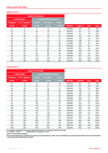
Selecting a KitCalculating Square Footage and Selecting a KitCalculating Square FootageUse the following tips to calculate the square footage of the heated area and to select theproper Nuheat Cable Kit: The heated area of the room should exclude areas beneath counters, fixed furniture orany other areas under which Nuheat Cable System cannot be installed.Tips to calculate square footage: Square footage is calculated by multiplying the length (in feet) by the width (in feet) ofan area. Triangles are squares / rectangles split diagonally in half. To calculate the squarefootage of a triangle, multiply the length (in feet) by the width (in feet) of the triangleand divide by two. If needed, break up the heated area into smaller squares, rectangles and / or trianglesto help calculate the square footage of the entire area. Calculate the square footage ofeach individual area and add the square footages together.CBArea A 3’ x 4’Area B 4’ x 5’Area C 2’ x 2’ 2A 12 sq ft 20 sq ft 2 sq ftTotal 34 sq ftSelectinga Kit Select the kit based on the square footage of the heated area and the correct voltage of theelectrical connection (120V or 240V). A complete product listing table for Nuheat Cable is visit www.nuheat.com forlocated on theback cover of this installationmanual.Alternatively, Cable kit. assistance with selecting the proper Nuheat 5
Compatible SubfloorsOverviewSubfloorsAll subfloors must be prepared in accordance to ANSI specifications.1) Plywood and Cement Board2) Smooth Concrete Slab - Nuheat recommends that the concrete slab be insulated to avoidheat and energy loss3) Scratch Coat - Apply a smooth layer of thinset mortar on top of the scratch coat beforeinstalling Nuheat Cable4) Anti-fracture Membrane - Refer to manufacturer’s installation instructions5) Acoustic Membrane - Refer to manufacturer’s installation instructions6) Ceramic - Refer to self-leveling compound or thinset mortar manufacturer’s instructions7) Mortar Bed / Dry Pack (for shower bed applications)6
Required Materials and ToolsMaterials and ComponentsRequired Materials and ToolsThe following tools / materials are required for a successful Nuheat Cable installation: Ohmmeter (or multimeter) Tools to create a groove in the subfloor Protective nail plate Duct tapeMaterials to secure Nuheat Cable Guides and mechanical joint* to the subfloor: Screws (1/2” long)* Industrial-grade hot glue* Nails Staples* The mechanical joint should be secured to the subfloor using screws (1/ 2” long) orindustrial-grade hot glue only.DO NOT connect Nuheat Cable to power while the cable is still on the spoolNOTE: If your installation layout plan requires excess cold lead to run on the subfloor,secure the excess cold lead to the subfloor using industrial-grade hot glue.Nuheat CableNuheat Cable is comprised of:Heating cable (red) – the longest portion of Nuheat Cable. This segment of Nuheat Cableis strung onto the subfloor and generates the heat underneath your surface covering.Cold lead (black) – the non-heating segment of Nuheat Cable that will run inside the wallcavity to connect to the thermostat. The cold lead is 11’ long.Mechanical joint (red) – the connection joint between the heating cable and the coldlead. The mechanical joint is thicker than the cold lead and has two “ears” that are usedto secure the mechanical joint to the subfloor.7
Conducting Insulation and Resistance TestsTesting Nuheat CableNuheat Cable has been factory tested. The seal on the cable spool warrants the integrity ofthe cable.Insulation TestTo ensure cable is fully insulated: Acquire a digital ohmmeter (or multimeter) with alligator clips or equivalent testingdevice. Set the ohmmeter to the appropriate setting. Place one probe clip on the green wire (ground) and the other probe clip on the yellowwire (red wire for 240V). Confirm that the reading is OL or infinity (open circuit). Repeat these steps to check the reading between the green wire (ground) and the black wire.Resistance TestTo ensure continuity in cable: Acquire a digital ohmmeter (or multimeter) with alligator clips or equivalent testingdevice. Set the ohmmeter to the appropriate setting. Place one probe clip on the black wire and the other probe clip on the yellow wire (redwire for 240V). Confirm that your ohm reading is within 10% / - 5% of the factory reading listed on thecable tag. If installing a Nuheat floor - sensing thermostat, test the sensor probe as well. Put theresistance range to 20K . Probe wires should read between 8K –12K ohms.If the reading on the insulation or resistance test does not pass the requirements at any pointof the installation, halt installation immediately and contact Nuheat Technical Services at1-800-778-WARM (9276).NOTE: Nuheat Cable must be tested before, during and after the installation tovalidate the warranty.8
Nuheat Cable InstallationPlan Installation LayoutStep 1It is VERY IMPORTANT to plan the installation before securing any part of the floor heatingsystem to the subfloor.Follow these steps to assist in planning the installation:1. Start by drawing the dimensions of the room on a piece of paper(grid paper recommended).2. Draw the dimensions of any counters, fixed furniture or any other areas under whichcable cannot be installed.3. Mark the locations of any toilet drains, heating vents or any other heating appliance.Indicate on the drawing that Nuheat Cable should be installed at a minimum distance of:a. 6” from the center of the toilet drainsb. 8” from heating vents or any other heating appliance4. Mark the location of the thermostaton the drawing. This is where the mechanicaljoint of Nuheat Cable should be secured to the subfloor and hence where the heatingcable will start.5. Determine the location of Nuheat Cable Guides and draw them on the sketch. Ingeneral, the guides should be installed along the walls that are perpendicular to thewall on which the thermostat is located.6. For walls with angles or curves, refer to the diagrams below and draw in Nuheat CableGuides accordingly:Nuheat Cable Guides can be cut into smaller pieces before being secured to thesubfloor. Using this method to accommodate for walls with angles or curves will ensureconsistent 3” spacing between the cable runs.7. Determine the direction of the cable runs and draw them on the sketch. It is generallyrecommended that the direction of the cable runs is parallel to the wall on which thethermostat is located. Each run of Nuheat Cable should be spaced 3” apart.8. During the actual installation, additional guides must be inserted perpendicular to thecable at 3 - 4 feet intervals. These additional guides will stabilize the runs of the cable.Determine the location of these additional guides and draw them on the sketch.9
Nuheat Cable InstallationPlan Installation LayoutStep 1 (continued)9. During the actual installation, Nuheat Cable must be installed 1” to 6” from any wallsand / or fixed furniture depending on the square footage of the heated area. To helpdetermine what this distance should be, visit www.nuheat.com and select LayoutAssistant. The Layout Assistant is also available in the installation manual that comeswith each Nuheat Cable kit. Enter the model number of the Nuheat Cable kit andthe square footage of the heated area and the Layout Assistant will determine theapproximate distance the cable must be installed from the walls. Indicate this distanceon the drawing. Note this distance during the actual installation and installNuheat Cable Guides accordingly.10. During the actual installation, each run of cable must not exceed 10 feet. Divide theroom into smaller sections if the dimensions of the heated area are longer than 10 feet.11. As it is difficult to predict exactly where the cable will end, it is important to include abuffer zone in the installation plan, especially in larger installations. A buffer zone is anarea where heating is not essential (e.g. behind the toilet, behind a door, or any otherlow traffic area). This area can be used to accommodate any excess cable or can bean area that remains unheated.NOTE: Nuheat Cable must not extend beyond the room or area in which it originates.NOTE: Conduct insulation and resistance tests.10
Nuheat Cable InstallationInstall Nuheat CableStep 21. Create a hole / notch in the wall sill plate below the electrical connection box where thethermostat will be housed. This hole is created to allow the cold lead to be passed tothe electrical connection box.2. With the appropriate tools, make a groove on the subfloor that is deep enough toaccommodate the mechanical joint (approximately 3 / 8” deep). The location of thegroove / mechanical joint should be as close to the sill plate hole as possible. Thedirection of the groove / mechanical joint should allow the cold lead to run straight tothe sill plate hole. Avoid having to make a turn with the cold lead.3. Using screws (1 2 ” long) or hot glue, secure the mechanical joint into the groove.4. If the installation layout plan requires excess cold lead to run on the subfloor, securethe excess cold lead to the subfloor using industrial-grade hot glue.11
Nuheat Cable InstallationInstall Nuheat CableStep 2 (continued)5. Install / secure Nuheat Cable Guides to the subfloor according to the installation layoutplan. Nuheat Cable Guides are designed to snap together and can be secured to thesubfloor using screws (1/2” long), nails, staples, or industrial-grade hot glue. If usingscrews, nails, or staples, use 3-4 screws / nails / staples for each Nuheat Cable Guide.6. Install Nuheat Cable according to the installation layout plan. Each run of cable shouldbe spaced 3” apart. This spacing should remain unchanged throughout the installation.7. Ensure that each run of cable maintains a moderate tension. This will prevent the cablefrom floating on top of the self-leveler during the self-leveling process. Ensure that thecable maintains a minimum bending radius of 1”.8. Once the end of the cable is reached, use duct tape or a Nuheat Cable Guide tosecure the end tip of the cable to the subfloor.9. To stabilize the runs of the cable, insert additional Nuheat Cable Guides perpendicularto the cable at 3-4 feet intervals. Press down on the cable in between two half-wheelsof a cable guide to stabilize the runs of cable. Secure these additional Nuheat CableGuides to the subfloor.NOTE: Conduct insulation and resistance tests.NOTE: Each Nuheat Cable Guide is 12” long. For easy measuring, each semi-circle onthe Nuheat Cable Guide is 1” in diameter.12
Nuheat Cable InstallationInstall the Floor-Sensor ProbeStep 3If installing a Nuheat floor-sensing thermostat, ensure that the sensor probe is installed at thispoint*. The sensor probe must be: Routed to the thermostat outside the electrical box. The sensor probe can run up thewall with the cold lead but must not go through the electrical box to connect to thethermostat. Installed in an area that will not be affected by another source of heat /cold (sunlight,draft, area covered by rug or fixed furniture). Installed a minimum of 12” from the edge of the heated area. Centered in between two cables without touching any heating cable(s).Use duct tape to secure the sensor probe to the subfloor. (See the Nuheat floor-sensingthermostat installation instructions for proper connection of the sensor probe to thethermostat.)* For floating laminate / engineered wood applications, install the sensor probe between theunderlay and the laminate / engineered wood floor.13
Nuheat Cable InstallationPrepare Floor and Install Floor CoveringStep 4There are three (3) floor preparation methods: Self-leveling Method (recommended)º May be used for all types of flooringº Recommended for Nuheat Combination Installations (refer to page 16)14 Thinset Mortar Methodº May be used for all types of flooring Direct Methodº Used for tile and stone flooring only
Nuheat Cable InstallationFloor Preparation MethodsSelf-leveling Method (recommended)1. Prepare the self-leveling compound as per manufacturer’s instructions. Priming thesubfloor may be recommended by the manufacturer.2. Using a scraper or a flat trowel, spread a layer of the self-leveling compound until thecable and guides are completely covered.3. Allow the self-leveling compound to set as per manufacturer’s instructions.4. Conduct insulation and resistance tests.5. Proceed with laying the floor covering as per the manufacturer’s instructions.Thinset Mortar Method1. Prepare the thinset mortar as per manufacturer’s instructions.2. Using a flat trowel, pull the trowel at a 45-degree angle (following the same direction asthe cable) and spread a thin layer of thinset mortar over the cable. The cable must becompletely covered and only the very top of the guides should be visible.3. Allow the thinset mortar to set as per manufacturer’s instructions.4. Conduct insulation and resistance tests.5. Proceed with laying the floor covering as per manufacturer’s instructions.Direct Method1. Prepare the thinset mortar as per manufacturer’s instructions.2. Using a minimum 3 /8” x 3 /8” square-notched trowel, spread a thin layer of thinsetmortar over Nuheat Cable (following the same direction as the cable).3. Conduct insulation and resistance tests.4. To ensure that each tile has adequate adherence to the subfloor, apply a layer of thinsetmortar to the backside of the tile (back-buttering). Lay the tile directly on the thinsetmortar and firmly press down on the tile. This technique has a high level of difficulty andis not recommended for inexperienced tile installers.NOTE: Before activating Nuheat, allow setting material (self-leveling / thinset mortarcompound and grout) to cure according to manufacturer’s instructions (usually72 hours to one week).15
Nuheat InstallationCombining Nuheat Cable and Nuheat MatCombination InstallationsNuheat Cable may be installed in combination with the Nuheat Mat System. However, thefollowing additional precautions must be taken: Nuheat Mat leads and Nuheat Cable leads must be wired in parallel to the thermostat. Combined amps of Nuheat Mat and Nuheat Cable must not exceed 15 amps on asingle thermostat. Maximum load per thermostat is 15 amps. To ensure consistent heat, the cable should not be more than 3” from the outside wiresof the mat. Under no circumstances should Nuheat Cable Guides be secured on top orunderneath Nuheat Mat. Under no circumstances should Nuheat Cable and Nuheat Mat overlap each other. Be cautious of differences in the floor height as Nuheat Cable has a slightly higherprofile than Nuheat Mat. Nuheat recommends a self-leveling compound be used tocover the entire heated area after Nuheat Cable and Nuheat Mat has been secured tothe subfloor.NOTE: There may be a noticeable temperature difference between the area heatedby the Nuheat Mat System and the area heated by the Nuheat Cable System.Nuheat recommends using Nuheat Custom Mats as the optimal solution forcustom area coverage.16
Nuheat Cable InstallationWet Environment InstallationsWet Environment InstallationsNuheat Cable may be installed in wet environments such as a shower bed or sauna*. NuheatCable must be installed on top of the mortar bed / dry pack before the installation of thetile / stone.Follow these steps to install Nuheat Cable in a wet environment:1. After the mortar bed has fully set, use hot glue to secure Nuheat Cable Guides ontothe mortar bed.2. Install Nuheat Cable and use the Thinset Mortar Method (refer to page 15) to preparethe floor.3. Install flooring as per manufacturer’s instructions.Additional precautions: It is recommended the cable control be located at least 1m (3’3”) away from the wetzone so that it cannot be reached by a person in that area. It is recommended a shower bed or sauna use a separate floor heating cable than thecable used for the rest of the room.* Installations must be in accordance to the Canadian Electrical Code Part 1 or the NationalElectrical Code (US) whichever is applicable.17
Electrical ConnectionsConnecting the Electrical and ThermostatElectrical ConnectionsELECTRICAL CONNECTIONS MUST BE MADE BY A CERTIFIED ELECTRICIAN TOVALIDATE THE WARRANTY.All wiring must follow specifications set out in the Canadian Electrical Code Part 1 orthe National Electrical Code (US) whichever is applicable and local electrical inspectionregulations and authorities. Nuheat Cable must be connected to the electrical service througha Class “A” Ground Fault Circuit Interrupter (GFCI) or a GFCI circuit breaker. All Nuheatthermostats come equipped with a built-in Class “A” GFCI.1. Pull the lead wires into the electrical connection box.NOTE: FOR INSTALLATIONS REQUIRING A COLD LEAD TRIM OR SPLICE, THEELECTRICAL RATINGS LABEL SHALL BE FIXED TO THE COLD LEAD AND VISIBLEAT THE TERMINAL JUNCTION BOX. REMOVING THE LABEL WILL AUTOMATICALLYVOID THE WARRANTY.2. Secure Nuheat Cable to the box connector hub and install a protective nail plate tocover the sill plate hole.3. Connect the green wire (ground) to the electrical box ground screw or ground copperconductor wire.4. Attach the corresponding lead wires to the junction box using CSA Certified / UL Listedcable fittings. The Nuheat System must be connected using minimum 14AWG supplyconductors. Supply conductors shall be suitable for residential wiring according to localand national electrical codes.Thermostat ConnectionsRefer to the thermostat installation instructions (included with thermostat) for proper wiringinstructions. Thermostats should be installed at an appropriate height and in an accessiblelocation in the same room that the thermostat is controlling.18
Nuheat ControlsProgrammable Floor-Sensing ThermostatsHarmonyHarmony ThermostatThe Harmony thermostat is exclusive to Nuheat. Blending style and function, the Harmonythermostat is the only flush mounted, designer inspired thermostat in the floor heating category.It fits seamlessly behind any double-gang faceplate allowing homeowners the ability to integrateboth style and warmth into their room decor. It may also be mounted beside your other controlsif you choose to use a faceplate larger than two-gang.Harmony benefits: * the Harmony thermostat requires a two gang deep box** faceplate not includedExclusively designed for NuheatProgrammable 7-day settingsAvailable in 120V & 240VFor tile, stone andlaminate / engineered wood floorsEnergy efficientBacklit screenOn / off switchBuilt-in Class A GFCIManufacturer’s limited three (3) yearwarranty120 volt specifications240 volt specificationsModel: HMY 110Supply: 120 VACLoad: 15 A max. (resistive load)Power: 1800 W max. @ 120 VACGFCI: Class A (5 mA TRIP LEVEL)Approvals: CSA / C, USDisplay range: 32 to 140 F (0 to 60 C)Setting range: 40 to 104 F (5 to 40 C)Econo default setting: 64 F (18 C)Storage: -4 to 120 F (-20 to 50 C)Model: HMY 220Supply: 240 VACLoad: 15 A max. (resistive load)Power: 3600 W max. @ 240 VACGFCI: Class A (5 mA TRIP LEVEL)Approvals: CSA / C, USDisplay range: 32 to 140 F (0 to 60 C)Setting range: 40 to 82 F (5 to 40 C)Econo default setting: 64 F (18 C)Storage: -4 to 120 F (-20 to 50 C)Dual Voltage Harmony Now Available !.Harmony DV is Shipping now!19
Nuheat ControlsProgrammable Floor-Sensing ThermostatsSOLOSOLO Thermostat — NEW!The SOLO thermostat boast an industry-first design, exclusive to Nuheat. Another example ofongoing innovation from the leader in electric radiant system, Nuheat’s new thermostat offersfeatures such as dual voltage (120V & 240V) applications, 7- day programmability and theability to network multiple SOLO thermostats within the home.SOLO benefits: Dual voltage (120V & 240V)Programmable 7-day settingsFull menu screenEnergy efficientBacklit screenFor tile, stone and laminate / engineeredwood floors Ambient or floor-sensing Built-in Class A GFCI Manufacturer’s limited three (3) year warranty120V & 240V volt specificationsModel: SOLOSupply: 120V / 240V, 50 / 60 HzLoad: 15 A max. (resistive load)Power: 1800W @ 120V3600W @ 240VGFCI: Class A ( 5 mA TRIP LEVEL)Approvals: CSA / C, USDisplay range: 32 F to 140 F (0 C to 60 C)Setting Range: 40 F to 82 F or 104 F (5 C to 28 C or 40 C)Storage: -4 F to 120 F (-20 C to 50 C)20
Nuheat ControlsNon-Programmable OptionTempoTempoInstallation of a floor-sensor probe is required for temperature display.Tempo benefits: Suitable for tile and stone floorsDigital temperature displayBacklit screenOn / off switchDual Voltage (120V & 240V)Built-in Class A GFCIManufacturer’s limited three (3) year warranty120V & 240V volt specificationsModel: TEMPOSupply: 120V / 240V, 50 / 60 HzLoad: 15 A max. (resistive load)Power: 1800W @ 120V3600W @ 240VGFCI: Class A ( 5 mA TRIP LEVEL)Approvals: CSA / C, USDisplay range: 32 F to 140 F (0 C to 60 C)Setting Range: 40 F to 82 F or 104 F (5 C to 28 C or 40 C)Storage: -4 F to 120 F (-20 C to 50 C)21
Nuheat MatSense Pro Electrical Fault IndicatorMatSense ProOur electrical fault indicator is a device that simultaneously monitors the hot, neutral andground wires during your Nuheat installation. Use an electric fault indicator to ensure acorrect Nuheat installation every time.The MatSense Pro will set off a distinct alarm when: the sensor finds an open circuit the sensor detects a short circuitThe MatSense Pro is the installer’s safeguardto ensure homeowners that their Nuheat FloorHeating System is installed correctly every time.Simply connect the conductor wires and groundwires to the MatSense Pro and turn it on.The MatSense Pro is available for sale at all Nuheat Authorized Distributor locations. For alocation near you, please log onto www.nuheat.com and click “Where to buy” or simply call1-800-778-WARM (9276).Using the MatSense Pro DOES NOT replace the need to conduct insulation orresistance tests of Nuheat Cable prior, during and after the installation. For moreinformation on installation please visit www.nuheat.com.NOTE: Nuheat Cable is repairable if damaged. If Nuheat Cable is damaged, pleasecontact Nuheat Technical Services at 1-800-778-WARM (9276).22
Nuheat Cable - Fast Facts Easy installation with a single-point lead Low profile - 3/16” thick On-site flexibility Energy efficient (12 watts per sq ft) Zero EMF Applicable under tile, stone, marble and laminate / engineered wood floors Suitable for shower and sauna applications 25-year warranty A manufacturer’s direct sales and support team NuheatTM is the registered Trademark of Nuheat Industries Limited.Printed in Canada.
8 Testing the Nuheat Cable System 9 Plan installation layout Install Nuheat Cable Install the floor-sensor probe Prepare floor and install floor covering Combining Nuheat Cable and Nuheat Mat Wet environment installations Connecting the electrical and thermostat 19 Harmony SOLO Tempo MatSense Pro Quick Reference Nuheat Cable Installation