Transcription
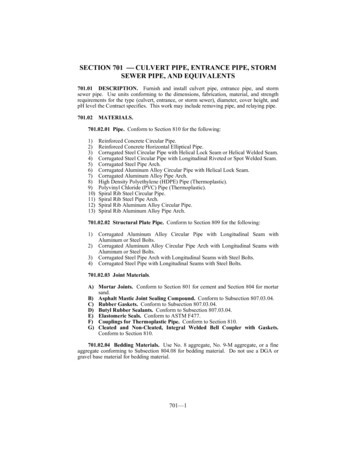
SECTION 701 CULVERT PIPE, ENTRANCE PIPE, STORMSEWER PIPE, AND EQUIVALENTS701.01 DESCRIPTION. Furnish and install culvert pipe, entrance pipe, and stormsewer pipe. Use units conforming to the dimensions, fabrication, material, and strengthrequirements for the type (culvert, entrance, or storm sewer), diameter, cover height, andpH level the Contract specifies. This work may include removing pipe, and relaying pipe.701.02MATERIALS.701.02.01 Pipe. Conform to Section 810 for the following:1)2)3)4)5)6)7)8)9)10)11)12)13)Reinforced Concrete Circular Pipe.Reinforced Concrete Horizontal Elliptical Pipe.Corrugated Steel Circular Pipe with Helical Lock Seam or Helical Welded Seam.Corrugated Steel Circular Pipe with Longitudinal Riveted or Spot Welded Seam.Corrugated Steel Pipe Arch.Corrugated Aluminum Alloy Circular Pipe with Helical Lock Seam.Corrugated Aluminum Alloy Pipe Arch.High Density Polyethylene (HDPE) Pipe (Thermoplastic).Polyvinyl Chloride (PVC) Pipe (Thermoplastic).Spiral Rib Steel Circular Pipe.Spiral Rib Steel Pipe Arch.Spiral Rib Aluminum Alloy Circular Pipe.Spiral Rib Aluminum Alloy Pipe Arch.701.02.02 Structural Plate Pipe. Conform to Section 809 for the following:1)2)3)4)Corrugated Aluminum Alloy Circular Pipe with Longitudinal Seam withAluminum or Steel Bolts.Corrugated Aluminum Alloy Circular Pipe Arch with Longitudinal Seams withAluminum or Steel Bolts.Corrugated Steel Pipe Arch with Longitudinal Seams with Steel Bolts.Corrugated Steel Pipe with Longitudinal Seams with Steel Bolts.701.02.03 Joint Materials.A) Mortar Joints. Conform to Section 801 for cement and Section 804 for mortarsand.B) Asphalt Mastic Joint Sealing Compound. Conform to Subsection 807.03.04.C) Rubber Gaskets. Conform to Subsection 807.03.04.D) Butyl Rubber Sealants. Conform to Subsection 807.03.04.E) Elastomeric Seals. Conform to ASTM F477.F) Couplings for Thermoplastic Pipe. Conform to Section 810.G) Cleated and Non-Cleated, Integral Welded Bell Coupler with Gaskets.Conform to Section 810.701.02.04 Bedding Materials. Use No. 8 aggregate, No. 9-M aggregate, or a fineaggregate conforming to Subsection 804.08 for bedding material. Do not use a DGA orgravel base material for bedding material.701—1
701.02.05Backfill Materials.A) Granular Backfill.1)2)3)4)For Reinforced Concrete Pipe. Use size No. 2, 23, 3, 357, 4, 467, 5, 57, 67,68, 78, 8, or 9M aggregate or material conforming to AASHTO M 145 Alor A3 material with a maximum plasticity index of 10 (see table below).Limit rock fragments to a 3-inch maximum size.For Corrugated Metal Pipe. Use size No. 2, 23, 3, 357, 4, 467, 5, 57, 67, 68,78, 8, or 9M aggregate or material conforming to AASHTO M 145 Al orA3 material with a maximum plasticity index of 10 (see table below). Limitrock fragments to a size that does not exceed the corrugation width.For Thermoplastic Pipe. Use size No. 5, 57, 67, 68, 78, 8, or 9M aggregateor material conforming to AASHTO M 145 Al or A3 material (see tablebelow). Limit rock fragments to a 1.5-inch maximum size. For corrugatedpipe, limit rock fragments to a size that does not exceed the corrugationwidth or 1.5 inches, whichever is least.For Structural Plate Pipe. Use Structure Granular Backfill conforming toSection 805.A1 and A3 Characteristics(1)Sieve Analysis: Percent passing No. 10A1A3——Percent passing No. 4050 maxPercent passing No. 20025 maxPlasticity index of material passing No. 406 max(1)For a complete description see AASHTO M 14551 min10 max—B) Flowable Fill. Conform to Subsection 601.03.03 B).701.02.06 Embankment. Conform to Subsection 206.701.02.07 Geotextile Fabric Material. Use Type IV fabric with a minimum widthof 36 inches conforming to Section 843.701.02.08 Asphalt Material for Coating. Conform to Section 806.701.03CONSTRUCTION.701.03.01 Pipe Foundations. Take soundings for the pipe foundation design at theinlet and outlet, and along the grade line of each culvert on 20 foot intervals. Take thesoundings to a depth of 1/2 inch per foot of embankment height (measured from the crownof the pipe to the maximum fill height) or 24 inches, whichever is greater.Where rock foundations (ledge rock, gravel, hardpan or other unyielding material) areencountered or known to exist within the limits specified, prepare the foundationaccording to the Standard Drawings.Where unstable (soft) foundations are encountered at the established grade line,remove the material that the Engineer determines is unstable and replace with a materialconforming to Subsection 701.02.04. The Department will determine the depth of theover excavation by a soils investigation for the specific structure. Wrap the replacementmaterial in geotextile fabric when backfilling.701.03.02 Trench Conditions. .Install all pipe in excavated trenches. Where anembankment condition exists, excavate the trench only after constructing the embankment701—2
according to Section 206 to an elevation equal to, or greater than, the minimum coverheight of the pipe.701.03.03 Pipe Bedding.A) Reinforced Concrete Pipe.Drawings and this section.1)2)Construct bedding according to the StandardType 1 Installation. When working on a rock foundation, place bedding to adepth of 6 inches or equal to Bc/12, the pipe diameter in inches divided by12, whichever is greater. For all other foundations, place a minimum of 4inches of bedding. Shape the bedding to conform to the invert shapethroughout the entire width and length of the proposed structure. Compactthe bedding, but leave the center third of the pipe diameter (Bc/3)uncompacted. Place and compact additional bedding material in lifts 6inches or less to an elevation of 0.30 the culvert diameter.Type 4 Installation. When working on a rock foundation, place bedding to adepth of 6 inches or equal to Bc/12, the pipe diameter in inches divided by12, whichever is greater. For all other foundations, place a minimum of 4inches of bedding.B) Corrugated Metal, Thermoplastic, and Structural Plate Pipe. Place andcompact bedding to provide 4 inches of bedding below the outside invert of thepipe after shaping. Shape the bedding to conform to the invert shape throughoutthe entire width and length of the proposed structure. Place and compactadditional bedding material in lifts 6 inches or less to an elevation of 0.30 theculvert diameter.701.03.04 Pipe Hauling, Handling, and Installation. Furnish a copy of themanufacturer’s handling and installation procedures to the Engineer before beginningwork. Ensure that pipe structures do not sustain damage during loading, unloading,placement on the bedding, compaction of the backfill, by movement of excessively heavyequipment over the fill, or by any other forces that may cause damage. Repair or replacedamaged structures as the Engineer directs. Remove and replace any structure that is notconstructed to true alignment or shows undue settlement after installation, or is otherwisedamaged, without additional compensation.A) Reinforced Concrete Pipe. Install the pipe beginning at the outlet end of theculvert, with the bell or groove end laid upgrade. Extend successive spigot ortongue ends fully into each adjoining bell or groove. When the pipe includesmarkings to designate the top and bottom, lay the pipe so the mark is less than 5degrees from the vertical plane throughout the longitudinal axis of the pipe.Cover all lift holes after installing the pipe by the following:1)2)3)Coat an area 8 inches or wider than the holes on the outside of the pipe withan asphalt coating material;Place a piece of sheet metal 4 inches or wider than the holes and shaped toconform to the outer pipe diameter over each hole; andApply an additional coating of asphalt material over the entire area ofpreviously applied metal. When desired, use precast lift hole plugs insteadof the asphalt and sheet metal.B) Corrugated Metal Pipe.1)Asphalt Coating. Apply according to AASHTO M-190.701—3
2)3)Transporting and Handling. Transport and handle coated pipe usingequipment and methods that prevent damage to the coating. When storingpipe on the project, keep it supported above the ground using woodentimbers or pallets. Repair minor damage to exterior and interior coatingwith asphalt coating material according to AASHTO M 243 or as theEngineer directs before installing the pipe. Repair significant damage andcoating deficiencies at the pipe fabrication site as the Engineer directs.Significant damages include spalled coating on the interior of the pipe,uncoated areas due to manufacturing error, and insufficient coatingthickness on the interior or exterior of the pipe.At all times during construction, use every precaution to preventdamage to the protective coating. Do not allow any metal tools or heavyobjects to unnecessarily come in contact with the finished coating. Repairany damage to the protective coating from any cause during installation andbefore final acceptance as the Engineer directs.Installing. Assemble according to the manufacturer’s instructions. Install inthe bed starting at the downstream end. When using corrugated metal pipewith paving material, install the pipe with paving material along the bottomcenterline or flowline. Construct struts and vertical elongation of corrugatedmetal pipe as specified in the Plans. Remove the struts only after completingthe embankment over the structure.C) Thermoplastic Pipe.Handle thermoplastic pipe according to themanufacturer’s recommendations.Provide a manufacturer’s technicalrepresentative to assist in the installation of the pipe when the Engineer requests.D) Structural Plate Pipe. Install the pipe according to the manufacturer'sspecifications and installation procedures. When the Engineer requests, providea manufacturer's technical representative to assist in pipe construction. Do notplace backfill until all plates in a ring are complete and all bolts in the structureare tightened.701.03.05 Joints. Provide soil tight joints. Wrap all pipe joints with a geotextilefabric when their inner diameters are 54 inches and greater.A) Reinforced Concrete Pipe. Use only one type of jointing materials systemthroughout each single structure. Construct joints for reinforced concrete pipewith one of the following options.1)2)Mortar Joints. Use a mixture containing one part cement and 2 parts sand.Use enough water, not exceeding 5 1/2 gallons per sack of cement, toproduct a stiff, workable mortar. Thoroughly clean and wet the ends of thepipe before joining them. Place the mortar in the lower half of the bell orgroove section that has been laid, and apply mortar to the upper half of thespigot or tongue of the pipe that is being laid. Insert the spigot or tongue inthe bell or groove of the pipe already laid, pull the joint tight, and ensurethat the inner surfaces of the abutting sections are flush and even. Afterlaying a section of the pipe and before laying the succeeding section,thoroughly plaster the lower portion of the bell or groove of the precedingsection on the inside with mortar to such a depth to ensure a smooth jointbetween the abutting sections. Fill the remainder of the joint flush withmortar. Finish the inside of the joint and wipe smooth around the fullcircumference. After the initial set, protect the mortar from air and sun witha burlap cover, or permanently backfill.Asphalt Mastic Joints. Immediately before installation, apply the asphaltmastic joint sealing compound to the ends of the pipe section in the samemanner as mortar joints except precoat all joining surfaces. Precoat with the701—4
3)4)manufacturer’s recommended primer or an approved emulsified asphalt.Apply enough sealer to extrude a bead of the compound from the joint onthe inside and outside of the pipe when completely meshed. Remove excessmaterial to form a smooth, flush joint.Rubber Gaskets. In addition to the requirements of Subsection 701.02, use apipe section conforming to AASHTO M 315.Use the gasketmanufacturer’s recommended cement and lubricant. Snugly fit the rubbergasket in the beveled surface of the tongue and groove ends of the sectionsto form a flexible seal under all conditions of service.Butyl Rubber Sealants. In addition to the requirements of Subsection701.02, use pipe with a joint design conforming to AASHTO M 198.When a joint is located 12 feet or less from the outlet on a 3:1 or steeperslope, provide a tied joint according to the Standard Drawings.B) Corrugated Metal Pipe.Construct joints using a band with annularcorrugations and a bolt, bar and strap connection. Use a minimum nominal bandwidth of 12 inches for all pipe diameters 54 inches and smaller. Use a two-pieceband with a minimum nominal width of 20 inches for all pipe diameters greaterthan 54 inches. Manufacture the band from the same base materials as the pipe.The pipe bands may be up to two gauges lighter than the pipe it is joining, with aminimum gauge thickness of 16. The Department may allow dimple bandconnections for field cut pipe. Install the connecting bands according to themanufacturer's written recommendations.C) Thermoplastic Pipe. Use an integral bell and spigot type with elastomeric sealjoints. When a joint is located 12 feet or less from the outlet on a 3:1 or steeperslope, use a cleated integral bell locking joint or a standard coupling aided bytwo #14 by 2-inch galvanized sheet metal screws inserted through the couplinginto the corrugation crest 2 inches apart circumferentially at the bell and spigotcoupler’s quarter points.701.03.06 Initial Backfill. Locate a suitable backfill source for each project. Forbackfill containing soils, have an AASHTO accredited lab classify the material, run astandard proctor, and certify that the material conforms to the specified granular material.Keep the material certification on file and available to the Engineer upon request.Place the backfill material in a trench condition as the Contract specifies. Use 6-inchlifts and ensure the backfill is compacted to not less than 95 percent of the maximumdensity as determined according to KM 64-511.When the top of the pipe is within one pipe diameter of the subgrade, backfill withflowable fill to an elevation of one foot above the pipe from the outside edge of shoulderor back of curb to outside edge of shoulder or back of curb as applicable. When installingunder existing pavement, backfill with flowable fill to the subgrade elevation.When granular backfill is used, the surrounding conditions are not similar ingradation, and the pipe is located within the area bounded by the centerline and a distance25 feet outside the edge of shoulder or back of curb, as applicable, wrap the bedding andgranular backfill in geotextile fabric. The Department will not require geotextile fabric forentrance pipe. When geotextile fabric is required according to this section or theEngineer’s direction, install according to Section 214.When the Contract specifies, perform quality control testing to verify compactionaccording to KM 64-412. The Department may verify the density results at any time ofthe duration of the project.A) Reinforced Concrete Pipe.1)Type 1 Installation. When the top of the pipe is not within one pipediameter of the subgrade, backfill with granular backfill, additional bedding701—5
2)material, or flowable fill from the top of the bedding to an elevation equal to1/2 the pipe diameter, and either granular backfill, flowable fill, orembankment material in 6-inch lifts to an elevation of one-foot above thepipe.Type 4 Installation. Backfill from the top of the bedding with granularbackfill, flowable fill, or embankment material in 6-inch lifts to an elevationof one-foot above the pipe. The Department will allow Type 4 installationsfor median drains and pipe installations located 35 feet or more from theedge of shoulder, back of curb, or any paved surface.B) Corrugated Metal, Thermoplastic, and Structural Plate Pipe. When the topof the pipe is not within one pipe diameter of the subgrade, backfill with eithergranular backfill or flowable fill to an elevation at least one foot above the top ofthe pipe.701.03.07 Construction Loads. Do not allow construction equipment or traffic totravel over the top of the structure material until the fill is compacted to a minimum depthof 48 inches over the top of the structure. The Engineer may require temporary coverwhere the final grade is less than 48 inches. The Engineer may raise but will not lower theminimum cover based on the pipe manufacturer’s recommendations.701.03.08 Testing of Pipe. The Engineer will visually inspect all pipe. TheDepartment may require camera or mandrel testing, KM 64-114, for any pipe whendeflection, cracking, joint faulting, or any other interior damage is suspected. If the pipeshows damage, repair or replace as the Engineer directs. If the pipe shows deflection of10 percent or greater, remove and replace the pipe. If the pipe shows deflection greaterthan 5 percent but less than 10 percent, the Department will allow the pipe to remain inplace at a reduced unit price. Do not pave over any pipe until inspection and any requiredtesting is completed. When paving will not be delayed by the wait, test pipe 30 days ormore after backfilling is completed.701.03.09 End Structures. Construct anchors, concrete headwalls, and other endstructures specified in the Plans according to Section 610, Section 710, and the StandardDrawings.701.03.10 Extensions to Existing Culvert Pipe and Entrance Pipe. Construct pipeextensions for culvert pipe, entrance pipe, and equivalent pipe arches according to thissection and the Contract. Remove the necessary portions of the existing structure toprovide a neat junction with the extension. Do not damage the portion that is to remain inservice. Remove all silt and debris that has accumulated in the remaining portion of thestructure for a distance back equal to twice the pipe diameter or as the Engineer directs.701.03.11 Removing Pipe, Removing and Relaying Pipe. Remove all pipedesignated for removal in the Contract. Safely store all reusable pipe. Restore or replace,any pipe designated for reuse that incurs damage or destruction through faulty handling.Relay all removed pipe the Contract designates to be relayed. Where pipe is not to berelayed, fill the area to the existing ground line according to 207.03.The Department will retain ownership of reusable pipe that is not to be relaid in areason the project. Unless the Engineer directs otherwise, deliver all reusable pipe not relayedon the project to the designated maintenance facility in the county where the project islocated. Take ownership of and remove from the project all pipe that is not designated forreuse or salvage.701.04MEASUREMENT.701.04.01 Culvert Pipe. The Department will measure the quantity in linear feet701—6
from end-to-end along the bottom or pipe invert of the installed structure. The Departmentwill include bends, elbows, crosses, tees, reducers, laterals, wyes, and other shapes in thepipe lengths measured. The Department will not measure joint materials and beddingmaterials for payment and will consider them incidental to this item of work. TheDepartment will not measure replacement of damaged pipe for payment and will considerit incidental to this item of work. The Department will not measure for payment theproviding of a manufacturer’s technical representative to assist in the construction of thepipe and will consider it incidental to this item of work.701.04.02 Culvert Pipe Equivalent. Culvert Pipe Equivalent includes ellipticalculvert pipe and culvert pipe arches. The Department will measure the quantity in linearfeet according to Subsection 701.04.01.701.04.03 Entrance Pipe. The Department will measure the quantity in linear feetaccording to Subsection 701.04.01.701.04.04 Entrance Pipe Equivalent. Entrance Pipe Equivalent includes ellipticalentrance pipe and pipe arches. The Department will measure the quantity in linear feetaccording to Subsection 701.04.01.701.04.05 Storm Sewer Pipe. The Department will measure the quantity in linearfeet according to Subsection 701.04.01.701.04.06 Storm Sewer Pipe Equivalent. Storm Sewer Pipe Equivalent includeselliptical storm sewer pipe and storm sewer pipe arches. The Department will measure thequantity in linear feet according to Subsection 701.04.01.701.04.07 Testing. When testing is performed due to a disagreement with a visualinspection and the Department is in error, the Department will measure the quantity asExtra Work according to Subsection 104.03.701.04.08 Geotextile Fabric, Type IV. The Department will measure the quantityin square yards.701.04.09 Flowable Fill. The Department will not measure the quantity for paymentand will consider it incidental to the pipe bid item. When the Engineer determines that itis necessary and to the Department’s benefit to excavate beyond the typical excavationlimits shown in the Standard Drawings, the Department will measure the quantity offlowable fill required for backfill outside the typical excavation limits as Extra Work.701.04.10 Embankment-In-Place. The Department will measure the quantitywhere there is unstable foundation material in excess of 3 times the width of outsidediameter of the pipe or the width of the outside diameter plus 4 feet, whichever is less, incubic yards according to Subsection 206.04.701.04.11 Roadway Excavation. The Department will measure the quantity forremoval of unstable foundation material in excess of 3 times the width of outside diameterof the pipe or the width of the outside diameter plus 4 feet, whichever is less, in cubicyards according to Subsection 204.04.When using Special Design, the Department will measure the quantity by the lengthof the trench the Contract specifies or as the Engineer directs. The Department will notmeasure backfilling the trench with bedding material for payment and will consider itincidental to this item of work.The Department will not measure any other excavation and will consider it incidentalto Culvert Pipe, Entrance Pipe, and Storm Sewer Pipe.701.04.12 Pipe Undercut. The Department will measure the quantity for removal of701—7
unstable foundation material or bedded rock in cubic yards up to a maximum of 3 timesthe width of the outside diameter of the pipe or the width of the outside diameter of thepipe plus 3 feet, whichever is less, and to a depth of up to 2 feet. The Department willmeasure the quantity at a depth of greater than 2 feet as Extra Work according toSubsection 109.04.701.04.13 Structure Excavation Unclassified. When the Engineer changes thepipe’s plan length or location and causes the required excavation to increase more than 10percent above the original average excavation per yard, the Department will measure thequantity in cubic yards according to Subsection 603.04. When the Department requires asubstantial increase in excavation, submit verification to the Engineer before startingexcavation. The Engineer will then measure the quantity of excess volume. TheDepartment will not consider the excavation of unstable material from the foundationwhen determining the percentage of material increase.701.04.14 Removing Pipe. The Department will measure the quantity in linear feetof net laying length per section. The Department will measure bends, elbows, crosses,tees, reducers, laterals, wyes, and other shapes in linear feet along the central axis of theunit. The Department will not measure furnishing and placing any borrow materialnecessary to refill the area to the original ground line for payment and will consider itincidental to this item of work. When the Department retains ownership, the delivery ofthe pipe to the designated maintenance facility will not be measured for payment and isconsidered incidental to this item of work.Unless design quantities are included in the Contract, the Department will notmeasure pipe within the typical section for payment and will consider it incidental toroadway excavation.701.04.15 Removing and Relaying Pipe. The Department will measure thequantity according to Subsection 701.04.01. The Department will not measure sectionsthat are damaged or broken for payment and will consider them incidental to this item ofwork. The Department will not measure furnishing and placing any borrow materialnecessary to refill the area to the original ground line for payment and will consider themincidental to this item of work. When the Department retains ownership, the delivery ofthe pipe to the designated maintenance facility will not be measured for payment and isconsidered incidental to this item of work.701.05 PAYMENT. The Department will make payment for the completed andaccepted quantities under the 022030131001312(1)Pay ItemCulvert Pipe, SizeCulvert Pipe Equivalent, SizeEntrance Pipe, SizeEntrance Pipe Equivalent, SizeStorm Sewer Pipe, SizeStorm Sewer Pipe Equivalent, SizeFabric-Geotextile, Type IV for PipeEmbankment-In-PlaceRoadway ExcavationPipe UndercutStructure Excavation, UnclassifiedRemove PipeRemove and Relay PipePay UnitLinear FootLinear FootLinear FootLinear FootLinear FootLinear FootSquare Yard(2)See Subsection 206.05See Subsection 204.05Cubic Yard(1)See Subsection 603.05Linear FootLinear FootThe unit price is 20.00 per cubic yard for pipe undercut 2 feet in depth or less.The Department will pay for pipe undercut exceeding a depth of 2 feet, as specifiedin Subsection 109.04.701—8
(2)The unit price is 2.00 per square yard for Fabric-Geotextile, Type IV for PipePIPE DEFLECTION DETERMINED BY CAMERA TESTINGAmount of Deflection (%)Payment0.0 to 5.05.1 to 7.57.6 to 8.58.6 to 9.910 or greater100% of the Unit Bid Price75% of the Unit Bid Price50% of the Unit Bid Price25% of the Unit Bid PriceRemove and ReplacePIPE DEFLECTION DETERMINED BY MANDREL TESTINGAmount of Deflection (%)Payment0.0 to 5.0100% of the Unit Bid Price5.1 to 9.950% of the Unit Bid Price10 or greaterRemove and ReplaceThe Department will consider payment as full compensation for all work requiredunder this section.701—9
SECTION 702 SLOTTED DRAIN PIPE702.01 DESCRIPTION. Furnish and place slotted drain pipe of the specified size andwall thickness, at the locations specified in the Plans or designated by the Engineer.702.02MATERIALS.702.02.01 Slotted Drain Pipe. Conform to Subsection 810.04.05.702.02.02 Coupling Bands.manufacturer.Provide coupling bands recommended by the702.03 CONSTRUCTION. Conform to Section 701.03 and the Standard Drawings forexcavation of the pipe trench, pipe placing, and backfill.Do not begin installing the slotted drain pipe until paving of the traffic lanes adjacentto the pipe has been completed at the location where the pipe is to be installed.Before backfilling, plug the upgrade end of the slotted drain pipe with a metal cap orby other methods the Engineer approves.During the backfilling operations and paving operations adjacent to the slot, cover theslot to prevent infiltration of material into the pipe, and do not damage the slotted drainpipe. Remove foreign material that enters the pipe, and repair any damage to the slotteddrain pipe to the satisfaction of the Engineer, at no expense to the Department.702.04MEASUREMENT.702.04.01 Slotted Drain Pipe. The Department will measure the quantity in linearfeet. The Department will not measure structure excavation, backfill, plugging, removalof foreign material, or coupling bands for payment and will consider them incidental tothis item of work.702.05 PAYMENT. The Department will make payment for the completed andaccepted quantities under the following:Code00980-00985Pay ItemSlotted Drain Pipe, SizePay UnitLinear FootThe Department will consider payment as full compensation for all work requiredunder this section.702—1
SECTION 703 SLOPE PROTECTION AND CHANNELLINING703.01 DESCRIPTION. Furnish and place the specified material for a protectivecovering for slopes or linings in channels and ditches, according to the Contract or as theEngineer directs. Slope protection includes the following types: Reinforced ConcreteSlope Wall, Cyclopean Stone Riprap, and Crushed Aggregate Slope Protection. Channellining includes the following types: Class IA (mattress units), Class II, Class III, and ClassIV (prepared from rock excavation).703.02MATERIALS.703.02.01 Concrete. Conform to Subsection 601.02 and 601.03.703.02.02 Steel Reinforcement. Conform to Section 811.703.02.03 Coarse Aggregate. Conform to Section 805.703.02.04 Fine Aggregate. Conform to Section 804, natural sand.703.02.05 Joint Material. Conform to Section 807, preformed joint filler.703.02.06 Drain Pipe. Conform to Section 810.703.02.07 Mattress Units for Channel Lining Class IA. Conform to Section 813.703.02.08 Anchor Bars for Channel Lining, Class IA. Use Grade 40 or bettersteel reinforcing bars conforming to the dimensions shown on the Standard Drawings.The Engineer will base acceptance of the anchor bars on visual inspection.703.02.09 Geotextile Fabric. Use Type I fabric conforming to Section 843.703.03CONSTRUCTION.703.03.01 Slope Protection.A) General. Do not allow slopes on which protection is placed to be steeper thanthe natural angle of repose. Shape the slopes to the slope and contour indicatedor as the Engineer directs. Use slope templates in determining the slope. Bringdepressions to the required slope line with fill material moistened and compactedas the Engineer directs.Unless solid rock is encountered, begin all slope protection, except crushedaggregate slope protection, in a trench 2 feet below the natural ground. Wheresolid rock is encountered, stop the lower terminus of the slope protection at thesolid rock line unless the Engineer directs otherwise.Unless solid rock is encountered, underlay cyclopean stone riprap, crushedaggregate slope protection and all classes of channel lining with geotextile fabric.B) Reinforced Concrete Slope Wall. Use 6-inch slope walls on slopes 1/4 to oneor flatter.Construct porous aggregate underdrains at the location o
Furnish and install culvert pipe, entrance pipe, and storm sewer pipe. Use units conforming to the dimensions, fabrication, material, and strength requirements for the type (culvert, entrance, or storm sewer), diameter, cover height, and pH level the Contract specifies. This work may include removing pipe, and relaying pipe. 701.02 MATERIALS .
