Transcription
2015 Minnesota Plumbing CodeWater Pipe Sizing Workshop
2015 Minnesota Water Pipe Sizing WorkshopWater Pipe SizingImportant TablesCopyright 2016 IAPMO1
2015 Minnesota Water Pipe Sizing WorkshopCopyright 2016 IAPMO2
2015 Minnesota Water Pipe Sizing WorkshopCopyright 2016 IAPMO3
2015 Minnesota Water Pipe Sizing WorkshopSteps for Sizing Water PipingWater Pipe Sizing ProcedureStep 1 Using Table 610.4, find the correct Pressure Range and Length Table to use.Step 2 The street service/meter and the building supply must be sized first. This step establishes the largest pipe size required for the building.Step 3Step 4 Starting at the most remote cold water outlet in the system, size the main line backtowards the meter, adding in the demand for each branch until the main line sizeequals the established building supply size. At this point the main line sizing is completed. (Attention must be given to the location of the Water Heater supply branchconnection to the main line) Size each branch and fixture supply. (Stay in same Length Column)Determining Fixture LoadsCopyright 2016 IAPMO4
2015 Minnesota Water Pipe Sizing WorkshopWater Pipe Sizing Example – Private UseDirections: Identify the number of fixture units each numbered pipe segment and determinethe correct sizing. The relevant tables needed for these calculations are provided on theprevious pages. Your work table is on the following page.Copyright 2016 IAPMO5
2015 Minnesota Water Pipe Sizing 142944153045FixtureUnitsPipeSize46474849Copyright 2016 IAPMO6
2015 Minnesota Water Pipe Sizing WorkshopWater Pipe Sizing ProblemDirections: Identify the number of fixture units each numbered pipe segment and determinethe correct 51525616267172781828919291020Copyright 2016 IAPMOFixtureUnitsPipeSize7
2015 Minnesota Water Pipe Sizing WorkshopWater Pipe Sizing Problem 2Directions: Identify the number of fixture units each numbered pipe segment and determinethe correct sizing. Your work table is located on the following page.Copyright 2016 IAPMO8
2015 Minnesota Water Pipe Sizing WorkshopPipeSectionFixtureUnitsPipe SizePipeSectionFixtureUnitsPipe SizePipeSectionFixtureUnitsPipe 57132843142944153045Copyright 2016 IAPMOFixtureUnitsPipe Size9
2015 Minnesota Plumbing Code – DWV Sizing WorkshopDrain Waste and Vent Sizing - ExampleDirections: Identify the number of fixture units each numbered pipe segment and determinethe correct sizing. The relevant tables needed for these calculations are provided on thefollowing pages.Copyright 2017 IAPMO1
2015 Minnesota Plumbing Code – DWV Sizing WorkshopImportant TablesCopyright 2017 IAPMO2
2015 Minnesota Plumbing Code – DWV Sizing WorkshopCopyright 2017 IAPMO3
2015 Minnesota Plumbing Code – DWV Sizing WorkshopDWV Sizing WorksheetPipeSectionFixtureUnitsPipe SizePipeSectionFixtureUnitsPipe 24102511261227132814291530Copyright 2017 IAPMOFixtureUnitsPipe Size4
2015 Minnesota Plumbing Code – DWV Sizing WorkshopDWV Sizing ProblemDirections: Identify the number of fixture units each numbered pipe segment and determinethe correct sizing.Pipe SectionFixture UnitsPipe SizeABCDEFGCopyright 2017 IAPMO5
2015 Minnesota Plumbing Code – DWV Sizing WorkshopDWV Sizing ExerciseDirections: Identify the number of fixture units each numbered pipe segment and determinethe correct sizing.Sizing Notes: Building is Public Use Water closet are 1.6 GPM flush-o-meter valves Urinals are 1 GPF Floor drains are 2” emergency use only Bottom floor fixtures are below the crown level of the sewer Sewage ejectors are 20GPM and operate individually Back to back water closet drain through an approved double fixture fitting.Copyright 2017 IAPMO6
2015 Minnesota Plumbing Code – DWV Sizing WorkshopDWV Sizing WorksheetPipeSectionFixtureUnitsPipe SizePipeSectionFixtureUnitsPipe SizePipeSectionFixtureUnitsPipe 57132843142944153045Copyright 2017 IAPMOFixtureUnitsPipe Size7
2015 Minnesota Plumbing Code – DWV Sizing WorkshopCopyright 2017 IAPMO8
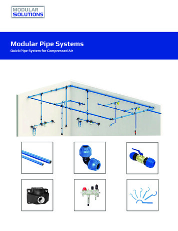
Emerging Technology in the Plumbing and Mechanical IndustriesOverview Let’s examine new technologies in the Plumbing and MechanicalIndustry! Discuss how these new products affect our bottom line Can sustainability be achieved without causing unintendedconsequences to health and safety? How will we approach these changes?Emerging Technologies in Plumbing and Mechanical SystemsComplicated Times Water ConservationEnergy ConservationSustainabilityComforts and ExpectationsNew Laws and RegulationsHealth and Well BeingNew Product InspectionsWhen we see new innovative products and installations on the jobsitewe do one of three things: I’ve never seen that – Red Tag it!!
New Product Inspections I’ve never seen that – COVER IT UP!!301.2 Alternate Materials and Methods ofConstructionEquivalencyNothing in this code is intended to preventthe use of systems, methods, or devices ofequivalent or superior quality, strength, fireresistance, effectiveness, durability, and safetyover those prescribed by this code. Technicaldocumentation shall be submitted to theAuthority Having Jurisdiction to demonstrateequivalency. The AHJ shall have the authorityto approve or disapprove the system, method,or device for the intended purpose.New Product Inspections I’ve never seen that – tell me more, show me how this works and isin compliance with the code!Let’s look at some new plumbing product innovations .“Reinvent the Toilet” Challenge
The Reinvent the Toilet Challenge aims to create atoilet that:– Removes germs from human waste and recoversvaluable resources such as energy, clean water, andnutrients.– Operates “off the grid” without connections to water,sewer, or electrical lines.– Costs less than US .05 cents per user per day.– Promotes sustainable and financially profitablesanitation services and businesses that operate inpoor, urban settings.– Is a truly aspirational next-generation product thateveryone will want to use—in developed as well asdeveloping nations.Royal Society of theArts The Caltech system isan onsiteelectrochemicalwastewater treatmentand recycling unit thatcan be powered bysolar panelsWellbeing Toilet an improved design of the toilet (e.g. sit type, squat type, hybrid)that creates a positive everyday experience for someone with adisability or impairment an intuitive flush operation mechanism requiring minimalinstructions ideas to minimize misuse and abuse of the toilet e.g. theft andvandalism designs which improve personal safety, particularly for vulnerableusers e.g. females, older people intuitive design that encourages minimal hand contact and goodhygiene designs which focus on privacy e.g. aural, visual and odour an improved design in terms of cleaning and maintenance
The “IOTA”
Urinal Video GameAnalyzer SensorUrinal Alcohol Level Detector
Thermostatically Activated Flow Control Valve Self actuating thermostatic balancing valve controls temperature
Thermostatically and ContinuouslyAdjusting the Return Flow Rate tomaintain water temperatureLocated at theend of each hotwater supplybranchdownstream ofthe last fixture.Controlling theReturn WaterFlow where atraditionalbalancing valveor circuit setterwould be located. Thermostatically Self-Adjusting the ReturnWater Flow Rate to maintain the watertemperature. Increasing the Return Flow of water that Coolsbelow the specified set-point. Reducing the Return Flow of water that is stillHot. Conserving Energy and Water by only reheatingwater that needs heating, and minimizing waterwaste from waiting for hot water to get to the tap.Tankless balancing valvescompensate for awide variety ofchanging variablesin a DHW system
Proximity SensingWater Conservation & ReuseWhat ways does your area conserve, capture and reuse water?
Water Conservation & ReuseWe are continually finding new ways to reuse and recycle waterWater Conservation & ReuseGreywater Treatment
Let’s look at some enginnering innovations . What about making water out of thin air?
KEMPER Potable Water Hygiene System67Siphonic Roof DrainsGrease Interceptor Bioremediation
CleanBlu How it worksSmart Phone App based Monitoring and Control (24/7)BlueBot Element (Aerobic) to remediate wastewater component,stabilize biofuel (preventing hydrolysis) and biologically reducesulfur and phosphorus, heavy metals and other contaminantsSuper Energy Efficient Components(50 Watts/element - 3.60/month)Custom Microbial blendsWhy CleanBlu ?CleanBlu solutionShredder Mix System for Grease InterceptorsCurrent solutionFirst and only commercially and technically viable method to convertbrown-grease into BiodieselAutomated process, email notification when biofuel is ready forcollection and transportationAllows complete conversion of FOG into Biodiesel
Radiant Heating Ceiling DrywallLet’s look at some new mechanical innovations .
Contour Crafting3D PrintingContour Crafting3D PrintingCharles Darwin“It is not the strongest of the species thatsurvives, nor the most intelligent that survives. Itis the one that is most adaptable to change.In the struggle for survival, the fittest win out atthe expense of their rivals because they succeedin adapting themselves best to theirenvironment.”Discussion Any new technologies your jurisdiction or demographic is seeing?Questions?
12/15/2017“Is Our Water Supply Vulnerableto Terrorism?How It Can Be Protected.”1Daniel W. Rademacher Own and operate Plumbing Code and Design Consulting, LLCwww.pcdconsultingservices.com Employed 6 years as Plumbing/Mechanical Designer III for a national A & E firm. Served as the Chief Plumbing/Mechanical Inspector for the State of Montana for8 years. Served as a Plumbing/Mechanical Inspector for 2 years. Licensed Plumber. UA Journeyman & Apprentice Instructor. ASSE Instructor for Backflow Assemblies Testing and Cross ConnectionInspection and Surveys. Serve on the ASSE Product Standards Committee and ProfessionalQualifications Standards Committee NITC Med-Gas Certifications and Inspections. American Society of Plumbing Engineers. National Seminar Instructor for IAPMO. Serve on the IAPMO Education and Training Committee. 2014 IAPMO “Industry Person of the Year” Award Recipient. IAPMO Certified Plumbing/Mechanical Inspector2BREAKS AND CELL PHONES PLEASE FEEL FREE TO USE THE BATHROOM AT ANYTIME. PLEASE TURN YOUR CELL PHONE TO SILENT MODE.31
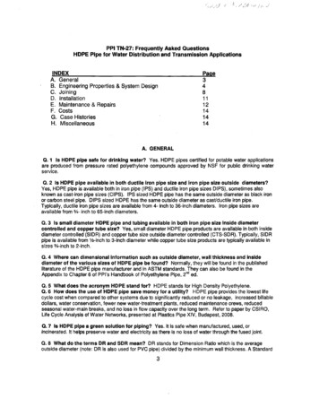
12/15/2017U.S. Drinking Water Infrastructure Most water supply systems in the United States consist of the commonelements of a source(s), a treatment facility and a distribution system. Distribution system infrastructure is generally the major asset of a waterutility, even though most of the components are either buried or locatedinconspicuously. Water is transported from its source or sources to various consumers andthe system is designed to operate both consistently and economically, andto deliver water in sufficient quantity, of acceptable quality, and atappropriate pressure. In general, to continuously and reliably move water between a source and acustomer, the system would require storage reservoirs or tanks, and anetwork of pipes, pumps, valves, and other appurtenances. This infrastructure is collectively referred to as the drinking water distributionsystem (WDS).5System Design and Operation The branch, grid, or loop represents the three basic configurations for mostWDSs. A branch system is similar to that of a tree branch with smaller pipesbranching off larger pipes throughout the service area. This type of system is most frequently used in rural areas, and the water has onlyone possible pathway from the source to the consumer. Grid and loop systems are similar, except that a loop system typically contains alarger diameter primary transmission mains that surround the distribution area,contributing water supply within the grid from different directions. Grid and loop systems are the most widely used configurations in large municipalsystems and consists of interconnected pipe loops throughout the area to beserved. In this type of system, there are several pathways that the water canfollow from the source to the consumer. Transmission water mains are typically 20 to 24 inches in diameter or larger.Dual-service mains that serve both transmission and distribution purposes arenormally 12–20 inches in diameter.62
12/15/2017 Distribution mains are usually 6–12inches in diameter and located in everystreet. Service lines are typically 1 inch indiameter. Single family residences arecommonly served by 3/4 inch servicelines; While apartment buildings are largeresidences can have service lines largerthan 1 inch. Specific pipe sizes can vary depending onthe extent of the distribution system andthe magnitude of demand. Looped systems provide a high degree ofreliability should a line break occur,because the break can be isolated withlittle impact on consumers outside theimmediate area.7Key infrastructure components in a WDS include the following: Storage tanks or reservoirs Pipe network Valves Pumps Hydrants Other appurtenances, e.g., pits, manholes, blow-offs, and meters. 2.2.1.1Basic8Basic Design and Operational Philosophies A detailed understanding of ‘‘how water is used’’ iscritical to understanding WDS design and operation. Almost universally, the manner in which industrialand residential customers use water drives theoverall design and operation of a WDS. Generally, water use varies both spatially andtemporally. Besides customer consumption, a major function ofmost distribution systems is to provide adequatestandby fire-flow capacity. For this purpose, fire hydrants are installed in areasthat are easily accessible to fire fighters and are notobstacles to pedestrians and vehicles.93
12/15/2017 The ready-to-serve requirements for firefighting are governed by the NationalFire Protection Association (NFPA), which establishes standards for fire-fightingcapacity of distribution systems (NFPA 2003). In order to satisfy this need for adequate standby capacity and pressure (asmentioned earlier), most distribution systems use standpipes, elevated tanks,and large storage reservoirs. Additionally, most large distribution systems are ‘‘zoned.’’ Zones are areas orsections of a distribution system of relatively constant elevation. Zones can be used to maintain relatively constant pressures in the system overa range of ground elevations. Sometimes, zone development occurs as a resultof the manner in which the system has expanded. Supervisory Control and Data Acquisition (SCADA) systems are keycomponents in operating water distribution networks and have become standardfor all medium to large drinking water utilities.1011SCADA Systems As with society in general, the use of computer technology in water and wastewater technology has become increasingly prevalent. The computer systems for most medium to large water utilities typically includethe financial system, the Human Resource system, Laboratory InformationManagement Systems (LIMS), SCADA systems, and ComputerizedMaintenance Management Systems (CMMS). SCADA systems are generally run by the utility itself and are available on a 24 ha day, 7 days a week basis. SCADA systems are a computer-controlled type ofindustrial control system (ICS) that monitors and controls physical industrialprocesses. SCADA systems historically distinguish themselves from other ICS systems bybeing integrated into large-scale processes that can include multiple sites andlarge distances. These processes include industrial, infrastructure, and facility-based processes.124
12/15/2017A water utility SCADA system usuallyconsists of: A human–machine interface (HMI) throughwhich the human operator monitors andcontrols the process A supervisory (computer) system, gathering(acquiring) data on the process and sendingcommands (control) to the process Remote terminal units (RTUs) connecting tosensors in the process, and sending digitaldata to the supervisory system Programmable logic controllers (PLCs),which are more economical, versatile,flexible, and configurable than specialpurpose RTUs Communication infrastructure connectingthe supervisory system to the RTUs Various process and analyticalinstrumentation13Size and Distribution of U.S. Drinking Water Utilities Water utilities in the United States varygreatly in size, ownership, and type ofoperation. The Safe Drinking Water Act (SDWA1974) defines public water systems asconsisting of community water supplysystems; transient, noncommunity watersupply (TNCWS) systems; andnontransient, noncommunity water supply(NTNCWS) systems. A community water supply system servesyear-round residents and ranges in sizefrom those that serve as few as 25 peopleto those that serve several million. A TNCWS system serves areas such ascampgrounds or gas stations wherepeople do not remain for a long period oftime.14 Some utilities rely primarily on surface water supplies while others relyprimarily on groundwater. Surface water is the primary source for 22 % of the community water supplysystems, while groundwater is used by 78 % of community water supplysystems. Of the noncommunity water supply systems (both transient andnontransient), 97 % are served by groundwater. Many systems serve communities using multiple sources of supply such asa combination of groundwater and surface water sources. In a grid/looped system, the mixing of water from different sources can havea detrimental influence on water quality, including taste and odor, in thedistribution system.155
12/15/2017Vulnerable Characteristics of U.S. Water SupplySystems to Intentional Threats Water systems are vulnerable to arange of intentional threats includingphysical disruption, contamination,and cyber attack. Vulnerable implies the existence ofa threat , as ‘‘a potential adversarialintent to cause harm or damage byadversely changing the states of thesystem.’’ Similarly, again in the context ofterrorism, vulnerability is to be the‘‘manifestation of the inherent statesof a system (e.g., physical, technical,organizational, and cultural) that canbe exploited by an adversary tocause harm or damage.’’16 Vulnerable characteristics of watersystems include their physicalattributes, e.g., reservoirs, tanks,and pump stations. The distribution system itself may bevulnerable to sabotage or intentionalcontamination. The ‘‘trusted insider’’ is a potentialthreat because he or she haspresumably extensive knowledge ofthe water system and its operation,and, therefore, capability. The largest water systems, i.e.,those supporting the largestpopulations, are believed to be themost vulnerable water systems toattack.17 In addition to physical attributes, a water utility’s SCADA could bevulnerable to cyber attack, for example, turning pumps on or off, filling oremptying tanks inappropriately, or causing water hammer events. Cyber attacks could also affect the administrative side of the water systembusiness or operation creating confusion by straining already-strainedresources and possibly leading to denial of service for some or possiblyleading to compromised water quality.186
12/15/2017 An examination of published papers, reports, and studies over thepast 10–15 years illustrates the range of threats and vulnerabilitiesto water systems that have been identified by government agencies,researchers, and commercial sectors of the water community. Some specific threats and vulnerabilities are common in many of thestudies examined. For example, contaminant threats are generally identified as theprimary threat to water systems. While disruption of water service due to some type of physicaldestruction is often identified,– most studies rank such denial of service or disruption-basedattacks below those of contamination,– both in terms of magnitude of impact (cost and public health)– and the length in time of the disruption.19Physical Disruption Scenarios The President’s Commission on CriticalInfrastructure Protection (PDD 63 1998;PCCIP 1997) identified several features ofU.S. drinking water systems that areparticularly vulnerable to terrorist attack. For example, community water supplies inthe USA are designed to deliver water underpressure and generally supply most of thewater for fire-fighting purposes. Loss of water or a substantial loss ofpressure could disable fire-fighting capability,interrupt service, and disrupt publicconfidence. This loss might result from a number ofdifferent causes. Many of the major pumps and power sourcesin water systems have custom-designedequipment and in case of a physical attack itcould take months or longer to replace them.20 Sabotaging pumps that maintain flow and pressure or disablingelectric power sources could cause long-term disruption. Many urban water systems are reliant on an aging infrastructure. Temperature variations, large swings in water pressure, vibration fromtraffic or industrial processes, and accidents often result in brokenwater mains. Planning for main breaks is usually based on historical experience;however, breaks can be induced by a system-wide hammer effect,which could be caused by opening or closing major control valves toorapidly.217
12/15/2017 This could result in simultaneous main breaks that might exceed the community’s capability to respond ina timely manner, causing widespread outages. Recognizing this vulnerability, water systems have been incorporating valves that cannot be opened orclosed rapidly. However, many urban systems still have valves that could cause severe water hammer effects.Interrupting the water flow to agricultural and industrial users could have large economic consequences. For example, the California aqueduct, which carries water from northern parts of the state to the LosAngeles/San Diego area, also serves to irrigate the agricultural areas in mid-state. Pumping stations are used to maintain the flow of water.22 Loss of irrigation water for a growing season,even in years of normal rainfall, would likelyresult in billions of dollars of loss to Californiaand significant losses to U.S. agriculturalexports. Another problem associated with manycommunity water systems is the potential forrelease of chlorine to the air. Most water systems use gaseous chlorine asa disinfectant, which is normally delivered andstored in railway tank cars. Generally, there is only minimal protectionagainst access to these cars. The release of chlorine gas, whetherintentional or unintentional, could injurenearby populations.23Examples of Unintentional Contamination Pressure transient regimes are inevitable because all systems will, at some time, be started up, switched off, or undergorapid flow changes such as those caused by hydrant flushing. They will also likely experience the effects of human errors, equipment breakdowns, earthquakes, or other riskydisturbances. Intrusion occurrences in live distribution systems and observed 15 surge events that resulted in a negative pressure. Negative pressure transients can occur in the distribution system and that the intruded water can travel downstream from thesite of entry. In fact, soil and water samples were collected adjacent to drinking water pipelines and then tested for occurrence of total andfecal coliforms, Clostridium perfringens, Bacillus subtilis, coliphage, and enteric viruses. The microorganisms and enteric viruses were detected in more than 50 % of the samples examined.248
12/15/2017Milwaukee, Wisconsin, USA In 1993, Milwaukee, Wisconsin, experienced the largestwaterborne disease outbreak in documented United Stateshistory. The etiological agent was determined to be the Cryptosporidiumprotozoan. In combination with the simultaneous occurrence of frozenground conditions, recent storms resulted in high levels ofsurface water runoff while changes in the normal treatmentprotocols were being introduced were the probable causes ofthe outbreak. The source of the organism was never officially identified but itwas suspected to be caused by the cattle genotype due torunoff from pastures or possibly discharges from a sewagetreatment plant outlet two miles upstream in Lake Michigan. The Centers for Disease Control and Prevention (CDC) showedthat this outbreak was caused by Cryptosporidium oocysts thatpassed through the filtration system of one of the city’s watertreatment plants. Over the span of approximately 2 weeks, 403,000 of anestimated 1.61 million residents in the Milwaukee area (of which880,000 were served by the malfunctioning treatment plant)became ill with the stomach cramps, fever, diarrhea, anddehydration caused by the pathogen. At least 104 deaths have been attributed to this outbreak,mostly among elderly and immuno-compromised people.25Cabool, Missouri, USA Cabool, Missouri, a town of approximately 2,100 people, locatedin the Southeastern corner of Missouri, experienced a largeoutbreak of Escherichia coli during the winter of 1989–1990. The waterborne disease outbreak resulted in 243 cases, with 32hospitalizations and 4 deaths. This was the largest waterborne outbreak of E. coli O157:H7 thathad been reported in the United States at the time. A precursor model to EPANET WDS modeling software packagewas applied to examine the movement of water andcontaminants in the system. (EPANET is a public sector model that can simulate hydraulicand water quality transport of drinking water networks.) The modeling effort revealed that the pattern of illnessoccurrence was consistent with water movement patterns in thedistribution system assuming two water line breaks. It was concluded, therefore, that some disturbance in thesystem, possibly the two line breaks and simultaneous meterreplacements, allowed contamination to enter the water system. Analysis showed that the simulated contaminant movementcovered 85 % of the infected population.26Gideon Missouri, USA In 1993, the town of Gideon, Missouri,located in a rural, agricultural area, sufferedan outbreak of salmonellosis that ultimatelyaffected more than 650 people and caused 7deaths. At the time of the outbreak, Gideon had apopulation of 1,100. In early November, thetown water system had experienced a majortaste and odor event. In response, the water system wassystematically flushed on November 10. The first cases of acute gastroenteritis werereported on November 29 and diagnosed asSalmonella typhimurium. However, the outbreak investigation laterrevealed that diarrhea cases in Gideonstarted around November 12 with a peakincidence around November 20.279
12/15/2017 By early December, there was a 250 %increase in absenteeism in the Gideonschools and a 600 % increase in antidiarrheal medication sales. Over 40 % of nursing home residentssuffered from diarrhea and seven peopledied. The U.S. EPA was requested to conduct afield study by the Missouri Department ofHealth (MDOH) and the CDC in earlyJanuary of 1994. The study utilized water quality modelingto reach the conclusion that thecontamination source was bird droppingsin the city’s largest municipal tank. The tank’s hatches had severelydeteriorated leaving the surface of thewater open to contamination by roostingbirds.28Walkerton Ontario, Canada The first documented outbreak ofEscherichia coli 0157:H7 andCampylobacter spp. bacterial gastroenteritisassociated with a municipal water supply inCanada occurred in the small rural town ofWalkerton, Ontario (population 1261) in May2000. At the time of the outbreak, the town’sdrinking water w
2015 Minnesota Plumbing Code Water Pipe Sizing Workshop. 2015 Minnesota Water Pipe Sizing Workshop . Pipe Section Fixture Units Pipe Size Pipe Section Fixture Units Pipe Size Pipe Section Fixture Units Pipe Size 1 16 31 2 17 32 3 18 33 4 19 34 5 20 35 .