Transcription
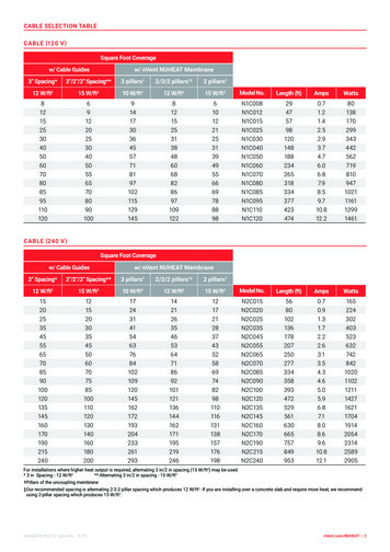
CABLE SELECTION TABLECABLE (120 V )Square Foot Coveragew/ Cable Guidesw/ nVent NUHEAT Membrane3” Spacing*3”/2”/3” Spacing**3 pillars†2/3/2 pillars†‡2 pillars†12 W/ft215 W/ft210 W/ft212 W/ft215 W/ft2Model No.Length 71021116112991461CABLE (240 V )Square Foot Coveragew/ Cable Guidesw/ nVent NUHEAT Membrane3” Spacing*3”/2”/3” Spacing**3 pillars†2/3/2 pillars†‡2 pillars†12 W/ft215 W/ft210 W/ft212 W/ft215 W/ft2Model No.Length 0201102121114271621170419142054231425892905For installations where higher heat output is required, alternating 3 in/2 in spacing (15 W/ft2) may be used.** Alternating 3 in/2 in spacing - 15 W/ft2* 3 in Spacing - 12 W/ft2†Pillars of the uncoupling membrane‡ Our recommended spacing is alternating 2-3-2 pillar spacing which produces 12 W/ft2. If you are installing over a concrete slab and require more heat, we recommendusing 2-pillar spacing which produces 15 W/ft2.Nuheat-DS-H60112-Cable-EN 18/10nVent.com/NUHEAT 2
NVENT NUHEAT CABLEElectric Floor Heating Systems Installation Guide
TABLE OF CONTENTSSECTION 1: INSTALLATION PREPARATION1.1 Installation Guidelines . 41.2 Before You Start . 51.3 Insulation & Resistance Tests . . 61.4 Insulation & Resistance Table . . 7SECTION 2: INSTALLATION2.1 Installation Planning . 82.2 nVent NUHEAT Cable & Guides . 102.3 nVent NUHEAT Thermostat Probe. 132.4 Floor Preparation: Self-Leveling Method (Recommended Method). 142.5 Floor Preparation: Thinset Mortar Method . . 152.6 Floor Preparation: Direct Method. 162.7 Floor Preparation: Wet Environment. 172.8 Floor Preparation: nVent NUHEAT Membrane. 19SECTION 3: ELECTRICAL CONNECTIONS3.1 Electrical Connections . . 21SECTION 4: THERMOSTATS & WARRANTY INFORMATION4.1 nVent NUHEAT Thermostats . 224.2 Warranty Information . 23nVent.com/NUHEAT 3
SECTION 1: INSTALLATION PREPARATION1.1INSTALLATION GUIDELINES The installation of this heating product shall be in accordance with the manufacturer’sinstructions and in accordance with the Canadian Electrical Code Part 1 or the NationalElectrical Code (US) whichever is applicable, and as permitted by the Authority HavingJurisdiction (AHJ). This equipment shall be installed only by qualified personnel who are familiar with theconstruction and operation of the apparatus and risks involved. C aution should be taken to guard against risk of electric shock, fire and bodily injuryduring the installation of this equipment. Cable should be connected to a dedicated electrical circuit. I t is mandatory to install a Class “A” GFCI or GFCI circuit breaker with each nVentNUHEAT installation. Thermostats are equipped with Class “A” GFCI protection. De-energize power circuits before installation or servicing. DO NOT USE sharp tools or power tools to clean grout lines. C able Guides and Membrane are the only accessories approved to secure Cable ontothe subfloor. I ndicate on the electrical panel which circuit is used for the Cable System. Subfloor must be prepared in accordance with ANSI specifications. Cable cannot be overlapped, crossed, cut, shortened or modified. E ntire heating portion of Cable & mechanical joint must be secured to the floor andcovered with self-leveling compound or thinset mortar. D o not install Cable in direct contact with any combustible surfaces and do not installin / on / under walls or in closets. F or concrete slab subfloors, we recommend insulating the slab prior to installing Cable.Insulation will improve the upward heat transfer from the cable to the flooring surface. The Cable System should never be installed over an expansion joint. The ambient air temperature must be above 10 C or 50 F when the Cable System isinstalled. Cable is intended for indoor embedded floor heating applications (-X) as well asin general use and wet locations (-W ) in Canada and US. M inimum spacing between cable runs for 12 W/ft2 is 3 in.For 15 W/ft2, spacing between cable runs must alternate 3 in/2 in. I f installing Cable with Membrane, minimum spacing between heating cable runs is 2.5 in(64 mm) or two pillars of the Membrane. The minimum bending radius of the heating cable is 0.5 in (12 mm). K eep ends of heating devices & kit components dry before and during installation. The sheath of this device shall not be utilized as a grounding conductor, but must bebonded to the ground. Cable is not for installation in pool and spa areas, nor outdoor use. D o not place objects directly on top of the floor that could impede/trap heat emanatingfrom the floor heating system including but not limited to flush-to-floor furniture, rubberor memory foam mats, and mattresses. These objects could cause unsafe temperaturesto be reached underneath these objects which may cause damage to the object and/orthe flooring material.4 nVent.com/NUHEAT
SECTION 1: INSTALLATION PREPARATION1.2BEFORE YOU START1.21HEATING CABLE COMPONENTSCable is comprised of:Heating Cable (red)The longest portion of Cable, this segment of Cable is strung onto the subfloor andgenerates the heat underneath your surface covering.Cold Lead (black)The non-heating segment of Cable that will run inside the wall cavity to connect to thethermostat. The cold lead is 10 ft. long.Mechanical Joint (black)The connection joint between the heating cable and the cold lead. The mechanical joint isthicker than the cold lead.1.22TOOLS Ohmeter (or multimeter) Hot glue gun (if using hot glue to secure Cable Guides ) Tools to create a groove in the subfloor (chisel or drill ) Hammer / Screwdriver1.23MATERIALS Protective plate Duct tape Industrial-grade hot glue ( if using hot glue to secure Cable Guides ) S taples, nails or #6 - ½ in screws ( if using these methods to secure Cable Guides ) Thermostat probe ( if installing a floor sensing thermostat )1.24FLOOR COVERING OPTIONSThe total combined R-values of all floor covering layers installed over Cable must notexceed R 1.5 for 12 W/ft2 and R1 for 15 W/ft2. Check with the floor covering manufacturerfor product-specific R-value ratings.nVent.com/NUHEAT 5
SECTION 1: INSTALLATION PREPARATION1.3INSULATION & RESISTANCE TESTSIf insulation or resistance tests do not pass the requirements at any point of theinstallation, halt installation immediately and contact nVent NUHEAT Technical Servicesat 1.800.778.WARM (9276).1.31INSULATION TESTTo ensure Cable is fully insulated: A cquire a digital ohmmeter (or multimeter ) with alligator clips or equivalent testingdevice. Set the ohmmeter to the appropriate setting. P lace one probe clip on the metal braid wire (ground). Place the other probe clip on theyellow/white wire (red wire for 240 V ). Confirm the reading is OL or infinity (open circuit ). R epeat these steps to check the reading between the metal braid wire (ground ) and theblack wire.1.32RESISTANCE TESTTo ensure continuity in Cable: A cquire a digital ohmmeter (or multimeter) with alligator clips or equivalent testingdevice. Set the ohmmeter to the appropriate setting. P lace one probe clip on the black wire. Place the other probe clip on the yellow / whitewire (red wire for 240 V ). C onfirm ohm reading is within 10% / - 5% of the factory reading listed on the cable tag.Record the readings in the table on page 7. I f installing a nVent NUHEAT floor-sensing thermostat, test the sensor probe.Set resistance range to 20KΩ. Probe wires should read between 8K –12K ohms. Cable must be tested before, during and after installation to validate thewarranty.6 nVent.com/NUHEAT
SECTION 1: INSTALLATION PREPARATION1.4INSULATION & RESISTANCE TABLE1.41RESISTANCE TABLERecord the resistance readings in the table below. For warranty purposes, the resistancetable must remain with the end user.CABLE RESISTANCE TABLECABLE MODEL NUMBERFACTORY MEASURED RESISTANCERESISTANCE TEST OHMS READING(BEFORE INSTALLATION)RESISTANCE TEST OHMS READING(DURING INSTALLATION)RESISTANCE TEST OHMS READING(AFTER INSTALLATION)Failure to record resistance tests in the above table will void the Cable Systemwarranty. To submit your warranty, visit nVent.com/NUHEAT and fill out the onlinewarranty card.nVent.com/NUHEAT 7
SECTION 2: INSTALLATION2.1INSTALLATION: PLANNING2.11INSTALLATION LAYOUT PLANCable may be installed 1 in to 6 in away from walls and / or fixed furniture, depending onthe square footage of the heated area.It is VERY IMPORTANT to plan the Cable installation before securing any part of thefloor heating system to the subfloor.1. U sing grid paper, draw a sketch of the room, complete with perimeter dimensions.This sketch will become the Installation Layout Plan and be referenced throughoutthe installation process.2. I ndicate the location and dimensions of counters, fixed furniture or other areas underwhich Cable cannot be installed.3. I ndicate the location and dimensions of toilet drains, heating vents or other heatingappliances. Cable should not be installed closer than 6 in from the center of toilet drains,or under the footing of the toilet.4. I ndicate the thermostat location on the Installation Layout Plan. The thermostatindicates the mechanical joint location and the start of the heating cable.5. D raw the Cable Guides on the Installation Layout Plan. Guides should generally beinstalled along the floor of two opposing walls.* To accommodate curved or angled walls and obstructions, Cable Guides maybe cut into smaller pieces before being secured to the subfloor.See Figure 2.15.*Each Cable Guide is 12” long.*FIGURE 2.15: Curved or angled cable guide installation*Not applicable if installing Cable with Membrane.8 nVent.com/NUHEAT
SECTION 2: INSTALLATION2.1INSTALLATION: PLANNING2.11INSTALLATION LAYOUT PLAN CONT.6. Draw the cable runs on the Installation Layout Plan. See Figure 2.16.ThermostatCold LeadHeating CablePerimeterCable Guides*StabilizingCable Guides*Buffer ZoneFIGURE 2.16: Installation Layout Plan Example7. D uring installation, additional “Stabilizing Cable Guides” must be inserted at 3 ft to 4 ftintervals. Determine the location of these additional guides and draw them on theInstallation Layout Plan. See Figure 2.16.*8. P redicting where the cable will end is difficult. As such, it’s important to include a “BufferZone” in the Installation Layout Plan; an area where heating is not essential (e.g. behindthe toilet, behind a door, or any other low traffic area). This “Buffer Zone” can be used toaccommodate any excess cable or remain unheated if cable is needed elsewhere. SeeFigure 2.16.Identify a “Buffer Zone” on the Installation Layout Plan. onduct insulation and resistance tests and record the resistance readingsCon page 7.*Not applicable if installing Cable with Membrane.nVent.com/NUHEAT 9
SECTION 2: INSTALLATION2.2INSTALLATION: CABLE & GUIDES2.21INSTALLING THE CABLEIf installing Cable in Membrane, please refer to installation steps in section 2.8.1. C reate a hole / notch in the wall sill plate below the thermostat electrical connection boxto allow the cold lead to be routed to the electrical box.2. I f necessary, create a small groove on the subfloor to accommodate the mechanicaljoint and / or cold lead (approximately ¼ in deep). The groove should be as close to thesill plate hole as possible.3. Secure the mechanical joint to subfloor with duct tape or hot glue.FIGURE 2.23: Secure the cold lead to the subfloor4. Secure excess cold lead to the subfloor using industrial-grade hot glue. Ensure the glue-gun tip does not touch any portion of the cold lead orheating cable.5. C able Guides are designed to snap together. See Figure 2.25. Use hot glue, staples,nails or #6 - ½ in screws to secure the Cable Guides to the subfloor per theInstallation Layout Plan. If using screws / nails / staples, use 3 to 4 screws /nails / staples per Cable Guide.FIGURE 2.25: Snap together Cable Guides10 nVent.com/NUHEAT
SECTION 2: INSTALLATION2.2INSTALLATION: CABLE & GUIDES2.21INSTALLING THE CABLE CONT.6. Install Cable according to the Installation Layout Plan. Individual runs of Cable should be spaced 3 in apart for 12 W/ft2. For 15 W/ft2,alternate spacing 3 in/2 in. Cable Guide anvils are 1 in wide.FIGURE 2.26: Install the heating cable7. E nsure individual cable runs maintains moderate tension. This will prevent the cablefrom floating during the floor covering preparation.FIGURE 2.27: Install the heating cablenVent.com/NUHEAT 11
SECTION 2: INSTALLATION2.2INSTALLATION: CABLE & GUIDES2.21INSTALLING THE CABLE CONT.8. U se duct tape, hot glue or a Cable Guide to secure the end seal of the heating cable tothe subfloor.FIGURE 2.28: Secure the end seal9. I nstall “Stabilizing Cable Guides” per the Installation Layout Plan. These additional“Stabilizing Cable Guides” will ensure the heating cables does not float during theself-levelling process. To make installation of the “Stabilizing Cable Guides” easier, flip the cable guideupside down to smoothly pass underneath the cable runs. Then flip the guidesover to secure them to the subfloor and snap the cables into place.FIGURE 2.29: Install stabilizing guides onduct insulation and resistance tests and record the resistance readingsCon page 7.12 nVent.com/NUHEAT
SECTION 2: INSTALLATION2.3INSTALLATION: THERMOSTAT PROBE2.31INSTALLING THE FLOOR-SENSING PROBEThermostat installation instructions are included with each floor-sensing thermostat.To ensure full functionality of the floor-sensing thermostat, it is vital to install thefloor-sensing probe at this point in the installation.1. S ecure the tip of the floor-sensing probe to the subfloor using duct tape.When choosing where to install the probe, ensure: The probe is away from excess temperature swings ( i.e. direct sunlight, drafts, areascovered by rugs or fixed furniture). The probe is installed a minimum of 12 in into the heated area. The probe is centered between two runs of heating cable without touching any portionof the heating cable.FIGURE 2.31: Secure the floor-sensing probe2. R oute the thermostat probe through the sill plate hole and up to the thermostatelectrical box via suitable conduit.Note: if installing a second/spare sensor, route both sensors to the electrical box.Ensure the spare sensor is away from screw terminals or exposed wiring. IMPORTANT: Only connect one sensor to the thermostat. Connecting bothsensors will result in incorrect temperature readings. erform a visual inspection of the cable. If the cable appears to be damaged orPdefective, halt installation immediately and contact the nVent NUHEATTechnical Services Team at 1.800.778.WARM( 9276 ).nVent.com/NUHEAT 13
SECTION 2: INSTALLATION2.4INSTALLATION: SELF-LEVELER2.41 FLOOR PREPARATION: SELF-LEVELING METHOD(Recommended Method)1. Prepare the subfloor and self-levelling compound as per manufacturer’s instructions.2. Pour the self-leveling compound over the heating cable and guides. Use a scraper or flattrowel to spread the self-leveling compound. The heating cable should be completelycovered with only the top of the guides showing.FIGURE 2.42: Self-leveling compound method3. Allow the self-leveling compound to set as per manufacturer’s instructions. Conduct insulation and resistance tests and record the resistance readingon page 7.4. P roceed with laying the floor covering (tile, stone, laminate, engineered wood,or luxury vinyl) as per the manufacturer’s instructions. Before activating Cable, allow setting material (self-leveling/thinset mortarcompound and grout) to cure according to manufacturer’s instructions(usually 72 hours to one week).14 nVent.com/NUHEAT
SECTION 2: INSTALLATION2.5INSTALLATION: THINSET MORTAR2.51FLOOR PREPARATION: THINSET MORTAR METHOD1. Prepare the thinset mortar as per manufacturer’s instructions.2. U se a flat trowel at a 45 angle ( following the same direction as the cable ) to spreada thin layer of thinset mortar over the cable and guides. The heating cable should becompletely covered with only the top of the guides showing.FIGURE 2.52: Thinset mortar method3. Allow the thinset mortar to set as per manufacturer’s instructions. Conduct insulation and resistance tests and record the resistance readingon page 7.4. P roceed with laying the floor covering (tile, stone, laminate, engineered wood,or luxury vinyl) as per the manufacturer’s instructions. efore activating NUHEAT, allow setting material (self-leveling/thinset mortarBcompound and grout) to cure according to manufacturer’s instructions(usually 72 hours to one week).nVent.com/NUHEAT 15
SECTION 2: INSTALLATION2.6INSTALLATION: DIRECT METHOD2.61FLOOR PREPARATION: DIRECT METHODTile/Stone installations only.1. Prepare the thinset mortar as per manufacturer’s instructions.2. U se a minimum 3/8 in x 3/8 in square-notched trowel to spread a thin layer of thinsetmortar over the Cable ( following the same direction as the cable ).FIGURE 2.62: Direct method Conduct insulation and resistance tests and record the resistance readingon page 7.3. To ensure each tile has adequate adherence to the subfloor, apply a layer of thinsetmortar to the backside of the tile (back-buttering). Lay the tile directly on the thinsetmortar and firmly press down on the tile. This technique has a high level of difficultyand is not recommended for inexperienced tile installers. efore activating Cable, allow setting material (self-leveling / thinset mortarBcompound and grout) to cure according to manufacturer’s instructions(usually 72 hours to one week).16 nVent.com/NUHEAT
SECTION 2: INSTALLATION2.7INSTALLATION: WET ENVIRONMENT2.71FLOOR PREPARATION: WET ENVIRONMENTCable may be installed in wet environments such as shower beds or saunas*. Cable mustbe installed on top of the mortar bed/dry pack before the installation of the tile/stone.1. A fter the mortar bed has fully set, use hot glue to secure Cable Guides onto the mortarbed.2. I nstall the cable. Ensure the heating cable maintains a moderate tension throughout.3. Conduct insulation and resistance tests and record the resistance reading on page 7.* Installations must be in accordance with the Canadian Electrical Code Part 1 or theNational Electrical Code (US) whichever is applicable.nVent.com/NUHEAT 17
SECTION 2: INSTALLATION2.7INSTALLATION: WET ENVIRONMENT2.71FLOOR PREPARATION: WET ENVIRONMENT CONT.4. D ue to the slope of the mortar bed, the cable will become suspended above certainareas of the shower floor. Use Cable Guides to hold the cable onto the mortar bed,ensuring it follows the contours of the slope. Do not allow the tip of the hot glue gun to touch the cable as it maycause damage.5. Use the Thinset Mortar Method (refer to page 15) to prepare the floor.6. Install flooring as per manufacturer’s instructions.18 nVent.com/NUHEAT
SECTION 2: INSTALLATION2.8INSTALLATION: MEMBRANE2.81INSTALLING THE MEMBRANERefer to the Membrane Installation Manual for methods to secure the membrane to thesubfloor.2.82INSTALLING THE HEATING CABLE1. C reate a hole/notch in the wall sill plate below the thermostat electrical connection boxto allow the cold lead to be routed to the electrical box.2. I f necessary, create a small groove in the membrane to accommodate the mechanicaljoint and/or cold lead (approximately ¼ in deep). The groove should be as closeto the sill plate hole as possible.3. S nap/Secure the mechanical joint/splice connection of the heating cable into thechannels in the membrane using duct tape or hot glue.4. S nap/Secure the heating cable around the pillars of the membrane. Ensure there is aminimum of two pillars of the membrane between two runs of heating cable (2.5 in or64 mm). Refer to pictures below for wire spacing options for the desired heat output(watt density).5. U se tape or hot glue to secure the end seal of the heating cable to the membrane.Standard SpacingStandard 2-pillar/3-pillar spacing (12 W/ft2)Two-pillar Spacing2-pillar spacing (15 W/ft2)Three-pillar Spacing3-pillar spacing (10 W/ft2)nVent.com/NUHEAT 19
SECTION 2: INSTALLATION2.8INSTALLATION: MEMBRANE2.83INSTALLING THE FLOOR SENSOR PROBEThermostat installation instructions are included with each floor-sensing thermostat.To ensure full functionality of the floor-sensing thermostat, it is vital to install thefloor-sensing probe at this point in the installation.1. U sing an ohmmeter (or multimeter), test floor-sensing probe.Set resistance range to 20KΩ. Probe wires should read between 8K - 12K ohms.2. S ecure the tip of the floor-sensing probe to the membrane using duct tape. Whenchoosing where to install the probe, ensure:a. The probe is away from excess temperature swings (i.e. direct sunlight, drafts,areas covered by rugs or fixed furniture).b. The probe is installed a minimum of 12 in into the heated area.c. The probe is centered between two runs of heating cable without touchingany portion of the heating cable.3. R oute the thermostat probe through the sill plate hole and up to the thermostatelectrical box. As per electrical code, the sensor probe can run up the wall with the coldlead but must enter through the front of the electrical box connect to the thermostat.Note: if installing a second/spare sensor, route both sensors to the electrical box.Ensure the spare sensor is away from screw terminals or exposed wiring.IMPORTANT: Only connect one sensor to the thermostat. Connecting bothsensors will result in incorrect temperature readings.Perform a visual inspection of the cable. If the cable appears to be damaged ordefective, halt installation immediately and contact the nVent NUHEAT Technical ServicesTeam at 1.800.778.WARM(9276).2.84COVERING THE HEATING CABLE AND INSTALLING TILE1. R efer to membrane installation instructions for appropriate thinset mortar to prepare.2. U se a flat trowel at a 45 angle to spread a thin layer of thinset mortar over the cableand membrane. The heating cable should be completely covered with only the top of themembrane’s pillars showing.3. C onduct insulation and resistance tests and record the resistance reading and recordthe resistance reading on page 7.4. R efer to Membrane Installation Instructions for tile installation steps.20 nVent.com/NUHEAT
SECTION 3: ELECTRICAL CONNECTIONS3.1ELECTRICAL CONNECTIONS3.11ELECTRICAL CONNECTIONSElectrical connections must be made by a certified electrician to validate the warranty.All wiring must follow specifications set out in the Canadian Electrical Code Part 1 orthe National Electrical Code ( US ) whichever is applicable and local electrical inspectionregulations and authorities. Cable should be connected to a dedicated electrical circuit.Cable must be connected to the electrical service through a Class “A” Ground Fault CircuitInterrupter ( GFCI ) or a GFCI circuit breaker. The supply leads of the Cable must be routedinside suitable conduit unless local electrical codes state otherwise. Check with the localauthority having jurisdiction to determine requirements.Refer to the thermostat installation instructions ( included with thermostat ) for completewiring instructions. Thermostats should be installed at an appropriate height and in anaccessible location in the same room that the thermostat is controlling.All thermostats must be UL Listed and/or CSA C/US Approved devices.A floor-sensing probe is included with each nVent NUHEAT thermostat.Thermostats are equipped with Class “A” GFCI protection.1. Pull the lead wires into the electrical connection box via a suitable conduit. The electrical ratings label must be fixed to the cold lead and visible at theterminal junction box. Removing the label will automatically void the warranty.2. S ecure Cable to the box connector hub and install a protective nail plate to cover the sillplate hole.3. C onnect the metal braid wire ( ground ) to the electrical box ground screw or groundcopper conductor wire.4. A ttach the corresponding lead wires to the junction box using CSA Certified / UL Listedcable fittings. The ‘line’ wire is identified by yellow / white or red color. The Cable Systemmust be connected using minimum 14 AWG supply conductors. Supply conductorsshall be suitable for residential wiring according to local and national electrical codes.nVent.com/NUHEAT 21
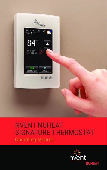
SECTION 4: THERMOSTATS4.1THERMOSTATSnVent NUHEAT SignatureWi-fi – Enabled Floor Heating Thermostat WiFi-enabled 3.5 in Color touchscreen Energy usage monitor 7-day programmability Dual-voltage (120 V & 240 V)nVent NUHEAT HomeUniversal Floor Heating Thermostat 3.5 in Color touchscreen Energy usage monitor 7-day programmability Dual-voltage (120 V & 240 V)nVent NUHEAT ElementNon-programmable Thermostat Manual temperature control Dual-voltage (120 V & 240 V)22 nVent.com/NUHEAT
SECTION 4: WARRANTY4.2WARRANTY INFORMATIONWARRANTY INFORMATIONnVent NUHEAT offers a 25-Year Product Warranty and/or 25-Year Total Care Warranty*when installed by a nVent NUHEAT Certified PRO Installer.The online warranty registration form must be completed at nVent.com/NUHEATwithin thirty (30) days from the date of installation and kept by the homeowner, togetherwith a copy of the commissioning report, relevant invoice, and photographs, showingthe product(s) in their entirety after installation but before the installation of theflooring material.* Total Care Warranty is an upgrade of our standard product warranty and additionally covers repairor replacement of the Product and restoring the floor in its original state or, if not possible, to anequivalent standard, at no cost to the Buyer. In order to remedy the defect, nVent must haveaccess to 1 m² (10 ft²) of the floor covering material.For more information, please call: 1.800.778.WARM(9276)or email: res.customercare@nVent.com.nVent.com/NUHEAT 23
appliances. Cable should not be installed closer than 6 in from the center of toilet drains, or under the footing of the toilet. 4. Indicate the thermostat location on the Installation Layout Plan. The thermostat . indicates the mechanical joint location and the start of the heating cable. 5. Draw the Cable Guides on the Installation Layout Plan.