Transcription
LWSDielectric LeafWetness SensorRevision: 11/18Copyright 2008 – 2018Campbell Scientific, Inc.
Limited Warranty“Products manufactured by CSI are warranted by CSI to be free from defects inmaterials and workmanship under normal use and service for twelve monthsfrom the date of shipment unless otherwise specified in the correspondingproduct manual. (Product manuals are available for review online atwww.campbellsci.com.) Products not manufactured by CSI, but that are resoldby CSI, are warranted only to the limits extended by the original manufacturer.Batteries, fine-wire thermocouples, desiccant, and other consumables have nowarranty. CSI’s obligation under this warranty is limited to repairing orreplacing (at CSI’s option) defective Products, which shall be the sole andexclusive remedy under this warranty. The Customer assumes all costs ofremoving, reinstalling, and shipping defective Products to CSI. CSI will returnsuch Products by surface carrier prepaid within the continental United States ofAmerica. To all other locations, CSI will return such Products best way CIP(port of entry) per Incoterms 2010. This warranty shall not apply to anyProducts which have been subjected to modification, misuse, neglect, improperservice, accidents of nature, or shipping damage. This warranty is in lieu of allother warranties, expressed or implied. The warranty for installation servicesperformed by CSI such as programming to customer specifications, electricalconnections to Products manufactured by CSI, and Product specific training, ispart of CSI's product warranty. CSI EXPRESSLY DISCLAIMS ANDEXCLUDES ANY IMPLIED WARRANTIES OF MERCHANTABILITYOR FITNESS FOR A PARTICULAR PURPOSE. CSI hereby disclaims,to the fullest extent allowed by applicable law, any and all warranties andconditions with respect to the Products, whether express, implied orstatutory, other than those expressly provided herein.”
AssistanceProducts may not be returned without prior authorization. The followingcontact information is for US and international customers residing in countriesserved by Campbell Scientific, Inc. directly. Affiliate companies handle repairsfor customers within their territories. Please visit www.campbellsci.com todetermine which Campbell Scientific company serves your country.To obtain a Returned Materials Authorization (RMA) number, contactCAMPBELL SCIENTIFIC, INC., phone (435) 227-9000. Please write theissued RMA number clearly on the outside of the shipping container. CampbellScientific’s shipping address is:CAMPBELL SCIENTIFIC, INC.RMA#815 West 1800 NorthLogan, Utah 84321-1784For all returns, the customer must fill out a “Statement of Product Cleanlinessand Decontamination” form and comply with the requirements specified in it.The form is available from our website at www.campbellsci.com/repair. Acompleted form must be either emailed to repair@campbellsci.com or faxed to(435) 227-9106. Campbell Scientific is unable to process any returns until wereceive this form. If the form is not received within three days of productreceipt or is incomplete, the product will be returned to the customer at thecustomer’s expense. Campbell Scientific reserves the right to refuse service onproducts that were exposed to contaminants that may cause health or safetyconcerns for our employees.
SafetyDANGER — MANY HAZARDS ARE ASSOCIATED WITH INSTALLING, USING, MAINTAINING, AND WORKING ON OR AROUNDTRIPODS, TOWERS, AND ANY ATTACHMENTS TO TRIPODS AND TOWERS SUCH AS SENSORS, CROSSARMS, ENCLOSURES,ANTENNAS, ETC. FAILURE TO PROPERLY AND COMPLETELY ASSEMBLE, INSTALL, OPERATE, USE, AND MAINTAIN TRIPODS,TOWERS, AND ATTACHMENTS, AND FAILURE TO HEED WARNINGS, INCREASES THE RISK OF DEATH, ACCIDENT, SERIOUSINJURY, PROPERTY DAMAGE, AND PRODUCT FAILURE. TAKE ALL REASONABLE PRECAUTIONS TO AVOID THESE HAZARDS.CHECK WITH YOUR ORGANIZATION'S SAFETY COORDINATOR (OR POLICY) FOR PROCEDURES AND REQUIRED PROTECTIVEEQUIPMENT PRIOR TO PERFORMING ANY WORK.Use tripods, towers, and attachments to tripods and towers only for purposes for which they are designed. Do not exceed design limits.Be familiar and comply with all instructions provided in product manuals. Manuals are available at www.campbellsci.com or bytelephoning (435) 227-9000 (USA). You are responsible for conformance with governing codes and regulations, including safetyregulations, and the integrity and location of structures or land to which towers, tripods, and any attachments are attached. Installationsites should be evaluated and approved by a qualified engineer. If questions or concerns arise regarding installation, use, ormaintenance of tripods, towers, attachments, or electrical connections, consult with a licensed and qualified engineer or electrician.General Prior to performing site or installation work, obtain required approvals and permits. Complywith all governing structure-height regulations, such as those of the FAA in the USA. Use only qualified personnel for installation, use, and maintenance of tripods and towers, andany attachments to tripods and towers. The use of licensed and qualified contractors is highlyrecommended. Read all applicable instructions carefully and understand procedures thoroughly beforebeginning work. Wear a hardhat and eye protection, and take other appropriate safety precautions whileworking on or around tripods and towers. Do not climb tripods or towers at any time, and prohibit climbing by other persons. Takereasonable precautions to secure tripod and tower sites from trespassers. Use only manufacturer recommended parts, materials, and tools.Utility and Electrical You can be killed or sustain serious bodily injury if the tripod, tower, or attachments you areinstalling, constructing, using, or maintaining, or a tool, stake, or anchor, come in contact withoverhead or underground utility lines. Maintain a distance of at least one-and-one-half times structure height, 20 feet, or the distancerequired by applicable law, whichever is greater, between overhead utility lines and thestructure (tripod, tower, attachments, or tools). Prior to performing site or installation work, inform all utility companies and have allunderground utilities marked. Comply with all electrical codes. Electrical equipment and related grounding devices should beinstalled by a licensed and qualified electrician.Elevated Work and Weather Exercise extreme caution when performing elevated work. Use appropriate equipment and safety practices. During installation and maintenance, keep tower and tripod sites clear of un-trained or nonessential personnel. Take precautions to prevent elevated tools and objects from dropping. Do not perform any work in inclement weather, including wind, rain, snow, lightning, etc.Maintenance Periodically (at least yearly) check for wear and damage, including corrosion, stress cracks,frayed cables, loose cable clamps, cable tightness, etc. and take necessary corrective actions. Periodically (at least yearly) check electrical ground connections.WHILE EVERY ATTEMPT IS MADE TO EMBODY THE HIGHEST DEGREE OF SAFETY IN ALL CAMPBELL SCIENTIFIC PRODUCTS,THE CUSTOMER ASSUMES ALL RISK FROM ANY INJURY RESULTING FROM IMPROPER INSTALLATION, USE, ORMAINTENANCE OF TRIPODS, TOWERS, OR ATTACHMENTS TO TRIPODS AND TOWERS SUCH AS SENSORS, CROSSARMS,ENCLOSURES, ANTENNAS, ETC.
Table of ContentsPDF viewers: These page numbers refer to the printed version of this document. Use thePDF reader bookmarks tab for links to specific sections.1. Introduction. 12. Precautions . 13. Initial Inspection . 14. QuickStart . 15. Overview . 35.15.2Measurement .3Leaf Mimicry .46. Specifications . 47. Installation . 57.17.27.3Field Installation.5Wiring .6Programming .67.3.1 Voltage Measurement .67.3.2 Minutes Dry, Minutes Wet or Contaminated, and Minutes Wet .77.3.3 Interpreting Data .78. Maintenance . 89. Acknowledgement . 8AppendicesA. Importing Short Cut Code Into CRBasic Editor . A-1B. Example Programs . B-1B.1B.2Example CR1000X Program.B-1Example CR6 Program .B-27-1.7-2.7-3.LWS Dielectric Leaf Wetness Sensor .5Top view of a typical LWS installation.5Typical LWS response .7Figuresi
Table of ContentsTablesB-1.B-2.CR1000X Example Program Wiring .B-1CR6 Example Program Wiring .B-2CRBasic ExamplesB-1.B-2.CR1000X Program for Measuring the LWS .B-1CR6 Program for Measuring the LWS .B-2ii
LWS Dielectric Leaf Wetness Sensor1.IntroductionDirect measurement of leaf wetness is problematic. Secure long-termattachment of a sensor to a representative living leaf is difficult. Leaf position,sun exposure, and health are in constant flux. To avoid these problems, leafwetness sensors have been developed to estimate by inference the wetness ofnearby leaves. The LWS estimates leaf surface wetness by measuring thedielectric constant of the sensor upper surface. The LWS is able to detect thepresence of miniscule amounts of water or ice. Individual sensor calibration isnot normally necessary.NOTE2.3.4.This manual provides information only for CRBasic data loggers.For retired Edlog data logger support, see an older manual atwww.campbellsci.com/old-manuals.Precautions READ AND UNDERSTAND the Safety section at the front of thismanual. Care should be taken when opening the shipping package to not damage orcut the cable jacket. If damage to the cable is suspected, contact CampbellScientific. Although the LWS is rugged, it should be handled as a precision scientificinstrument. Over time, the accumulation of dust and bird droppings can cause the dryoutput to rise. We recommend that the sensor be periodically cleanedusing a moist cloth, or when you detect elevated dry output. The LWS is intended only for applications wherein the data loggerprovides short excitation, leaving the sensor quiescent most of the time.Continuous excitation may cause the sensor to exceed governmentspecified limits on electromagnetic emissions.Initial Inspection Upon receipt of the LWS, inspect the packaging and contents for damage.File damage claims with the shipping company. The model number and cable length are printed on a label at theconnection end of the cable. Check this information against the shippingdocuments to ensure the correct product and cable length are received.QuickStartA video that describes data logger programming using Short Cut is available etting-started-programpart-3. Short Cut is an easy way to program your data logger to measure theLWS and assign data logger wiring terminals. Short Cut is available as a1
LWS Dielectric Leaf Wetness Sensordownload on www.campbellsci.com. It is included in installations ofLoggerNet, PC200W, PC400, or RTDAQ.The following procedure also describes programming with Short Cut.1.Open Short Cut and click Create New Program.2.Double-click the data logger model.3.In the Available Sensors and Devices box, type LWS. You can alsolocate the sensor in Sensors Miscellaneous Sensors folder. Double-clickLWS Dielectric Leaf Wetness Sensor. Enter the Dry threshold (mV) and Wet threshold (mV) values (see Section 7.3.3, Interpreting Data(p. 7), for information about determining the dry threshold and wet thresholdvalues).4.Click on the Wiring tab to see how the sensor is to be wired to the datalogger. Click OK after wiring the sensor.5.Repeat steps three and four for other sensors. Click Next.2
LWS Dielectric Leaf Wetness SensorNOTE5.6.In Output Setup, type the scan rate, meaningful table names, and theData Output Storage Interval.7.Select the output options.8.Click Finish and save the program. Send the program to the data logger ifthe data logger is connected to the computer.9.If the sensor is connected to the data logger, check the output of the sensorin LoggerNet, PC400, RTDAQ, or PC200W to make sure it is makingreasonable measurements.Short Cut uses the execution interval to make the minutes wet, dry,and contaminated calculations (Section 7.3.2, Minutes Dry,Minutes Wet or Contaminated, and Minutes Wet (p. 7)). You needto take this into account while editing the Short Cut program.Overview5.1MeasurementThe LWS measures the dielectric constant of a zone approximately 1 cm fromthe upper surface of the sensor. The dielectric constant of water ( 80) and ice3
LWS Dielectric Leaf Wetness Sensor( 5) are much higher than that of air ( 1), so the measured dielectric constantis strongly dependent on the presence of moisture or frost on the sensorsurfaces. The sensor outputs a millivolt signal proportional to the dielectric ofthe measurement zone, and therefore proportional to the amount of water or iceon the sensor surface.5.2Leaf MimicryThe LWS is designed to approximate the thermodynamic properties of mostleaves. If the specific heat of a typical leaf is estimated at 3750 J kg–1 K–1,density estimated at 0.95 g/cm3, and thickness estimated at 0.4 mm, then theheat capacity of the leaf is 1425 J m–2 K–1. This heat capacity is closelyapproximated by the thin (0.65 mm) fiberglass construction of the LWS, whichhas a heat capacity of 1480 J m–2 K–1. By mimicking the thermodynamicproperties of a leaf, the LWS closely matches the wetness state of the canopy.The sensor closely matches the radiative properties of real leaves. Healthyleaves generally absorb solar radiation in much of the visible portion of thespectrum, but selectively reject much of the energy in the near-infrared. Thesurface coating of the LWS absorbs well in the near-infrared region, but thewhite color reflects most of the visible radiation. Spectroradiometermeasurements indicate that the overall radiation balance of the sensor closelymatches that of a healthy leaf. During normal use, prolonged exposure tosunlight can cause some yellowing of the coating, which does not affect thefunction of the sensor. The surface coating is hydrophobic — similar to a leafwith a hydrophobic cuticle. The sensor matches the wetness state of these typesof leaves, but may not match the wetness duration of pubescent leaves orleaves with less waxy cuticles.6.SpecificationsFeatures: Imitates characteristics of a leaf Does not require painting or calibration of individual sensors Detects trace amounts of water or ice on the leaf surface Compatible with Campbell Scientific CRBasic data loggers:CR200(X) series, CR300 series, CR6 series, CR800 series, CR1000,CR1000X, CR3000, CR5000, and CR9000(X)Settling Time:10 msExcitation:2.5 Vdc (2 mA) to 5.0 Vdc (7 mA)Minimum Excitation Time:10 msOutput:300 to 1250 mV (depends on excitationvoltage)Operating Temperature:–40 to 60 CLength:12.0 cm (4.7 in)Width:5.8 cm (2.3 in)4
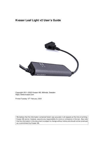
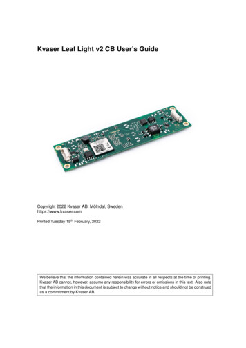
LWS Dielectric Leaf Wetness Sensor7.Height:0.8 cm (0.3 in)Maximum Cable Length:75 m (246 ft)Interchangeability:Interchangeable without painting or individualcalibrationInstallationIf you are programming your data logger with Short Cut, skip Section 7.2,Wiring (p. 6), and Section 7.3, Programming (p. 6). Short Cut does this work foryou. See Section 4, QuickStart (p. 1), for a Short Cut tutorial.7.1Field InstallationThe LWS includes two holes for mounting the sensor on a small diameter rodby using zip ties or 4-40 bolts (FIGURE 7-1 and FIGURE 7-2). Typicaldeployment is in a plant canopy or on a weather station mast.FIGURE 7-1. LWS Dielectric Leaf Wetness SensorFIGURE 7-2. Top view of a typical LWS installation5
LWS Dielectric Leaf Wetness Sensor7.2WiringTABLE 7-1. Wire Color, Wire Function, and Data Logger ConnectionWireColorWire FunctionData Logger Connection TerminalBrown orWhiteVoltageexcitation inputU configured for voltage excitation1, EX,VX (voltage excitation)Orange orRedAnalog voltageoutputU configured for single-ended analoginput1, SE (single-ended, analog input)ClearShield (analog ground)1U7.3terminals are automatically configured by the measurement instruction.ProgrammingShort Cut is the best source for up-to-date data logger programming code.If your data acquisition requirements are simple, you can probably create andmaintain a data logger program exclusively with Short Cut. If your dataacquisition needs are more complex, the files that Short Cut creates are a greatsource for programming code to start a new program or add to an existingcustom program.NOTEShort Cut cannot edit programs after they are imported and editedin CRBasic Editor.A Short Cut tutorial is available in Section 4, QuickStart (p. 1). If you wish toimport Short Cut code into CRBasic Editor to create or add to a customizedprogram, follow the procedure in Appendix Appendix A, Importing Short CutCode Into CRBasic Editor (p. A-1). Programming basics for CRBasic dataloggers are provided in the following sections. Complete program examples forCRBasic data loggers can be found in Appendix B, Example Programs (p. B-1).Programming basics and programming examples for Edlog data loggers areprovided at www.campbellsci.com/old-manuals.7.3.1 Voltage MeasurementThe LWS requires excitation voltage between 2.5 and 5 Vdc. It produces anoutput voltage dependent on the dielectric constant of the medium surroundingthe sensor. Output voltage ranges from 10 to 50% of the excitation voltage.Except for the CR200(X), CRBasic data loggers use the BRHalf() instructionto measure the sensor output. The BRHalf() instruction and parameters are sPEx,ExmV,RevEx,Settling,fN1/Integ,Mult,Offset)The CR200(X) uses the ExDelSE() CRBasic instruction to measure the sensoroutput. The ExDelSE() instruction and parameters are as follows:ExDelSE( Dest, Reps, SEChan, ExChan, ExmV, Delay, Mult, Offset )6
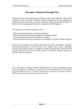
LWS Dielectric Leaf Wetness Sensor7.3.2 Minutes Dry, Minutes Wet or Contaminated, and Minutes WetThe Voltage measurement can be further categorized into Minutes Dry,Minutes Wet or Contaminated, and Minutes Wet as follows:If mV 274 ThenMinutes Dry Scan Interval in seconds / 60ElseIf mV 284 ThenMinutes Wet Scan Interval in seconds / 60ElseMinutes Wet or Contaminated Scan Interval in seconds / 60End IfEnd IfGiven a 2500 mV excitation, the thresholds of less than 274 mV for dry andgreater or equal to 284 mV for wet are recommended by Meter Environment.However, the thresholds can be adjusted as needed. Minutes dry, minutes wetor contaminated, and minutes wet can then be totaled and stored for any givenperiod (table interval). Minutes wet or contaminated can be considered a wetcondition or a contaminated condition depending on the user’s evaluation ofthe sensors condition. The user may also choose to store an average of thevoltage measurement for post processing later.7.3.3 Interpreting DataMany leaf wetness applications, such as phytopathology, require a Booleaninterpretation of leaf wetness data. A Boolean threshold is determined byanalyzing a few days of time-series data. The time-series data in FIGURE 7-3,was obtained using a 5 Vdc excitation. The sensor yields approximately445 mV when dry, approximately 475 mV when frosted, and greater than475 mV when wet. Therefore, a Boolean wetness threshold of 500 mV shouldserve well for interpreting these data.FIGURE 7-3. Typical LWS response7
LWS Dielectric Leaf Wetness SensorDuration of leaf wetness can be determined either by post processing of data,or by programming the data logger to accumulate time of wetness based on theBoolean threshold. Accumulation of dust and debris, such as avian fecalmatter, will change the Boolean threshold. So, while having the data loggeraccumulate time of leaf wetness, or time of frost, may be convenient, assuranceof data quality requires retention of the base millivolt measurements.NOTE8.Collect data frequently enough to capture changes in surfacewetness. A sample frequency of 15 minutes or less is usuallynecessary to accurately capture leaf wetness duration.MaintenanceThe accumulation of dust and debris will cause the dry output to increase andchange the Boolean threshold. Clean the sensing surface with a moist clothperiodically or when elevated dry output is detected.The LWS leaf wetness sensor withstands typical outdoor radiation andprecipitation loads for more than two years. If using the LWS in areas withunusually high radiation loads, Campbell Scientific recommends applyingRevivex UV Protectant (available from www.gearaid.com/products/revivexcare-uv-protect) every 45 days. Revivex UV Protectant is the only tested andapproved UV blocking system for this leaf wetness sensor. Revivex UVProtectant was formerly known as Gear Aid UV Tech.To apply Revivex UV Protectant:9.1.Wipe sensor clean.2.Spray sensor surface with Revivex UV Protectant.3.Rub with soft cloth until dry.AcknowledgementPortions of this manual are copyrighted by Meter Environment and are used bypermission.8
Appendix A. Importing Short Cut CodeInto CRBasic EditorThis tutorial shows: Importing a Short Cut program into a program editor for additionalrefinement Importing a wiring diagram from Short Cut into the comments of acustom programShort Cut creates files, which can be imported into CRBasic Editor. Assumingdefaults were used when Short Cut was installed, these files reside in theC:\campbellsci\SCWin folder: .DEF (wiring and memory usage information).CR2 (CR200(X)-series datalogger code).CR300 (CR300-series datalogger code).CR6 (CR6-series datalogger code).CR8 (CR800-series datalogger code).CR1 (CR1000 datalogger code).CR1X (CR1000X-series datalogger code).CR3 (CR3000 datalogger code).CR5 (CR5000 datalogger code)Import Short Cut code and wiring diagram into CRBasic Editor:1.NOTECreate the Short Cut program following the procedure in Section 4,QuickStart (p. 1). Finish the program. On the Advanced tab, click theCRBasic Editor button. The program opens in CRBasic with the namenoname.CR . Provide a name and save the program.Once the file is edited with CRBasic Editor, Short Cut can nolonger be used to edit the program it created.2.The program can now be edited, saved, and sent to the data logger.3.Import wiring information to the program by opening the associated .DEFfile. By default, it is saved in the c:\campbellsci\SCWin folder. Copy andpaste the section beginning with heading “–Wiring for CRXXX–” into theCRBasic program, usually at the head of the file. After pasting, edit theinformation such that an apostrophe (') begins each line. This characterinstructs the data logger compiler to ignore the line when compiling. Youcan highlight several lines of CRBasic code then right-click and selectComment Block. (This feature is demonstrated at about 5:10 in theCRBasic Features video.)A-1
Appendix B. Example ProgramsFor these programs, the dry threshold is 274 and the wet threshold is 284. Todetermine minutes dry, minutes wet or contaminated, and minutes wet, thevalue 0.8333333 is used. This value was calculated based on a 5 s scan interval(scan interval/60 s). Refer to Section 7.3.2, Minutes Dry, Minutes Wet orContaminated, and Minutes Wet (p. 7), for more information.B.1 Example CR1000X ProgramThe wiring for the example is shown in TABLE B-1.TABLE B-1. CR1000X Example Program WiringColorFunctionCR1000XBrown or WhiteExcitationVX1Orange or RedAnalog OutSE1ClearAnalog Ground CRBasic Example B-1. CR1000X Program for Measuring the LWS'CR1000X'Declare Variables and UnitsPublic BattVPublic PTemp CPublic LWmVPublic LWMDryPublic LWMConPublic LWMWetUnitsUnitsUnitsUnitsUnitsUnitsBattV VoltsPTemp C Deg CLWmV mVLWMDry MinutesLWMCon MinutesLWMWet Minutes'Define Data in,10)Sample(1,BattV,FP2)Sample(1,PTemp ndTable'Main ProgramBeginProg'Main ScanB-1
Appendix B. Example ProgramsScan(5,Sec,1,0)'Default Data Logger Battery Voltage measurement 'BattV'Battery(BattV)'Default Wiring Panel Temperature measurement 'PTemp C'PanelTemp(PTemp C,60)'LWS Dielectric Leaf Wetness Sensor measurement 0,60,2500,0)'Determine Minutes Dry 'LWMDry', Minutes Wet or Contaminated 'LWMCon','and Minutes Wet 'LWMWet'. The value 0.08333333 is the scan rate divided by'60 s (5 s/60 s 0.08333333).LWMDry 0LWMCon 0LWMWet 0If LWmV 274 ThenLWMDry 0.08333333ElseIf LWmV 284 ThenLWMWet 0.08333333ElseLWMCon 0.08333333EndIfEndIf'Call Data Tables and Store ogB.2 Example CR6 ProgramThe wiring for the example is shown in TABLE B-2.TABLE B-2. CR6 Example Program WiringColorFunctionCR6Brown or WhiteExcitationU1Orange or RedAnalog OutU2ClearAnalog Ground CRBasic Example B-2. CR6 Program for Measuring the LWS'CR6 Series'Declare Variables and UnitsPublic BattVPublic PTemp CPublic LWmVPublic LWMDryPublic LWMConPublic LWMWetUnitsUnitsUnitsUnitsUnitsUnitsBattV VoltsPTemp C Deg CLWmV mVLWMDry MinutesLWMCon MinutesLWMWet MinutesB-2
Appendix B. Example Programs'Define Data ndTable'Main ProgramBeginProg'Main ScanScan(5,Sec,1,0)'Default Data Logger Battery Voltage measurement 'BattV'Battery(BattV)'Default Wiring Panel Temperature measurement 'PTemp C'PanelTemp(PTemp C,60)'LWS Dielectric Leaf Wetness Sensor measurement 0,60,2500,0)'Determine Minutes Dry 'LWMDry', Minutes Wet or Contaminated 'LWMCon','and Minutes Wet 'LWMWet'. The value 0.08333333 is the scan rate divided by'60 s (5 s/60 s 0.08333333).LWMDry 0LWMCon 0LWMWet 0If LWmV 274 ThenLWMDry 0.08333333ElseIf LWmV 284 ThenLWMWet 0.08333333ElseLWMCon 0.08333333EndIfEndIf'Call Data Tables and Store DataCallTable HourlyCallTable DailyNextScanEndProgB-3
Campbell Scientific Worldwide OfficesAustraliaLocation: Garbutt, QLD AustraliaEmail: info@campbellsci.com.auWebsite: www.campbellsci.com.auBrazilLocation: São Paulo, SP BrazilEmail: andread@campbellsci.com.brWebsite: www.campbellsci.com.brCanadaLocation: Edmonton, AB CanadaEmail: dataloggers@campbellsci.caWebsite: www.campbellsci.caChinaLocation: Beijing, P. R. ChinaEmail: info@campbellsci.com.cnWebsite: www.campbellsci.com.cnCosta RicaLocation: San José, Costa RicaEmail: info@campbellsci.ccWebsite: www.campbellsci.ccFranceLocation: Antony, FranceEmail: info@campbellsci.frWebsite: www.campbellsci.frGermanyLocation: Bremen, GermanyEmail: info@campbellsci.deWebsite: www.campbellsci.deSouth AfricaLocation: Stellenbosch, South AfricaEmail: sales@csafrica.co.zaWebsite: www.campbellscientific.co.zaSoutheast AsiaLocation: Bangkok, ThailandEmail: info@campbellsci.asiaWebsite: www.campbellsci.asiaSpainLocation: Barcelona, SpainEmail: info@campbellsci.esWebsite: www.campbellsci.esUKLocation: Shepshed, Loughborough, UKEmail: sales@campbellsci.co.ukWebsite: www.campbellsci.co.ukUSALocation: Logan, UT USAEmail: info@campbellsci.comWebsite: www.campbellsci.comPlease visit www.campbellsci.com/contact to obtain contact informationfor your local US or international representative.
The LWS measures the dielectric constant of a zone approximately 1 cm from the upper surface of the sensor. The dielectric constant of water ( 80) and ice . NOTE . LWS Dielectric Leaf Wetness Sensor . 4 ( 5) are much higher than that of air ( 1), so the measured dielectric constant ,