Transcription
Aerial Cable Installation PracticesInstall 06 (previously MP – 1009 Issue 2)Issue #3August 2016
AERIAL CABLE INSTALLATION PRACTICESCONTENTS1.2.3.4.5.6.7.PAGEGeneral . 2Introduction . 3Precautions . 3Pre-survey . 5Materials and Equipment . 5Placing Cable Using The Moving Reel Method . 7Placing Cable Using The Stationary Reel Method . 8LIST OF ILLUSTRATIONS AND TABLESFigure 1 - Moving Reel Method of Cable Placement . 3Figure 2 - Stationary Reel Method of Cable Placement. 3Figure 3 - Cable Block . 6Figure 4 - Strand Storage . 6Figure 5 - Splice Van Location . 7Figure 6 - Lashing Wire Clamp . 7Figure 7 - Setup for Moving Reel Method. 8Figure 8 - Setup for Stationary Reel Method . 9Figure 9 - Snatch Block . 10Figure 10 - Pull-back Lashing of Cable . 101.0 GENERAL1.01 This procedure provides general information for the installation of aerial fiberoptic cables. The methods described are intended for guideline use only, as it isimpossible to cover all the various conditions that may arise during aninstallation. Individual company practices for placing aerial fiber optic cableshould supersede any conflicting instructions in this document when they do notexceed the cable’s optical and mechanical performance specifications.1.02 Placement methods for aerial fiber optic cable are very similar to those of strandsupported copper cable. However it must be kept in mind that fiber optic cable isa high capacity transmission medium which can have its transmissioncharacteristics degraded when subjected to excessive pulling force, sharp bends,and crushing forces. These losses may not be revealed until long after installationis complete. For these reasons extra care must be taken during the entireinstallation procedure.1.03 It is assumed that the personnel using the information presented in this documenthave prior experience in the planning, engineering or placement of aerial cable.Page 2 of 12
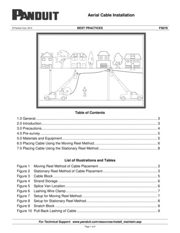
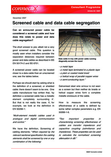
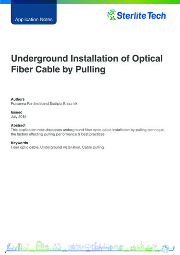
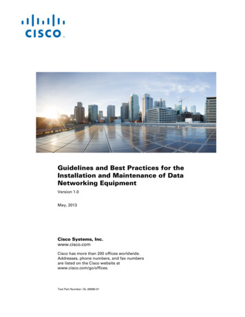
2.0 INTRODUCTION2.01 Two basic methods of lashing fiber optic cable are presented in this document:Figure 1. - The Moving Reel Method of Cable Placement1. The moving reel method is used when reel-carrying vehicles can drive themajority of the cable route. Using this method, the fiber optic cable is raisedand lashed to the strand in one operation.Figure 2. - The Stationary Reel Method of Cable Placement2. The stationary method is used when reel-carrying vehicles cannot drive themajority of the cable route. Using this method, the fiber optic cable is pulledinto place beneath the strand using cable blocks. Lashing the cable to thestrand then begins at the far end of the cable route with the lasher being pulledtoward the stationary reel location at the near end.3.0 PRECAUTIONS3.01 The following are some suggested precautions that should be observed whenworking with fiber optic cables. Before starting any aerial fiber optic cableinstallation, all personnel must be thoroughly familiar with Occupational Safetyand Hazard Act (OSHA) regulations. Also, company safety precautions for aerialfiber optic cable operations should be reviewed before work begins and practicedduring the entire installation process.3.02 Before cable installation begins, the cable reels should be carefully inspected forany imperfections such as nails, broken flanges, cable crossovers, or any thatmight cause damage to the cable as it is payed out. Precautions should be taken toprotect stored reels from possible damage by vandals or other sources when leftunattended. The thermal protective covering provided on each reel of fiber opticcable should always remain in place when storing reels.Page 3 of 12
3.03 Whenever cable from the reel is placed on the pavement or other surfaces, itshould be protected with barricades or cones to prevent possible vehicular orpedestrian traffic damage. A “figure-eight” configuration should be used when thecable is removed from the reel and piled on the ground. This prevents kinking andtwisting of the cable which could cause damage. Fiber optic cable should not becoiled in a continuous direction except for lengths of 100 ft (30 meters) or less.The minimum size for the “figure-eight” is about 15 ft (4.5 meters) in length witheach loop 5 ft (1.5 meters) to 8 ft (2.4 meters) in diameter.Note: Figure 8 machines should not be used without approval from Prysmian.Many machines violate the cable bend radius which can flatten buffer tubes.They are also problematic with central tube designs which contain radial strengthmembers.3.04 Standard Prysmian fiber optic cable has a maximum recommended pullingtension of 600 lbs. The maximum pulling tension is not to be exceeded. Pleaseconsult Prysmian’s Methods and Procedures for the proper installation and use ofpulling grips. Prysmian cables may be ordered from the factory with pulling eyesalready installed.3.05 Fiber optic cables are more susceptible to performance degradation due to tightbending than are copper cables. The minimum bend radius of each cable isproportional to the cable’s diameter. A general guideline is that a cable undertension should not be exposed to a bend radius less than 20 times thecable diameter and a cable with no tension should not be exposed to abend radius less than 10 times the cable diameter.3.06 Never during the pull-in or lashing process should the cable experience sags,bends or twists, that produce a bend in the cable whose radius meets or exceedsthat specified as the minimum bend radius for the cable being installed. Failure toobserve proper cable handling procedures during cable placement can voidPrysmian’s cable warranty and may result in permanent damage to thetransmission characteristics of the cable. A reduction in the cable’s transmissioncharacteristics introduced during installation may not reveal itself until long afterthe installation process has been completed.Page 4 of 12
4.0 PRE-SURVEY4.01 A pre-survey of the fiber cable route is very important in planning for an aerialoptical fiber cable project. The purpose of a pre-survey is to determine if anywork may be required along the proposed route before cable placement begins.Each section of the route must be properly prepared before cable installationbegins.4.02 One of the objectives of the pre-survey is to determine where each reel of fiberoptic cable is to be placed. Slack locations and cable storage requirements mustalso be considered along with splice locations. The pre-survey will verifyconstruction methods, special tools required, or possibly require a revision ofpreliminary splice locations.4.03 The characteristics of the ground along the route need to be investigated. Trees orother obstructions, which could hinder placing operation, should be noted.Clearance issues over roadways, driveways, etc. need to be taken into accountbefore cable placement begins. Consult the National Electric Safety Code (NESC)if uncertain of clearance requirements.4.04 The method of cable placement and the tools necessary for placement aredependent upon vehicle accessibility to the cable route. In areas where a vehiclecannot go, the cable will need to be pulled in. In other areas with easy vehicleaccessibility the cable can be lashed as it is taken off the vehicle’s reel.4.05 A good pre-survey will reveal clearance and separation issues on joint-use polesbefore they delay construction. It will also qualify the condition and size of theexisting poles to be used, the condition and size of the existing pole’s anchors andreveal the need for any new poles before placement operations begins.5.0 MATERIALS AND EQUIPMENT5.01 When an aerial lift truck is required for lashing operations, personnel in the aeriallift truck bucket will be responsible for directing all operations required in placingthe lift into working position, using the lift, and restoring it to travel position. Theoperator of the truck will operate the truck only at the direction of the person inthe lift bucket. There must be good communications between the person in thebucket and the driver of the truck.5.02 A reel carrier or a cable trailer is required for transport and paying out of the cableas it is lashed to the strand.5.03 A pulling eye or grip is used to provide a connection point between the cable andthe pulling line. The pulling eye can be factory installed by Prysmian. A pullinggrip can be field installed provided Prysmian Methods and Procedures arefollowed.Page 5 of 12
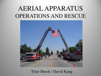
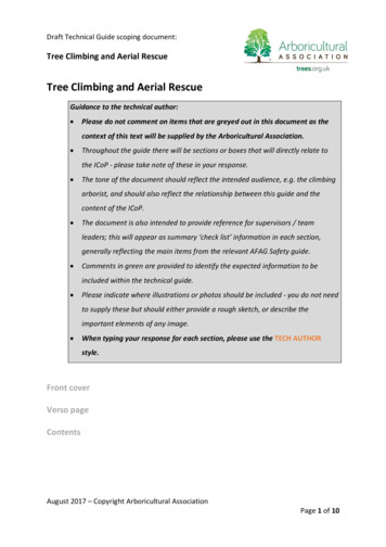
5.04 Cable blocks and snatch blocks will be required for placing cable when theMoving Reel Method is not practical (See Figure 9 for an illustration of a SnatchBlock).Figure 3 - Cable Block5.05 All slack cable storage locations require the installation of slack cable storagebrackets. The slack cable storage bracket ensures a proper bending radius for thestored fiber optic cable and provides for horizontal storage and tiering for storageof multiple cables and loops.Figure 4 - Strand Storage5.06 The Outside Plant Engineer responsible for the project determines strandrequirements.5.07 Lashing fiber optic cable to copper cable, either twisted pair or coaxial, increasesthe stress placed upon the fiber optic cable because of the difference in expansioncoefficient, extra weight on the strand, and damage from work being conductedon adjacent cables. These factors can contribute to an accelerated failure of thefiber optic cable.5.08 The lasher used to secure the fiber optic cable to the strand must be of the correctsize to lash the cable without damaging the cable. If the lasher is undersized, itwill put periodic dents in the cable as it passes along its length. When doublelashing is required, wire must be loaded into both sides of the lasher. It isrecommended that the operator of the lasher read and be familiar with themanufacturer’s instructions for the lashing machine that they are using.Page 6 of 12
6.0 PLACING CABLE USING THE MOVING REEL METHOD6.01 The moving reel method is used in locations where a cable reel trailer or aerial lifttruck can be moved along the pole line and there are no obstructions between thereel and the suspension strand.6.02 The moving reel method of cable placement has an advantage over the stationaryreel method in that temporary cable blocks and pull-in lines are not necessary.Whenever possible, the moving reel method should be used.6.03 When it is practical, the movement of the reel should be in the same direction asany nearby traffic.6.04 Cable suspension clamps are to be tightened at least one span ahead of the cablelashing operation to prevent tension build-up in the strand as lashing progresses.6.05 Start the cable lashing operation by removing enough cable from the reel to reachPrysmianfrom strand level to a splicing vehicle below plus 16 feet or so of extra slack.Figure 5 - Splice Van Location6.06 Lift the cable guide and lasher to the strand. Using a lift or a hand line, raise thecable up to the strand and pass it through the cable guide, positioning the cable inthe lasher. The lashing wire should be placed around the tension rollers and thenterminated in the lashing wire clamp.Figure 6 - Lashing Wire ClampPage 7 of 12
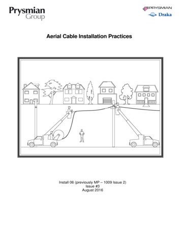
6.07 Attach separate pulling lines from the vehicle to the lasher and the cable guidePrysmian.Figure 7 - Setup for Moving Reel Method6.08 As the reel movement begins, secure the cable at the pole to prevent anymovement along the strand until the lasher has moved 50 feet down the strand.6.09 The cable reel must allow smooth cable pay-out to allow the cable to smoothlyenter the cable guide at stand level. Hand pull cable from the reel to ensure atension-free feed into the cable guide preceding the lasher.6.10 The reel-carrying vehicle should maintain an approximate 50-foot lead distanceahead of the lasher, and drive as close to the pole line as possible.6.11 If it becomes necessary to stop the lasher mid-span, a proper tension and bendradius of the cable must be maintained at the lasher.6.12 Upon reaching a pole:1. Clamp the lashing wire to the strand.2. Transfer the guide, lasher, etc., to the other side of the pole.6.13 Continue the cable installation, span-by-span from the starting point towards theend of the cable until the entire cable run is completely lashed and properlysagged.7.0 PLACING CABLE USING THE STATIONARY REEL METHOD7.01 Unlike the moving reel method in which the cable placement and lashingoperations take place at the same time, the stationary reel method requires twoseparate operations. First: the cable is pulled into place beneath the strand supported by cableblocks (See Figure 8). Second: the cable is then lashed to the strand beginning at the cable end andending at the stationary reel location (See Figure 10).Page 8 of 12
PrysmianFigure 8 - Setup for Stationary Reel Method7.02 Cable reel trailers should be disconnected from their towing vehicles. The reelshould be leveled and the trailer wheel securely chocked.7.03 A cable guide should be installed to guide the cable from the reel to its positionbeneath the strand. It is important that the guide or sheave be greater than thespecified minimum cable bend radius. It is i
fiber optic cable operations should be reviewed before work begins and practiced during the entire installation process. 3.02 Before cable installation begins, the cable reels should be carefully inspected for any imperfections such as nails, broken flanges, cable crossovers, or any that might cause damage to the cable as it is payed out. Precautions should be taken toFile Size: 215KBPage Count: 12