Transcription
P1/PX1Original Series METAL PumpsEngineeringOperation &MaintenanceSimplify your processLISTED79WIL-10300-E-12REPLACES WIL-10300-E-11
TA B L E O F C O N T E N T SSECTION 1 CAUTIONS—READ FIRST! . . . . . . . . . . . . . . . . . . . . . . . . . . . . . . . . . . . . . . . . . . . . . .1SECTION 2 WILDEN PUMP DESIGNATION SYSTEM . . . . . . . . . . . . . . . . . . . . . . . . . . . . . . . . .2SECTION 3 HOW IT WORKS—PUMP & AIR DISTRIBUTION SYSTEM. . . . . . . . . . . . . . . .3SECTION 4 DIMENSIONAL DRAWINGS . . . . . . . . . . . . . . . . . . . . . . . . . . . . . . . . . . . . . . . . . . . . .4SECTION 5 PERFORMANCEA. P1 Performance CurvesRubber-Fitted . . . . . . . . . . . . . . . . . . . . . . . . . . . . . . . . . . . . . . . . . . . . . . . . . . . . . . . .6TPE-Fitted . . . . . . . . . . . . . . . . . . . . . . . . . . . . . . . . . . . . . . . . . . . . . . . . . . . . . . . . . . .6PTFE-Fitted . . . . . . . . . . . . . . . . . . . . . . . . . . . . . . . . . . . . . . . . . . . . . . . . . . . . . . . . . .7B. PX1 PerformanceOperating Principal . . . . . . . . . . . . . . . . . . . . . . . . . . . . . . . . . . . . . . . . . . . . . . . . . . 10How to Use this EMS Curve . . . . . . . . . . . . . . . . . . . . . . . . . . . . . . . . . . . . . . . . . . . 11Performance CurvesRubber-Fitted . . . . . . . . . . . . . . . . . . . . . . . . . . . . . . . . . . . . . . . . . . . . . . . . . . . . 14TPE-Fitted . . . . . . . . . . . . . . . . . . . . . . . . . . . . . . . . . . . . . . . . . . . . . . . . . . . . . . .15PTFE-Fitted . . . . . . . . . . . . . . . . . . . . . . . . . . . . . . . . . . . . . . . . . . . . . . . . . . . . . .16C. Suction Lift Curves . . . . . . . . . . . . . . . . . . . . . . . . . . . . . . . . . . . . . . . . . . . . . . . . . . . . 19SECTION 6 SUGGESTED INSTALLATION, OPERATION & TROUBLESHOOTING . . . . . . .20SECTION 7 ASSEMBLY / DISASSEMBLY . . . . . . . . . . . . . . . . . . . . . . . . . . . . . . . . . . . . . . . . . . .23Grounding Strap for CSA Pumps . . . . . . . . . . . . . . . . . . . . . . . . . . . . . . . . . . . . . . . . . . .25SECTION 8 EXPLODED VIEW & PARTS LISTINGP1 Rubber/TPE-Fitted . . . . . . . . . . . . . . . . . . . . . . . . . . . . . . . . . . . . . . . . . . . . . . . . . . . . .30P1 PTFE-Fitted . . . . . . . . . . . . . . . . . . . . . . . . . . . . . . . . . . . . . . . . . . . . . . . . . . . . . . . . . . .32PX1 Rubber-Fitted . . . . . . . . . . . . . . . . . . . . . . . . . . . . . . . . . . . . . . . . . . . . . . . . . . . . . . . .34PX1 PTFE-Fitted . . . . . . . . . . . . . . . . . . . . . . . . . . . . . . . . . . . . . . . . . . . . . . . . . . . . . . . . .36ClassSECTION 9 ELASTOMER OPTIONS . . . . . . . . . . . . . . . . . . . . . . . . . . . . . . . . . . . . . . . . . . . . . . . . .38I&II OzoneNNOSEsDep Uleting SubtancesActAir f 1990anCle ents o.S.U ndmeAm
Section 1CAUTIONS—READ FIRST!CAUTION: Do not apply compressed air to the exhaust port— pump will not function.CAUTION: The process fluid and cleaning fluids must bechemically compatible with all wetted pump components.Consult Chemical Resistance Guide (E4).CAUTION: Do not over-lubricate air supply — excesslubrication will reduce pump performance. Pump is pre-lubed.CAUTION: Do not exceed 82 C (180 F) air inlet temperaturefor Pro-Flo X models.CAUTION: Do not under any circumstance loosen the setscrew located at the adjuster dial of the Pro-Flo X pump. Ifthe set screw is loose when the pump is pressurized, it couldeject and cause injury to anyone in the area.CAUTION: Pumps should be thoroughly flushed beforeinstalling into process lines. FDA and USDA approved pumpsshould be cleaned and/or sanitized before being used.CAUTION: Always wear safety glasses when operatingpump. If diaphragm rupture occurs, material being pumped maybe forced out air exhaust.TEMPERATURE LIMITS:Neoprene–17.7 C to 93.3 C0 F to 200 FBuna-N–12.2 C to 82.2 C10 F to 180 FEPDM–51.1 C to 137.8 C –60 F to 280 FViton –40 C to 176.7 C –40 F to 350 FSaniflex –28.9 C to 104.4 C –20 F to 220 FPolytetrafluoroethylene (PTFE)4.4 C to 104.4 C40 F to 220 FPolyurethane –12.2 C to 65.6 C10 F to 150 FTetra-Flex PTFE w/Neoprene Backed4.4 C to 107.2 C40 F to 225 FTetra-Flex PTFE w/EPDM Backed-10 C to 137 C14 F to 280 FCAUTION: Before any maintenance or repair is attempted,the compressed air line to the pump should be disconnectedand all air pressure allowed to bleed from pump. Disconnectall intake, discharge and air lines. Drain the pump by turningit upside down and allowing any fluid to fl ow into a suitablecontainer.CAUTION: Blow out air line for 10 to 20 seconds beforeattaching to pump to make sure all pipeline debris is clear. Usean in-line air filter. A 5µ (micron) air filter is recommended.NOTE: When installing PTFE diaphragms, it is importantto tighten outer pistons simultaneously (turning in oppositedirections) to ensure tight fi t. (See torque specifications inSection 7.)NOTE: Not all materials are available for all models. Refer toSection 2 for material options for your pump.NOTE: Canadian Standards Association (CSA) configuredpumps should not be used in temperatures lower than 0.0ºC to51.6ºC (32ºF to 125ºF).NOTE: Cast Iron PTFE-fi tted pumps come standard from thefactory with expanded PTFE gaskets installed in the diaphragmbead of the liquid chamber. PTFE gaskets cannot be re-used.Consult PS-TG for installation instructions during reassembly.NOTE: UL listed configured pumps have the followingtemperature limits:UL 79 Buna-12.2 C (10 F) to 52 C (125 F)NOTE: Before starting disassembly, mark a line from eachliquid chamber to its corresponding air chamber. This line willassist in proper alignment during reassembly.CAUTION: When choosing pump materials, be sure to checkthe temperature limits for all wetted components. Example:Viton has a maximum limit of 176.7 C (350 F) but polypropylenehas a maximum limit of only 79 C (175 F).CAUTION: Pro-Flo pumps cannot be used in submersibleapplications. Pro-Flo X is available in both submersible andnon-submersible options. Do not use non-submersible Pro-FloX models in submersible applications. Turbo-Flo pumps canalso be used in submersible applications.CAUTION: Maximum temperature limits are based uponmechanical stress only. Certain chemicals will significantlyreduce maximum safe operating temperatures. ConsultChemical Resistance Guide (E4) for chemical compatibility andtemperature limits.CAUTION: Tighten all hardware prior to installation.CAUTION: The gas outlet of CSA configured pumps must bevented to a safe location in accordance with local codes or, inthe absence of local codes, an industry or nationally recognizedcode having jurisdiction over the specified installation.WARNING: Prevention of static sparking — If static sparkingoccurs, fire or explosion could result. Pump, valves, andcontainers must be grounded to a proper grounding point whenhandling flammable fluids and whenever discharge of staticelectricity is a hazard.CAUTION: For U.L. listed pumps, all pipe connections are to bemade using U.L. classified gasoline-resistant pipe compound.CAUTION: Canadian Standards Association (CSA) configuredpumps must be electrically grounded using the groundinglocation identified. Improper grounding can cause improperand dangerous operation.CAUTION: For U.L. listed pumps all installations must conformto NFPA 30, NFPA 30A, and all other applicable codes.CAUTION: For U.L. listed pumps, air exhaust port is to beconnected to pipe or tubing to be routed outdoors or otherlocation determined to be equivalent.CAUTION: Do not exceed 8.6 bar (125 psig) air supplypressure.CAUTION: For U.L. listed pumps, pump is to be groundedusing the jam-nut located at the top of the long vertical carriagebolt. The ground connection is marked with a tag having thegrounding symbol.CAUTION: Canadian Standards Association (CSA) configuredpumps should not exceed 6.9 bar (100 psig) sweet gas supplypressure.CAUTION: For U.L. listed pumps, do not exceed 3.4 bar (50psig) air supply pressure.Grounding SymbolWIL-10300-E-121WILDEN PUMP & ENGINEERING, LLC
Section 2W IL DEN PUMP DESIGN AT ION SYS T EMP1/PX1 ORIGINAL METALLEGEND13 mm (½") PumpMaximum Flow Rate:62.8 lpm (16.6 gpm)xPX1 / X X X X X / XXX / XX / X XX / XXXXMODELATEXO-RINGSVALVE SEATVALVE BALLSDIAPHRAGMSAIR VALVECENTER SECTIONWETTED PARTS & OUTER PISTONSPECIALTYCODE(if applicable)MATERIAL CODESMODEL P1 Pro-FloPX1 Pro-Flo X XPX1 ATEX Pro-Flo XTMAIR VALVEA ALUMINUM (PX1 only)G CONDUCTIVE ACETAL (P1only)J CONDUCTIVEPOLYPROPYLENE (P1 only)WETTED PARTS & OUTER PISTONAA ALUMINUM / ALUMINUM L ACETAL (P1 only)AZ ALUMINUM / NO PISTON P POLYPROPYLENE (P1 only)SS STAINLESS STEEL /DIAPHRAGMSSTAINLESS STEELSZ STAINLESS STEEL /XBS CONDUCTIVE BUNA-NNO PISTON(Two Red Dots)BNS BUNA-N (Red Dot)CENTER SECTIONFSS SANIFLEX [Hytrel (Cream)]AA ALUMINUM (PX1 only)PUS POLYURETHANE (Clear)GG CONDUCTIVE ACETALTEU PTFE w/EPDM(P1 only)BACK-UP (White)JJ CONDUCTIVEPOLYPROPYLENE (P1 only) THU PTFE W/HIGH-TEMPBUNA-N BACK-UP (White)LL ACETAL (P1 only)PP POLYPROPYLENE (P1 only) TNU PTFE W/NEOPRENEBACK-UP (White)TNL PTFE W/NEOPRENEBACK-UP O-RING,IPD (White) VTS VITON (White Dot) WFS WIL-FLEX [Santoprene(Orange Dot)]EPS EPDM (Blue Dot)VALVE BALLBN BUNA-N (Red Dot)FS SANIFLEX [Hytrel (Cream)]PU POLYURETHANE (Brown)TF PTFE (White) VT VITON (White Dot) WF WIL-FLEX [Santoprene(Orange Dot)]EP EPDM (Blue Dot)VALVE SEATA ALUMINUMS STAINLESS STEEL V VITON (White Dot)VALVE SEAT O-RINGBN BUNA-NFS SANIFLEX [Hytrel (Cream)]PU POLYURETHANE (Brown)TF PTFE (White) WF WIL-FLEX [Santoprene ]EP EPDMSPECIALTY CODES00230067007000790080010001020103Wing nutsSaniflo FDA, Wil-Gard II 220VSaniflo FDATri-clamp fittings, wing nutsTri-clamp fittings ONLYWil-Gard II 110VWil-Gard II sensor wires ONLYWil-Gard II 220V0120 Saniflo FDA, Wil-Gard II 110V0206 PFA coated hardware, Wil-Gard II sensor wires ONLY0390 CSA Approved0495 U.L. Approved0502 PFA coated hardware0603 PFA coated hardware, Wil Gard 110V0608 PFA coated hardware, Wil Gard 220VNOTE: The Wilden UL 79 Listed products covered by this manual are PX1 models followed by AA or SS, followed by AA, followed by A, followed byBNS, followed by BN, followed by A or S, followed by BN, followed by 0495. Wilden UL Listed pumps have been evaluated for use at a25 C (77F) ambient temperature with a maximum inlet pressure of 3.4 Bar (50 PSI).WILDEN PUMP & ENGINEERING, LLC2WIL-10300-E-12
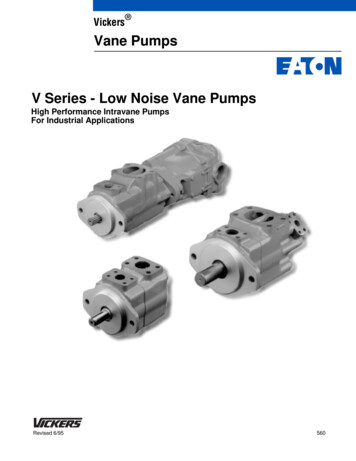
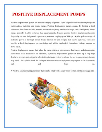
Section 3HOW IT WORKSThe Wilden diaphragm pump is an air-operated, positive displacement, self-priming pump. These drawings show the flow patternthrough the pump upon its initial stroke. It is assumed the pump has no fluid in it prior to its initial stroke.BABABAOPENFIGURE 1 The air valve directs pressurized air tothe back side of diaphragm A. The compressed airis applied directly to the liquid column separated byelastomeric diaphragms. The diaphragm acts as aseparation membrane between the compressed airand liquid, balancing the load and removing mechanical stress from the diaphragm. The compressed airmoves the diaphragm away from the center block ofthe pump. The opposite diaphragm is pulled in bythe shaft connected to the pressurized diaphragm.Diaphragm B is on its suction stroke; air behind thediaphragm has been forced out to the atmospherethrough the exhaust port of the pump. The movement of diaphragm B toward the center block of thepump creates a vacuum within chamber B. Atmospheric pressure forces fluid into the inlet manifoldforcing the inlet valve ball off its seat. Liquid is freeto move past the inlet valve ball and fill the liquidchamber (see shaded area).FIGURE 2 When the pressurized diaphragm,diaphragm A, reaches the limit of its dischargestroke, the air valve redirects pressurized air to theback side of diaphragm B. The pressurized air forcesdiaphragm B away from the center block while pulling diaphragm A to the center block. Diaphragm Bis now on its discharge stroke. Diaphragm B forcesthe inlet valve ball onto its seat due to the hydraulicforces developed in the liquid chamber and manifold of the pump. These same hydraulic forceslift the discharge valve ball off its seat, while theopposite discharge valve ball is forced onto its seat,forcing fluid to flow through the pump discharge.The movement of diaphragm A toward the centerblock of the pump creates a vacuum within liquidchamber A. Atmospheric pressure forces fluid intothe inlet manifold of the pump. The inlet valve ball isforced off its seat allowing the fluid being pumpedto fill the liquid chamber.FIGURE 3 At completion of the stroke, the air valveagain redirects air to the back side of diaphragm A,which starts diaphragm B on its exhaust stroke. Asthe pump reaches its original starting point, eachdiaphragm has gone through one exhaust and onedischarge stroke. This constitutes one completepumping cycle. The pump may take several cyclesto completely prime depending on the conditions ofthe application.HOW IT WORKS—AIR DISTRIBUTION SYSTEMThe Pro-Flo patented air distribution system incorporates twomoving parts: the air valve spool and the pilot spool. The heart ofthe system is the air valve spool and air valve. This valve designincorporates an unbalanced spool. The smaller end of the spoolis pressurized continuously, while the large end is alternatelypressurized then exhausted to move the spool. The spool directspressurized air to one air chamber while exhausting the other.The air causes the main shaft/diaphragm assembly to shift toone side — discharging liquid on that side and pulling liquid inon the other side. When the shaft reaches the end of its stroke,the inner piston actuates the pilot spool, which pressurizes andexhausts the large end of the air valve spool. The repositioningof the air valve spool routes the air to the other air chamber.WIL-10300-E-123WILDEN PUMP & ENGINEERING, LLC
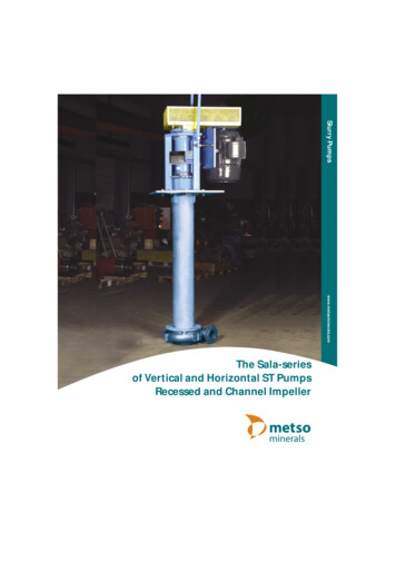
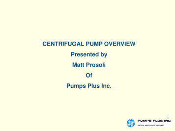
Section 4DIMENSIONAL DR AWINGSP1 M E TALDIMENSIONSITEMMET
NOTE: The Wilden UL 79 Listed products covered by this manual are PX1 models followed by AA or SS, followed by AA, followed by A, followed by BNS, followed by BN, followed by A or S, followed by BN, followed by 0495. Wilden UL Listed pumps have been evaluated for use at a 25 C (77F) ambient temperature with a maximum inlet pressure of 3.4 Bar (50 PSI). WILDEN PUMP & ENGINEERING,