Transcription
EOMEngineeringOperation &MaintenanceP2Original SeriesMetal PumpW h e r eI n n o v a t i o nF l o w swww.wildenpump.comWIL-10181-E-05REPLACES WIL-10181-E-04
TA B L E O F C O N T E N T SSECTION 1 CAUTIONS—READ FIRST! . . . . . . . . . . . . . . . . . . . . . . . . . . . . . . . . . . . . . . . . . . . . . .1SECTION 2 WILDEN PUMP DESIGNATION SYSTEM. . . . . . . . . . . . . . . . . . . . . . . . . . . . . . . . .2SECTION 3 HOW IT WORKS—PUMP & AIR DISTRIBUTION SYSTEM . . . . . . . . . . . . . . . .3SECTION 4 DIMENSIONAL DRAWINGS . . . . . . . . . . . . . . . . . . . . . . . . . . . . . . . . . . . . . . . . . . . . .4SECTION 5 PERFORMANCEA. P2 Performance CurvesRubber-Fitted. . . . . . . . . . . . . . . . . . . . . . . . . . . . . . . . . . . . . . . . . . . . . . . . . . . . . . . .TPE-Fitted. . . . . . . . . . . . . . . . . . . . . . . . . . . . . . . . . . . . . . . . . . . . . . . . . . . . . . . . . . .Reduced-Stroke PTFE-Fitted. . . . . . . . . . . . . . . . . . . . . . . . . . . . . . . . . . . . . . . . . . . .Full-Stroke PTFE-Fitted . . . . . . . . . . . . . . . . . . . . . . . . . . . . . . . . . . . . . . . . . . . . . . . .B. Suction-Lift Curves . . . . . . . . . . . . . . . . . . . . . . . . . . . . . . . . . . . . . . . . . . . . . . . . . . . . .55667SECTION 6 SUGGESTED INSTALLATION, OPERATION & TROUBLESHOOTING. . . . . . . .8SECTION 7 ASSEMBLY / DISASSEMBLY . . . . . . . . . . . . . . . . . . . . . . . . . . . . . . . . . . . . . . . . . . .11Air Valve/Center Section Assembly. . . . . . . . . . . . . . . . . . . . . . . . . . . . . . . . . . . . . . . . . . 13Reassembly Hints & Tips. . . . . . . . . . . . . . . . . . . . . . . . . . . . . . . . . . . . . . . . . . . . . . . . . . 15SECTION 8 EXPLODED VIEW & PARTS LISTINGP2 Metal. . . . . . . . . . . . . . . . . . . . . . . . . . . . . . . . . . . . . . . . . . . . . . . . . . . . . . . . . . . . . . . 16P2 Metal Saniflo 1935/2004/EC. . . . . . . . . . . . . . . . . . . . . . . . . . . . . . . . . . . . . . . . . . . . 18SECTION 9 ELASTOMER OPTIONS. . . . . . . . . . . . . . . . . . . . . . . . . . . . . . . . . . . . . . . . . . . . . . . . .I&II OzoneClassNNOSEbsDep Uleting SutancesAct 90Airan s of 19letCnU.S. ndmeeAm20
Section 1CAUTIONS—READ FIRST! CAUTION: Do not apply compressed air to the exhaust port —pump will not function. WARNING: Prevention of static sparking — If static sparkingoccurs, fire or explosion could result. Pump, valves, andcontainers must be grounded to a proper grounding point whenhandling flammable fluids and whenever discharge of staticelectricity is a hazard. CAUTION: Do not over-lubricate air supply — excesslubrication will reduce pump performance. Pump is pre-lubed. TEMPERATURE LIMITS:Polypropylene0 C to 79 CPVDF–12 C to 107 CPFA7 C to 107 CNeoprene–18 C to 93 CBuna-N–12 C to 82 CEPDM–51 C to 138 CViton FKM–40 C to 177 CWil-Flex –40 C to 107 CSaniflex –29 C to 104 CPolyurethane–12 C to 66 CPolytetrafluoroethylene (PTFE)1 4 C to 104 CNylon–18 C to 93 CAcetal–29 C to 82 CSIPD PTFE with Neoprene-backed 4 C to 104 CSIPD PTFE with EPDM-backed –10 C to 137 CPolyethylene0 C to 70 CGeolast –40 C to 82 C1 CAUTION: Do not exceed 8.6 bar (125 psig) air supply pressure.32 F to 175 F10 F to 225 F20 F to 225 F0 F to 200 F10 F to 180 F–60 F to 280 F–40 F to 350 F–40 F to 225 F–20 F to 220 F10 F to 150 F40 F to 220 F0 F to 200 F–20 F to 180 F40 F to 220 F14 F to 280 F32 F to 158 F–40 F to 180 F CAUTION: The process fluid and cleaning fluids must bechemically compatible with all wetted pump components.Consult Chemical Resistance Guide (E4). CAUTION: Pumps should be thoroughly flushed beforeinstalling into process lines. FDA- and USDA approved pumpsshould be cleaned and/or sanitized before being used. CAUTION: Always wear safety glasses when operatingpump. If diaphragm rupture occurs, material being pumped maybe forced out air exhaust. CAUTION: Before any maintenance or repair is attempted,the compressed air line to the pump should be disconnectedand all air pressure allowed to bleed from pump. Disconnectall intake, discharge and air lines. Drain the pump by turningit upside down and allowing any fluid to flow into a suitablecontainer. CAUTION: Blow out air line for 10 to 20 seconds beforeattaching to pump to make sure all pipeline debris is clear. Usean in-line air filter. A 5μ (micron) air filter is recommended.4 C to 149 C (40 F to 300 F) - 13 mm (1/2") and 25 mm (1") models only.NOTE: Not all materials are available for all models. Refer toSection 2 for material options for your pump. NOTE: When installing PTFE diaphragms, it is importantto tighten outer pistons simultaneously (turning in oppositedirections) to ensure tight fit. (See torque specifications inSection 7.) CAUTION: When choosing pump materials, be sure to checkthe temperature limits for all wetted components. Example:Viton has a maximum limit of 178 C (350 F), but polypropylenehas a maximum limit of only 79 C (175 F). NOTE: Before starting disassembly, mark a line from eachliquid chamber to its corresponding air chamber. This line willassist in proper alignment during reassembly. CAUTION: Maximum temperature limits are based uponmechanical stress only. Certain chemicals will significantlyreduce maximum safe operating temperatures. ConsultChemical Resistance Guide (E4) for chemical compatibility andtemperature limits.WIL-10181-E-05 CAUTION: Tighten all hardware prior to installation.1WILDEN PUMP & ENGINEERING, LLC
Section 2W IL DEN PUMP DESIGN AT ION SYS T EMP2 METALLEGEND25 mm (1") PumpMaximum Flow Rate:172 lpm (45.5 gpm)PX / X X X X X / XXX / XX / X XX / 2XXXSEATO-RINGSMODELVALVE SEATSVALVE BALLSDIAPHRAGMSAIR VALVECENTER SECTIONWETTED PARTS & OUTER PISTONSPECIALTYCODE(if applicable)MATERIAL CODESMODELP2 25 mm (1")DIAPHRAGMSBNS BUNA-N (Red Dot)EPS EPDM (blue dot)WETTED PARTS & OUTER PISTON FBS SANITARY BUNA1,3(Two Yellow Dots)AA ALUMINUM / ALUMINUMFES SANITARY EPDM 1,3AZ ALUMINUM / NO PISTON(Two Blue Dots)SS STAINLESS STEEL /FSS SANIFLEX (Cream)STAINLESS STEELFWL SANITARY WIL-FLEX SZ STAINLESS STEEL / NOIPD1,3PISTONFWS SANITARY WIL-FLEX 1,3LEL PTFE – EPDM LAMINATECENTER SECTIONIPD1,2,3PP POLYPROPYLENENES NEOPRENE (Green Dot)LL ACETALPUS POLYURETHANE (Clear)TEU PTFE w/EPDMAIR VALVEBACK-UP (White)1,2,3P POLYPROPYLENETNU PTFE w/NEOPRENEL ACETALBACK-UP (White)TSS FULL-STROKE PTFEw/SANIFLEXTM BACK-UP 1,2,3TSU PTFE W/SANIFLEX BACK-UP (White)1,2,3TWS FULL-STROKE PTFEw/WIL-FLEXTM BACK-UP1,2,3 VTS VITON (Silver or WhiteDot)WFS WIL-FLEX (Orange Dot)VALVE BALLSBN BUNA-N (Red Dot)EP EPDM (Blue Dot)FS SANIFLEX (Cream)1,3NE NEOPRENE (Green Dot)PU POLYURETHANE (Clear)TF PTFE1,2,3 VT VITON (Silver or White Dot)WF WIL-FLEX (Orange Dot)VALVE SEATSA ALUMINUMS STAINLESS STEELVALVE SEAT O-RINGBN BUNA-N (Red Dot)EP EPDMFS SANIFLEX [HYLREL (Cream)1,3NE NEOPRENEPU POLYURETHANE (Clear)TF PTFE (White)1,2,3WF WIL-FLEX 1NOTE:1 Meets Requirements of FDA CFR21.1772 Meets Requirements of USP Class VI3 Meets Requirements of 1935/2004/ECSPECIALTY PT threadedBSPT threadedWing NutsSaniflo FDATri-clamp fittings, wing nutsTri-clamp fittings onlyWil-Gard 110VWil-Gard sensor wires ONLYWil-Gard 220VPump Cycle Monitor (sensor & wires)Pump Cycle Monitor (module, sensor & wires)2070E Saniflo FDA (1935/2004/EC)NOTE: Most elastomers use colored dots for identification. Not all models are available with all material options.WILDEN PUMP & ENGINEERING, LLC2WIL-10181-E-05
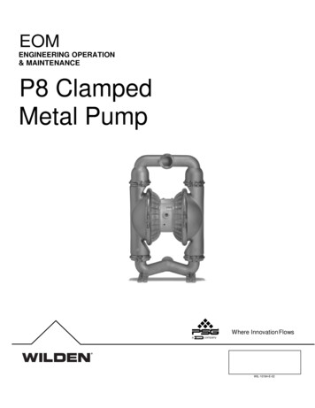
Section 3Section 3HOW IT WORKS—PUMPThe Wilden diaphragm pumpis anIair-operated,HOWT W O RpositiveK S displacement, self-priming pump. These drawings show flow patternthrough the pump upon its initial stroke. It is assumed the pump has no fluid in it prior to its initial stroke.The Wilden diaphragm pump is an air-operated, positive displacement, self-priming pump. These drawings show the flow patternthrough the pump upon its initial stroke. It is assumed the pump has no fluid in it prior to its initial stroke.BABABAOPENFIGURE 1 The air valve directs pressurizedair to the back side of diaphragm A. Thecompressed air is applied directly to theliquid column separated by elastomericdiaphragms. The diaphragm acts asa separation membrane between theFIGURE 1 The air valve directs pressurized aircompressed air and liquid, balancing theto the back side of diaphragm A. The compressedremovingmechanicalstressair is loadappliedanddirectlyto the liquidcolumn sepathe diaphragm.compressedrated fromby elastomericdiaphragms.TheThe diaphragmacts airas amovesseparationbetweenthe membranediaphragmawaythefromcompressed air and liquid, balancing the load andthe center of the pump. The oppositeremoving mechanical stress from the diaphragm.diaphragmairismovespulledin by theshaftThe compressedthe diaphragmawayto thepressurizedfrom connectedthe center blockof thepump. The diaphragm.oppositediaphragmis pulledBinisbyontheitsshaftconnectedto airDiaphragmsuctionstroke;the pressurized diaphragm. Diaphragm B is on itsbehind the diaphragm has been forcedsuction stroke; air behind the diaphragm has beenatmospheretheexhaustforcedoutout toto theatmosphere throughthrough theexhaustporttheThepump.The ofmovementport ofthe ofpump.movementdiaphragm ofB towardthe centerBblockof thethepumpcreatesofa thediaphragmtowardcentervacuum within chamber B. Atmospheric pressurepump creates a vacuum within chamber B.forces fluid into the inlet manifold forcing the inletforcesfluidvalve Atmosphericball off its seat. pressureLiquid is freeto movepastintothevalveinletballmanifoldforcingthe inletvalvethe inletand fill theliquid chamber(seeshadedarea).balloff its seat. Liquid is free to movepast the inlet valve ball and fill the liquidchamber (see shaded area).FIGURE 2 When the pressurized diaphragm,diaphragm A, reaches the limit of its dischargestroke, the air valve redirects pressurizedair to the back side of diaphragm B. Thepressurized air forces diaphragm B awayfrom the center while pulling diaphragm AFIGURE 2 When the pressurized diaphragm,to the center.DiaphragmB ison itsdiaphragmA, reachesthe limit ofits nowdischargedischargestroke.DiaphragmB forcesthestroke,the air valveredirectspressurizedair to thebacksidevalveof diaphragmB. Theitspressurizedair forcesinletball ontoseat dueto thediaphragmB awayfrom developedthe center blockpullhydraulicforcesin whilethe liquiding diaphragm A to the center block. Diaphragm Bchamberandmanifoldofthepump.Theseis now on its discharge stroke. Diaphragm B forceshydrauliclift tothethesameinlet valveball onto forcesits seat duethe dischargehydraulicforcesdevelopedtheseat,liquid whilechambermanivalveball offinitstheandoppositefolddischargeof the pump.samehydraulicforcesvalveTheseball isforcedonto itsseat,lift the discharge valve ball off its seat, while theforcingfluid valveto flowthepumpoppositedischargeball isthroughforced ontoits seat,discharge.movementof diaphragmforcingfluid to Theflow throughthe pumpdischarge. AThetowardmovementdiaphragmA towardcenter athe ofcenterof thepumpthecreatesblockof the pumpvacuum withinliquidvacuumwithincreatesliquida chamberA. Atmoschamber A. Atmospheric pressure forces fluid intophericpressureforcesfluidintothethe inlet manifold of the pump. The inlet valve ballinletismanifoldof thepump.ballforcedoff its seatallowingtheThefluid inletbeingvalvepumpedto fillthe liquidchamber.is forcedoffits seat allowing the fluid beingpumped to fill the liquid chamber.FIGURE 3 At completion of the stroke,the air valve again redirects air to theback side of diaphragm A, which startsdiaphragm B on its exhaust stroke. Asthe pump reaches its original startingpoint, each diaphragm has gone throughFIGURE 3 At completion of the stroke, the air valveone redirectsexhaustairandstroke.againto theonebackdischargeside of diaphragmA,This startsconstitutesonecompletewhichdiaphragmB onits exhaustpumpingstroke. epumpitsmaytakeseveralcyclesdiaphragmhas gonethroughone exhaust onand theoneto completelyprimedependingdischarge stroke. This constitutes one completeconditionsoftheapplication.pumping cycle. The pump may take several cyclesto completely prime depending on the conditions ofthe application.HOW IT WORKS—AIR DISTRIBUTION SYSTEMHOW IT WORKS—AIR DISTRIBUTION SYSTEMThe Pro-Flo patented air distribution system incorporates twomoving parts: the air valve spool and the pilot spool. The heart ofthe system is the air valve spool and air valve. This valve designincorporates an unbalanced spool. The smaller end of the spoolis pressurized continuously, while the large end is alternatelypressurized then exhausted to move the spool. The spool directspressurized air to one air chamber while exhausting the other.The air causes the main shaft/diaphragm assembly to shift toone side — discharging liquid on that side and pulling liquid inon the other side. When the shaft reaches the end of its stroke,the inner piston actuates the pilot spool, which pressurizes andexhausts the large end of the air valve spool. The repositioningof the air valve spool routes the air to the other air chamber.TT4845 EOM P4/PV4M 5/05WIL-10181-E-053WILDEN PUMP & ENGINEERING, LLC3WILDEN PUMP & ENGINEERING, LLC
Section 4DIMENSIONAL
WILDEN PUMP & ENGINEERING, LLC 2 WIL-10181-E-05. The Wilden diaphragm pump is an air-operated, positive displacement, self-priming pump. These drawings show the flow pattern through the pump upon its initial stroke. It is assumed the pump has no fluid in it prior to its initial stroke. FIGURE 1 The air valve FIGURE 2directs pressurized air to the diaphragmback side of diaphragm A. The .