Transcription
PX15Original Series METAL PumpsEngineeringOperation &MaintenanceSimplify your processWIL-10330-E-04REPLACES WIL-10330-E-03
TA BL E OF CON T EN T SSECTION 1 CAUTIONS—READ FIRST!. . . . . . . . . . . . . . . . . . . . . . . . . . . . . . . . . . . . . . . . . . . . . . . . . . .1SECTION 2 WILDEN PUMP DESIGNATION SYSTEM. . . . . . . . . . . . . . . . . . . . . . . . . . . . . . . . . . . .2SECTION 3 HOW IT WORKS—PUMP & AIR DISTRIBUTION SYSTEM . . . . . . . . . . . . . . . . . . 3SECTION 4 DIMENSIONAL DRAWINGS . . . . . . . . . . . . . . . . . . . . . . . . . . . . . . . . . . . . . . . . . . . . . . . . . . 4SECTION 5 PERFORMANCEA. PX15 PerformanceOperating Principal . . . . . . . . . . . . . . . . . . . . . . . . . . . . . . . . . . . . . . . . . . . . . . . . . . . 6How to Use this EMS Curve . . . . . . . . . . . . . . . . . . . . . . . . . . . . . . . . . . . . . . . . . . . . 7Performance CurvesRubber-Fitted . . . . . . . . . . . . . . . . . . . . . . . . . . . . . . . . . . . . . . . . . . . . . . . . . . . . . . . . . . 10TPE-Fitted . . . . . . . . . . . . . . . . . . . . . . . . . . . . . . . . . . . . . . . . . . . . . . . . . . . . . . . . . . . . . 11PTFE-Fitted . . . . . . . . . . . . . . . . . . . . . . . . . . . . . . . . . . . . . . . . . . . . . . . . . . . . . . . . . . . . 12Full Stroke PTFE-Fitted . . . . . . . . . . . . . . . . . . . . . . . . . . . . . . . . . . . . . . . . . . . . . . . . . . . 13Ultra-Flex -Fitted . . . . . . . . . . . . . . . . . . . . . . . . . . . . . . . . . . . . . . . . . . . . . . . . . . . . . . 14B. Suction Lift Curves . . . . . . . . . . . . . . . . . . . . . . . . . . . . . . . . . . . . . . . . . . . . . . . . . . . . . . . . . . . 15SECTION 6 SUGGESTED INSTALLATION, OPERATION & TROUBLESHOOTING . . . . . . . . 16SECTION 7 ASSEMBLY / DISASSEMBLY . . . . . . . . . . . . . . . . . . . . . . . . . . . . . . . . . . . . . . . . . . . . . . . . 19SECTION 8 EXPLODED VIEW & PARTS LISTINGPX15 MetalFull Stroke-Fitted . . . . . . . . . . . . . . . . . . . . . . . . . . . . . . . . . . . . . . . . . . . . . . . . . . . . . . . . . . 26Reduced Stroke-Fitted . . . . . . . . . . . . . . . . . . . . . . . . . . . . . . . . . . . . . . . . . . . . . . . . . . . . . 28Full Stroke-Fitted (Plastic Center Block Assembly) . . . . . . . . . . . . . . . . . . . . . . . . . . . . 30Reduced Stroke-Fitted (Plastic Center Block Assembly) . . . . . . . . . . . . . . . . . . . . . . . 32SECTION 9 ELASTOMER OPTIONS. . . . . . . . . . . . . . . . . . . . . . . . . . . . . . . . . . . . . . . . . . . . . . . . . . . . . . 34
Section 1CAUTIONS—READ FIRST!CAUTION: Do not apply compressed air to theexhaust port — pump will not function.CAUTION: Do not exceed 82 C (180 F) air inlettemperature for Pro-Flo X models.CAUTION: Do not over-lubricate air supply —excess lubrication will reduce pump performance.Pump is pre-lubed.CAUTION: Pumps should be thoroughly flushedbefore installing into process lines. FDA andUSDA approved pumps should be cleaned and/or sanitized before being used.TEMPERATURE LIMITS:Neoprene–17.7 C to 93.3 C0 F to 200 FBuna-N–12.2 C to 82.2 C10 F to 180 FEPDM–51.1 C to 137.8 C –60 F to 280 F–40 C to 176.7 C –40 F to 350 FViton Saniflex –28.9 C to 104.4 C –20 F to 220 FPolytetrafluoroethylene (PTFE)4.4 C to 104.4 C 40 F to 220 FPolyurethane –12.2 C to 65.6 C10 F to 150 FTetra-Flex PTFE w/Neoprene Backed4.4 C to 107.2 C 40 F to 225 FTetra-Flex PTFE w/Nordel Backed-10 C to 137 C14 F to 280 FWil-Flex –40.0 C to 107.2 C –40 F to 225 FCAUTION: Always wear safety glasses whenoperating pump. If diaphragm rupture occurs,material being pumped may be forced out airexhaust.CAUTION: Before any maintenance or repair isattempted, the compressed air line to the pumpshould be disconnected and all air pressureallowed to bleed from pump. Disconnect allintake, discharge and air lines. Drain the pumpby turning it upside down and allowing any fluidto flow into a suitable container.CAUTION: Blow out air line for 10 to 20 secondsbefore attaching to pump to make sure all pipelinedebris is clear. Use an in-line air filter. A 5µ (micron)air filter is recommended.NOTE: Not all materials are available for allmodels. Refer to Section 2 for material optionsfor your pump.NOTE: When installing PTFE diaphragms, it isimportant to tighten outer pistons simultaneously(turning in opposite directions) to ensure tight fit.(See torque specifications in Section 7.)CAUTION: When choosing pump materials, besure to check the temperature limits for all wettedcomponents. Example: Viton has a maximumlimit of 176.7 C (350 F) but polypropylene has amaximum limit of only 79 C (175 F).NOTE: Cast Iron PTFE-fitted pumps comestandard from the factory with expanded PTFEgaskets installed in the diaphragm bead of theliquid chamber. PTFE gaskets cannot be re-used.Consult PS-TG for installation instructions duringreassembly.CAUTION: Maximum temperature limits arebased upon mechanical stress only. Certainchemicals will significantly reduce maximumsafe operating temperatures. Consult ChemicalResistance Guide (E4) for chemical compatibilityand temperature limits.NOTE: Before starting disassembly, mark a linefrom each liquid chamber to its corresponding airchamber. This line will assist in proper alignmentduring reassembly.WARNING: Prevention of static sparking — Ifstatic sparking occurs, fire or explosion couldresult. Pump, valves, and containers must begrounded to a proper grounding point whenhandling flammable fluids and wheneverdischarge of static electricity is a hazard.CAUTION: Pro-Flo pumps cannot be used insubmersible applications. Pro-Flo X is availablein both submersible and non-submersible options.Do not use non-submersible Pro-Flo X modelsin submersible applications. Turbo-Flo pumpscan also be used in submersible applications.CAUTION: Do not exceed 8.6 bar (125 psig) airsupply pressure.CAUTION: The process fluid and cleaning fluidsmust be chemically compatible with all wettedpump components. Consult Chemical ResistanceGuide (E4).WIL-10330-E-04CAUTION: Tighten all hardware prior to installation.1WILDEN PUMP & ENGINEERING, LLC
Section 2W IL DEN PUMP DESIGN AT ION SYS T EMLEGENDPX15 METAL76 mm (3") PumpMaximum Flow Rate:918 lpm (243 gpm)PX15 / XXXXX / XXX / XX / XXX / XXXXO-RINGSVALVE SEATVALVE BALLSDIAPHRAGMSAIR VALVECENTER BLOCKAIR CHAMBERSWETTED PARTS & OUTER PISTONMODELSPECIALTYCODE(if applicable)MATERIAL CODESDIAPHRAGMSBNS BUNA-N (Red Dot)XBS CONDUCTIVE BUNA-N(Two Red Dots) 2EPS EPDM (Blue Dot) 2PUS POLYURETHANE (Clear)NES NEOPRENE (Green Dot)TEU PTFE w/EPDMBACK-UP (white) 2TNU PTFE w/NEOPRENEBACK-UP (White)FSS SANIFLEX [Hytrel (Cream)]VTS VITON (White Dot)WFS WIL-FLEX [Santoprene (Orange Dot)]TSU PTFE W/SANIFLEX BACK-UP (White)BNU BUNA-N, ULTRA-FLEX EPU EPDM, ULTRA-FLEX 2NEU NEOPRENE,ULTRA-FLEX VTU VITON , ULTRA-FLEX TSS FULL STROKE PTFEW/SANIFLEX BACK-UPTWS FULL STROKE PTFEW/WIL-FLEX BACK-UPMODELPX15 76 MM (3")XPX15 76 MM (3") ATEXWETTED PARTS/OUTERPISTON1AA ALUMINUM /ALUMINUMSS STAINLESS STEEL /STAINLESS STEELWW DUCTILE IRON /DUCTILE IRONAIR CHAMBERSA ALUMINUMS 316 STAINLESS STEELCENTER BLOCKA ALUMINUMS 316 STAINLESS STEELP POLYPROPYLENEAIR VALVEA ALUMINUMS 316 STAINLESS STEELP POLYPROPYLENEVALVE BALLBN BUNA-N (Red Dot)FS SANIFLEX [Hytrel (Cream)]EP EPDM (Blue Dot) 2NE NEOPRENE (Green Dot)PU POLYURETHANE (Brown)TF PTFE (White) 2VT VITON (Silver or White Dot)WF WIL-FLEX [Santoprene (Orange Dot)]VALVE SEATA ALUMINUMBN BUNA-N (Red Dot)EP EPDM (Blue Dot) 2FS SANIFLEX [Hytrel (Cream)]NE NEOPRENE (Green Dot)PU POLYURETHANE (Brown)VT VITON (Silver or WhiteDot)WF WIL-FLEX [Santoprene (Orange Dot)]M MILD STEELS STAINLESS STEELVALVE SEAT O-RINGTF PTFE (White) 2NOTE:1. PTFE-fitted models require stainless steel outer piston.2. Meets the requirements of ATEX.SPECIALTY nal SS fastenersStallion balls & seats onlySaniFlo FDATri-clamp fittings, wing nutsTri-clamp fittings, ONLYWil-Gard II 110VWil-Gard II sensor wires ONLYWil-Gard II 220V0118 Stallion balls & seats only, BSPT0120Saniflo FDA, Wil-Gard II 110V0319 Single-Point Exhaust center block, BSPT0320 Single-Point Exhaust center block0324 Single-Point Exhaust center block,Screen based0327 Single-Point Exhaust center block,Stallion externals, balls & seats0341 Single-Point Exhaust center block,SaniFlo FDANOTE: MOST ELASTOMERIC MATERIALS USE COLORED DOTS FOR IDENTIFICATION.NOTE: Not all models are available with all materials options.Viton is a registered trademark of DuPont Dow Elastomers.WILDEN PUMP & ENGINEERING, LLC2WIL-10330-E-04
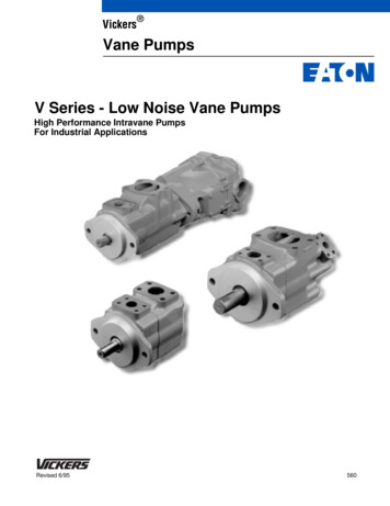
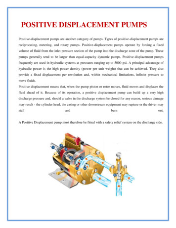
Section 3HOW IT WORKS—PUMPThe Wilden diaphragm pump is an air-operated, positive displacement, self-priming pump. These drawings show flow patternthrough the pump upon its initial stroke. It is assumed the pump has no fluid in it prior to its initial stroke.FIGURE 1 The air valve directs pressurizedair to the back side of diaphragm A. Thecompressed air is applied directly to theliquid column separated by elastomericdiaphragms. The diaphragm acts asa separation membrane between thecompressed air and liquid, balancing theload and removing mechanical stressfrom the diaphragm. The compressedair moves the diaphragm away fromthe center of the pump. The oppositediaphragm is pulled in by the shaftconnected to the pressurized diaphragm.Diaphragm B is on its suction stroke; airbehind the diaphragm has been forcedout to atmosphere through the exhaustport of the pump. The movement ofdiaphragm B toward the center of thepump creates a vacuum within chamber B.Atmospheric pressure forces fluid intothe inlet manifold forcing the inlet valveball off its seat. Liquid is free to movepast the inlet valve ball and fill the liquidchamber (see shaded area).FIGURE 2 When the pressurized diaphragm,diaphragm A, reaches the limit of its dischargestroke, the air valve redirects pressurizedair to the back side of diaphragm B. Thepressurized air forces diaphragm B awayfrom the center while pulling diaphragm Ato the center. Diaphragm B is now on itsdischarge stroke. Diaphragm B forces theinlet valve ball onto its seat due to thehydraulic forces developed in the liquidchamber and manifold of the pump. Thesesame hydraulic forces lift the dischargevalve ball off its seat, while the oppositedischarge valve ball is forced onto its seat,forcing fluid to flow through the pumpdischarge. The movement of diaphragm Atoward the center of the pump creates avacuum within liquid chamber A. Atmospheric pressure forces fluid into the inletmanifold of the pump. The inlet valve ballis forced off its seat allowing the fluid beingpumped to fill the liquid chamber.FIGURE 3 At completion of the stroke,the air valve again redirects air to theback side of diaphragm A, which startsdiaphragm B on its exhaust stroke. Asthe pump reaches its original startingpoint, each diaphragm has gone throughone exhaust and one discharge stroke.This constitutes one complete pumpingcycle. The pump may take several cyclesto completely prime depending on theconditions of the application.HOW IT WORKS—AIR DISTRIBUTION SYSTEMThe Pro-Flo patented air distribution system incorporates twomoving parts: the air valve spool and the pilot spool. The heart ofthe system is the air valve spool and air valve. This valve designincorporates an unbalanced spool. The smaller end of the spoolis pressurized continuously, while the large end is alternatelypressurized then exhausted to move the spool. The spool directspressurized air to one air chamber while exhausting the other.The air causes the main shaft/diaphragm assembly to shift toone side — discharging liquid on that side and pulling liquid inon the other side. When the shaft reaches the end of its stroke,the inner piston actuates the pilot spool, which pressurizes andexhausts the large end of the air valve spool. The repositioningof the air valve spool routes the air to the other air chamber.WIL-10330-E-043WILDEN PUMP & ENGINEERING, LLC
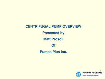
Section 4DIMENSIONAL DR AWINGSPX15 M e t a lDIMENSIONSITEMABCDEFGHJKLMNPRSTUVWXYZAAMETRIC 71693078430547815 DIA.STANDARD 4.312.110.111.10.72.82.712.13.312.018.8.6 DIA.PX15 M e t a l Sa n i f l o F DADIMENSIONSITEMABCDEFGHJKLMNPRSMETRIC (mm)52171396767810894064821642459935630525727915 DIA.STANDARD 12.010.111.0.6 DIA.WILDEN PUMP & ENGINEERING, LLC4WIL-10330-E-04
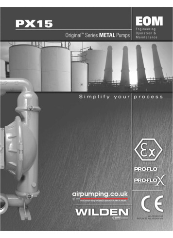
PX15METALPX15 PERFORMANCEWIL-10330-T-02
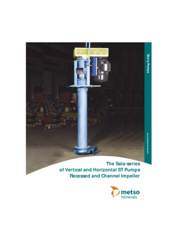
Section 5APro-Flo XTM Operating PrincipalThe Pro-Flo X air distribution system with thecontrol dial, the operator can select the optimalrevolutionary Efficiency Management System (EMS)balance of flow and efficiency that best meets theoffers flexibility never before seen in the world ofapplication needs. Pro-Flo X provides higherAODD pumps. Theperformance, lowerpatent-pending EMSoperationalis simple and easyand flexibility thatto use.exceedsWith theturn of an integratedcostspreviousindustry standards.AIR CONSUMPTION Turning the dialchanges therelationshipbetween air inletand exhaustporting.Each dial settingrepresents anentirely differentflow curveWILDEN PUMP & ENGINEERING, LLCPro-Flo X pumpsare shipped fromthe factory onsetting 4, whichis the highestflow rate settingpossible6Moving the dialfrom setting 4causes a decreasein flow and an evengreater decrease inair consumption. When the airconsumptiondecreases morethan the flowrate, efficiencyis improved andoperating costsare reduced.PX15 Performance
HOW TO USE THIS EMS CURVEExample 1EMS CURVESETTING 4 PERFORMANCE CURVEFigure 1Example data point 8.2Example data point GPMFigure 2flow multiplierair multipliercurve, draw vertical lines downward untilreaching the bottom scale on the chart. Thisidentifies the flow X Factor (in this case, 0.58)and air X Factor (in this case, 0.48).This is an e
WILDEN PUMP DESIGNATION SYSTEM. WIL-10330-E-04 3 WILDEN PUMP & ENGINEERING, LLC The Wilden diaphragm pump is an air-operated, positive displacement, self-priming pump. These drawings show fl ow pattern through the pump upon its initial stroke. It is assumed the pump has no fl uid in it prior to its initial stroke. FIGURE 1 The air valve directs pressurized air to the back side of