Transcription
CENTRIFUGAL PUMP OVERVIEWPresented byMatt ProsoliOfPumps Plus Inc.1
Centrifugal Pump- Definition Centrifugal Pump can be defined as a mechanical device usedto transfer liquid of various types. As the name suggests, it relies on the principal of Centrifugalforce. It converts the energy provided by a prime mover, such as anelectric motor, steam turbine, or gasoline engine, to energywithin the liquid being pumped.2
Types of PistonRotaryVaneGearScrewBlow CaseCentrifugalRegenerativeTurbineSpecial Effect3
Types of Pumps Continued . Positive Displacement Pump:– Operate by forcing a fixed volume of fluid from the inlet pressuresection of the pump into the discharge zone of the pump. They addenergy directly to a movable boundary, which imparts the energy tothe fluid. Kinetic Pumps:– Add energy directly through a rotating part in the form of velocity,and converts the velocity to pressure. Centrifugal Pumps Regenerative Pumps: Unique pump where the impeller is theonly moving part. It is used when high head and low flows arerequired. Special Effects Pumps: Miscellaneous pumps.4
Types of Pumps Continued .Centrifugal PumpImpeller betweenBearingsOverhung ImpellerClose CoupledSingle and TwoStageSeparatelyCoupled Singleand Two StageSeparatelyCoupled SingleStageTurbine TypeSeparatelyCoupledMultistageEnd SuctionInlineAxial Split Case(Horizontal)Axial Split Case(Horizontal)InlineFrame MountedRadial Split Case(Vertical)Radial Split Case(Vertical)5
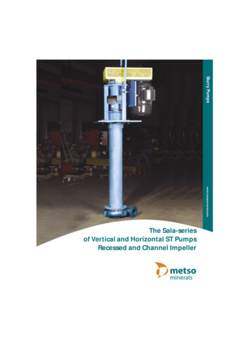
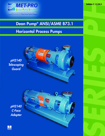
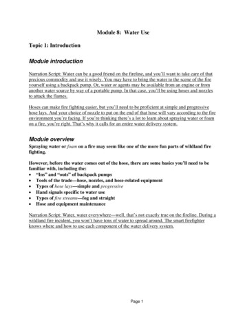
Definitions Overhung Impeller Type: The impeller is mounted on the end ofa shaft which is “overhung” from its bearing supports. Example:– Close Coupled pumps where the impeller is mounted directly on themotor shaft– Separately coupled or frame mounted where the impeller ismounted on a separate pump shaft supported by its own bearings. Impeller Between Bearings Type: The impeller is mounted on ashaft with the bearings at both ends. The impeller is mounted“between bearings”. Example:– Axial Split, Horizontal Split Case– Axial Split Vertical Split Case6
Overhung Impeller- Close Coupled7
Overhung Impeller, Frame Mounted8
Impeller Between Bearings: HorizontalSplit9
Impeller Between Bearings: Vertical Split10
Axial and Radial Flow Axial Flow Pump– The impeller pushes the liquid in a direction parallel to the pumpshaft.– Most of the pressure is developed propelling or lifting the vanes onthe liquid.11
Axial and Radial Flow Continued . Radial Flow Pump:– Pressure is developed principally by centrifugal force action.– The liquid enters at the center of the impeller and is directed outalong the impeller, perpendicular to the pump shaft.12
Operating Principals As mentioned earlier, Centrifugal pump relies on the centrifugalforce.When you swing a bucket of water around overyour head, you will find that as you increase thespeed, the bucket is pulled harder against yourarm. This pull on your arm is the centrifugal force.It makes no difference if you swing the buckethorizontal or vertical. If the speed is fast enough,then the water will remain on the bucket.13
Operation Principals continued. . If you punch a small hole on the bottom ofbucket, the water throws a stream and thedistance the water travels is proportionalto the centrifugal force. The same force that kept water in thebucket, is how the simple Centrifugalpump works.14
Operation Principals continued. . Centrifugal Pump consists of a rotatingimpeller inside a stationary volute (casing). Liquid enters the pump through the suctioninlet into the eye of the impeller. The speed of the rotating impeller thenforces the liquid out through the dischargenozzle.15
Operation Principals continued . The liquid enters the inlet of the centrifugal pump underatmospheric pressure, and flows into the eye of the impeller. The Centrifugal force exerted on the liquid by therotating impeller, moves the liquid away fromthe impeller eye and out along the impellervanes to their extreme tip where the liquid isthen forced against the inside walls of the voluteand out through the discharge of the pump. Due to the reduction of pressure occurringat pump inlet and impeller eye, liquid is drawninto the pump in continuous flow as it movesthrough the pump.16
Operation Principals continued . The shape of the volute casing is such that it is wider at the dischargepoint than where the liquid is first forced by the impeller against the volute.When the water from the impeller strikes theside of the volute, the velocity is increased.This accelerated motion is called “KineticEnergy”, which is the energy in motion.The shape of the volute permits the liquidto expand, which slows down the motionof the liquid. As soon as the liquid slowsdown inside the volute, Kinetic Energy istransformed into pressure. This pressurethen forces the liquid out of the pump dischargenozzle into the outlet pipe lines.17
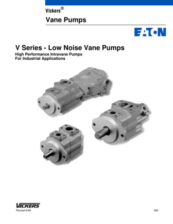
Nomenclature and Description18
Nomenclature and DescriptionContinued . The diagram shows the main parts of the centrifugal pump. The impeller is fastened to the shaft. The shaft passes through the pump casing and out through thestuffing box (portion of the casing through which the shaftextends and where seal or packing is placed). In order to keep the liquid from leaking out of the casingsbetween the stuffing box and the shaft, Packing or MechanicalSeal is used. The shaft is supported by two bearing housing and is thenconnected by a coupling installed between the pump shaft andthe motor shaft.19
Nomenclature and DescriptionContinued .20
Different Types of ImpellerThe impeller of a Centrifugal Pump can be of three types: Open Impeller: The vanes are cast free on both sides. Semi-Open Impeller: The vanes are free on one side andenclosed on the other. Enclosed Impeller: The vanes are located between the twodiscs, all in a single casting.21
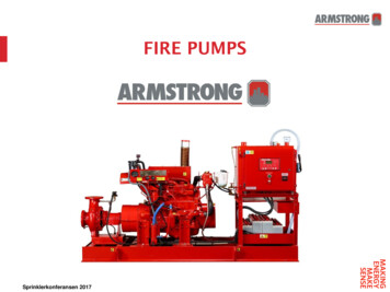
Centrifugal pump Curves- Characteristics Head and Capacity– A rating curve indicates the relationshipbetween the head (pressure) developedby the pump and the flow through thepump based on a particular speed andimpeller diameter when handling a liquid.– As the capacity increases, the total headwhich the pump is capable of developingdecreases.– In general, the highest head the Centrifugal Pump can develop is atthe point where there is no flow through the pump.22
Centrifugal pump Curves- CharacteristicsContinued . BHP (Brake Horsepower) and Capacity– For the Centrifugal pump to deliverthe capacity we want, we mustsupply the pump with a certain HP.– Generally, the HP increases as weincrease the capacity. BHP: is the total power required bya pump to do a specified amountof work.BHP Q x H x Sp.Gr3960 x Efficiency23
Centrifugal pump Curves- CharacteristicsContinued . Efficiencies– Efficiency of a pump can be calculated by:Eff Q x H x Sp.Gr x 1003960 x HPwhere,Eff Efficiency (%)Q Capacity delivered by the pumpH Head developed by the pumpSp. Gr Specific Gravity of liquid beingpumpedHP Horsepower required by the pump24
Centrifugal pump Curves- CharacteristicsContinued . 3960 is a constant linking a HP (33,000 ft lbs / min) to a USGPM (8.333 lbs). 33000 39608.33325
Centrifugal pump Curves- CharacteristicsContinued . NPSH and Capacity– The curve shows the relationship betweenthe capacity which the pump will deliverand the NPSH (net positive suction head),which is required for proper operationof the pump at that capacity.– Lack of NPSH measured in Feet ofthe liquid pumping, will cause the pumpto operate improperly and causecavitations.26
Centrifugal pump Curves- CharacteristicsContinued . Overall Rating– By plotting all the characteristics of a Centrifugal Pump on onecoordinate system, we can define the capabilities and limitations ofthe pump.27
Specific Speed Specific Speed is used to describe the geometry (shape) of apump impeller.– Performance of Centrifugal pump is expressed in terms of pumpspeed, total head and, required flow. Specific Speed is calculatedusing the formula below at pump’s BEP.– Formula: Specific Speed (Ns) N QN: speed of pump (rpm),H (3/4)Q: flow, H: head28
Specific Speed Continued .29
Centrifugal pump Curves- CharacteristicsContinued . System Curves– Pressure loss and Friction Loss Simple System with Point A and B on same level. Assume a line through which liquid is flowing and also assume heatexchangers, valves and other items which add to total friction loss. Friction loss through the system will increase as we increase thecapacity (velocity). Friction loss is proportional to the square of capacity. At zero flow, there is no friction loss.30
Centrifugal pump Curves- CharacteristicsContinued . Point B is higher than Point A. Necessary to add energy to the fluid to get to Point B from A. The amount of energy required is exactly equal to the differencein elevation between Point A and B, assuming friction loss asbefore.31
Centrifugal pump Curves- CharacteristicsContinued . Friction Curve will be the same in both systems because thefriction loss is the same. We just added constant amount of head at any capacity to getthe liquid from one point to another.32
Centrifugal pump Curves- CharacteristicsContinued . Assume pressure at Point A different than pressure at Point B. If we take suction at Point A from an open tank and discharge itat Point B in a closed tank, even though Point A and B are at thesame level, we must still overcome the differential pressurebetween both points.33
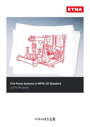
Centrifugal pump Curves- CharacteristicsContinued . Selecting a Pump– A system requires 275 GPM capacity through the system, delivers165 ft of head.– Performance curve shows 172 ft of head required.– The point of intersection between the pump’s performance curveand the system requirement curve represents the capacity at whichthe pump will operate.34
Affinity LawsAffinity Laws are the performance of Centrifugal Pumps based onchange in Speed, Power, Flow, Head, Impeller Diameter. FLOW CHANGES DIRECTLY AS A CHANGE IN SPEEDOR DIAMETER HEAD CHANGES AS THE SQUARE OF A CHANGE INSPEED OR DIAMETER HORSEPOWER CHANGES AS THE CUBE OF ACHANGE IN SPEED OR DIAMETER35
Affinity Laws Continued .Q1D1 Q2D2OR2Q1N1 Q2N2H1H1 D1 N1 OR D2 N2 H2H2BHP1 D1 D2 BHP232BHP1 N1 OR N2 BHP2336
Advantages and Disadvantages ofCentrifugal Pumps Centrifugal Pumps are the most widely used type of pump forthe transfer of liquids. There are many advantages anddisadvantages associated with Centrifugal Pumps: Advantages:–––––––Simple operation.Low first cost and maintenance.Insignificant excessive pressure build up in casing.Impeller and shaft are the only moving parts.Quiet operations.Wide range of pressure, flow and capacities.Utilize small floor space in different positions.37
Advantages and Disadvantages ofCentrifugal Pumps Continued . Disadvantages:– High viscous liquids are not handled well.– Centrifugal Pumps usually don’t have thecapabilities of handling high pressureapplications in comparison to other types ofpumps, i.e., Regenerative turbines.– In general, Centrifugal pumps cannot deliverhigh pressure without changes in design andare not suitable for high pressure delivery atlow volumes except the multistage pumps.38
Thank you for your timeand attention For questions andfurther informationplease visit our booth inthe exhibit hall.39
Centrifugal Pump- Definition Centrifugal Pump can be defined as a mechanical device used to transfer liquid of various types. As the name suggests, it relies on the principal of Centrifugal force. It converts the energy provided by a prime mover, such as an electric motor, steam turbine, or gasoline engine, to energy within the liquid being pumped. 3 Types of Pumps Pumps Positive .