Transcription
Intelligent Mold Tooling Design with Plastic Injection, CFD andStructural SimulationZhenhui Shen1, Jia Zheng2, Dongliang Hu3,Weijie Meng4, Zhonghua Jiao51: Shanghai MAHLE Thermal System Co., LtdE-mail: zhenhui.shen@smts-co.com2: Shanghai MAHLE Thermal System Co., LtdE-mail: Jia.zheng@smts-co.com3: Shanghai MAHLE Thermal System Co., LtdE-mail: Dongliang.Hu@smts-co.com4: CATIA China Business ConsultantE-mail: weijie.meng@3ds.com5: SIMULIA China Business ConsultantE-mail: zhong-hua.jiao@3ds.comAbstract: Mold Cooling channel design directly impacts the cooling efficiency, temperature uniformity,and cycle time, and is also one of the key factors which influences the overall quality of injectionmolded plastic products. In this paper, we describe a project involving the mold cooling designoptimization for the Impeller of a HVAC blower unit. Conventional cooling channel design is comparedand contrasted with a conformal cooling channel design. Conventional cooling channels havestraight-line channels which can easily be drilled. However, with increasing complexity of plastic partdesigns, these conventional channels are too inefficient and can result in long cycle times or worseinferior part quality by increasing part warpage. Conformal cooling uses channels that closely followthe contour of the part geometry and therefore can provide highly effective and uniform coolingthroughout the part. The complexity of machining the channels is solved thanks to AdditiveManufacturing (AM) techniques including laser sintering. Finally, the same blower design is included inthe whole HVAC product assembly and then validated by a frequency analysis.Keywords: Tooling design; Topology optimization; Additive manufacturing; Conformal cooling channel;Frequency analysis; 3DEXPERIENCE
1. IntroductionInjection molding is a widely used and accepted manufacturing process in the production of plasticparts (Suchana and Hazim, 2016). Filling, packing, cooling and ejection are the main phases. Coolingphase is a significant step among the three because it greatly affects the production rate and moldingquality (Hong-Seok, 2017). Design of mold cooling channel for plastic injection is of critical importancefor cooling efficiency, temperature uniformity and cycle time, and is also one of the key factors for thequality of the product. With the rising competition worldwide in automobile industry, cycle timereduction in plastic injection molding is attracting more and more attention. Conventional coolingchannels with straight drilled lines always manufactured by CNC are far from being efficient and resultin longer cooling cycle. At present, additive manufacturing (AM) can provide an opportunity tomanufacture intelligent mold tooling with conformal cooling channels that closely conform to thecontour of the part geometry. Conformal cooling channel made by additive manufacturing canprovide uniform cooling, highly cooling efficiency and reduce amount of warping (Lawrence, 2014).Additive manufacturing as a revolutionary technology also can provide economic manufacturing atvery low volumes and highly complexity geometry parts (Matrin, 2014), for example aerospace(Brandt, 2013), high-value jet engine (Halchak, 2012), and automotive components that areincompatible with traditional manufacturing methods (Cooper, 2012).The current work is concentrated on developing intelligent mold tooling insert with conformal coolingchannels for the impeller of a HVAC blower unit. The proposed conformal cooling channel design hasbeen validated and compared with conventional cooling channel design using two simulationproducts developed by Dassault Systemes on 3DEXPERIENCE Platform – Plastic Injection MoldEngineer (IME) and Fluid Mechanics Analyst (FLA). With FLA, a conjugate heat transfer CFD simulationwas performed to determine optimal coolant flow conditions (flow rate, temperature). The results ofFLA were then used to setup injection molding simulation in IME to validate the temperatureuniformity and part quality (warpage, volumetric shrinkage, pressure, etc.) aspects of theconventional and conformal cooling channel designs.With the assistance of Dassault Systemes 3DEXPERIENCE Functional Generative Designer (GDE) role,for the impeller project, we were able to obtain a topologically optimized conformal cooling channeldesign. Topology optimization refers to the search for geometry that optimizes an objective function,such as minimal mass or cost, subject to associated boundary conditions and constraints, such asapplied loads, allowable spatial envelope or maximum allowable stress (Sigmund, 2000).
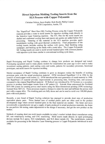
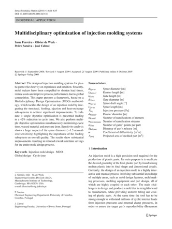
2. Design and simulationInsert #1-aInsert #1-bInsert #2-aBlower wheelInsert #2-bInsert #2-c(a) Milling (traditional)Insert #2-cInsert #1-aInsert #2-eInsert #2-aInsert #2-dInsert #2-bInsert #1-bBlower wheel(b) 3D printing (conformal)Fig.1 (a) CAD model with traditional cooling channel for traditional tooling; (b) CAD model withconformal cooling channel for 3D printingInjection molding is a popular method that is used to make plastic product due to high productivity.Fig.1 shows the injection molding system with traditional cooling channel and conformal coolingchannel for the impeller of a HVAC blower unit. Traditional cooling channel is straight drilled linesmanufactured by CNC shown in Fig.2 (a). Conformal cooling channel is produced by 3D printing inFig.2(b). All cooling channels are Ф8 mm. Steel is used for part-forming components of molds. Wateris selected as the coolant and its temperature at inlet is about 25 . The loop operates at an averageflow rate of 15 L/min.
(a)(b)Fig.2(a) traditional cooling circuits layout;(b) conformal cooling channel2.1 Injection filling simulationThe injection molding process includes three significant stages: filling stage, cooling stage and ejectionstage. Before we analyze the thermal performance of two cooling systems, filling simulation is carriedout in Moldflow and Dassault Systemes’ Plastic Injection Mold Engineer (IME) as the followingpictures shown in Fig.3. It’s clear that filling time is only about 4s, the melt temperature of material is230 . Material flow can be seen clearly during filling process. The filling time calculated by IME issimilar to that calculated by Moldflow.(a) Filling results from Moldflow(b) Filling reults from IMEFig.3 Filling simulation:(a) results from Moldflow; (b) results from 3DE IME2.2 Temperature distributionTransient cooling simulation is carried out to analyze the thermal performance of the two coolingsystems. The part temperature distribution of them is shown in Fig.4. As the pictures show that partcooled by conformal cooling channel provides better temperature distribution at the same coolingmoment. It can be concluded that conformal cooling channel provides higher cooling efficiency thantraditional cooling channel. Higher cooling efficiency always results in shorter cooling time (t 8.821s).
(a) traditional(b) conformal cooling channelFig.4. Comparison of part temperature distribution:(a) traditional and (b) conformal cooling channelFig.5 shows the part ejection temperature distribution of two cooling systems calculated by MoldFlow.From the following pictures, part ejection temperature distribution is more uniform, and its maximumtemperature is much lower cooled by conformal cooling channel than that cooled by traditionalcooling channel. It also shows that conformal cooling channel is more efficient.(a) Conventional(b) 3D printingFig.5 Part ejection temperature distribution (a) conventional tooling systems; (b) 3Dprinting tooling systemsAfter checking part temperature distribution of two cooling systems, we also checked the moldtemperature distribution of the two systems in STAR-CCM , Moldflow and 3DEXPERIENCE PlasticInjection Mold Engineer (IME). Fig.6 shows the mold temperature distribution from STAR-CCM , it’sclear that mold with conformal cooling channel gives better temperature distribution. Thetemperature at traditional mold center is almost unchanged after 60s cooling. It can be concludedthat conformal cooling channel provides better mold cooling
(a) conventional(b) 3D printingFig.6 Mold temperature distribution (a) traditional mold with straight line; (b) 3DPrinting mold with conformal cooling channel2.3 Coolant flow simulationCoolant flow simulation was conducted using Fluid Mechanics Analyst (FLA) role on 3DEXEPRIENCE tovalidate thermal performance of the conformal cooling channel system. The CFD results from FluidMechanics Analyst were benchmarked with Star-CCM , and were found to be equally accurate. Theinitial temperature of mold is set to 90 and the coolant is 25 . The loop is used with an averageflow rate of 15L/min, and the Reynolds number of coolant water is 10000.Mold temperature distribution is shown in Fig.7. As shown in the images below, result from FluidMechanics Analyst is very similar to that of STAR-CCM at 60s.(a) 3DEXPERIENCE Fluid Mechanics Analyst(b) STAR-CCM Fig.7 Mold temperature distribution at 60s: (a) 3DEXPERIENCE Fluid Analyst; (b) STAR-CCM Similarly, the coolant temperature is shown in Fig.8. It also shows that coolant temperaturedistribution from Fluid Mechanics Analyst is very similar to that of STAR-CCM at 60s. It can beinferred that CFD simulation results from Fluid Mechanics Analyst are comparable to that ofSTAR-CCM .
(a) 3DEXPERIENCE Fluid Mechanics Analyst(b) STAR-CCM Fig.8 Coolant temperature distribution at 60s: (a) FLA on 3DEXPERIENCE; (b) STAR-CCM 2.4. Structural ValidationThe same blower unit design has been included in the whole HVAC product assembly and afrequency analysis is carried out using Structural Analysis Engineer (DRD) role (Figure 9). Themodel preparation time is largely reduced thanks to the automatic solid meshing andautomatic detecting capability for creating tie connections. And, blower design changes canbe revalidated easily simply by replacing the old geometry with the new ones.Fig. 9 (a) HVAC assembly(b) Frequency analysis results3. Thermal imager checkAfter running simulation to check part and mold temperature distribution of two cooling systems,thermal imager is used to check the temperature distribution of real part and real mold. Fig.10 (a) and(b) show the temperature distribution of products after ejection by thermal imager of traditional and3D printing injection systems. The impeller of a HVAC blower unit manufactured by intelligent moldtooling system is cooled more uniform and efficiency. The maximum ejection temperature of impellercan be reduced from 53 to 33 with conformal cooling channel. Highlight areas by traditionalcooling process have impact on dynamic unbalance behaviour and uneven cooling effects may causeappearance problems.
(a) Traditional(Product)(b) conformal cooling channel (Product)Fig.10 Comparison of product temperature distribution after ejection by thermal imagerSimilarly, Fig.11 (c)-(f) show the mold temperature distribution of traditional and 3D printing bythermal imager. The results show mold with conformal cooling channel gives better temperaturedistribution and its temperature difference is much smaller compared with that of traditional coolingchannel. It also shows that conformal cooling channel requires less time to cooling down intelligentmold to ambient temperature.(c) Traditional (Cavity)(d) conformal cooling channel (Cavity)(e) Traditional (Core)(f) conformal cooling channel (Core)Fig.11 Comparison of mold temperature distribution during cooling process by thermal imager4. Topology optimizationFrom the above simulation and testing process, the desirable shape of an intelligent mold withconformal cooling channel has been confirmed. The intelligent mold can provide higher coolingefficiency and more uniform cooling. This section is to run topology optimization on it to minimize itsweight in 3DEXPERIENCE GDE. The original and optimized model is shown in Fig.12 (a) and (b),respective. After topology optimization the total mass reduction is about 20%.
The next is to perform CAD reconstruction which is a time-consuming job in the past. Now with thehelp of the integrated CATIA Bionic Molding tool, the smoothed model could be quickly built in lessthan one hour, showing in the following Fig.12 (c)(a) Original model(b) Optimized model(c) smoothed modelFig.12 Design created by 3DEXPERIENCE GDE: (a) original model; (b) optimized model beforegeometry reconstruction; (c) optimized model after smoothing geometry5. ConclusionBased on the completed process, an alternative method that provides a conformal cooling channelsystem has been proposed. 3D printing conformal channel ensures that the part is cooled moreuniformly as well as more efficiently. The appearance and unbalance behavior of the injection partwith conformal cooling channel is slight better. Topology optimization was carried out in3DEXPERIENCE Functional Generative Designer (GDE) to reduce the mass of the mold. In thetraditional workflow, we designed the mold in Unigraphics and then transferred the data toSTAR-CCM , Moldflow and Tosca for one design cycle. The Tosca results were then converted to UGfor iterative design. When several design and modify cycles are involved, this process is inherentlyinefficient and carries the risk of data corruption during the numerous data conversion steps.However, when deploying the same workflow on the 3DEXPERIENCE Platform, there is almost no dataconversion problem, access to state-of-the-art CAD-embedded-simulation tools and it’s much moreconvenient to carry out iterative design while exploring multiple variants in a single collaborativeplatform. It’s a powerful tool enabling faster design cycle, enhanced product quality, freedom toinnovate, reduced protyping and significant reduction in the overall cost of the end product6. Further workTo reduce repeated manual work during geometry reconstruction, we would like to have fullyautomated assistance. The thermal performance and structural strength of optimized conformalcooling channel need be validated.AcknowledgementsThe authors wish to express their thanks to Srikrishna Chittur, Murali Annareddy, Wen-Jun He, WeiJie Lin from Dassault Systemes for their gracious support.7.Reference[1] Suchana A, Jahan, Hazim El-Mounayri. Optimal conformal cooling channels in 3D printed dies forplastic injection molding. Procedia Manufacturing,2016,5:888-900
[2] Hong-Seok Park, Xuan-Phuong Dang. Development of a smart plastic injection mold withconformal cooling channels. Procedia Manufacturing 2017;10;48-59[3] Lawrence E. Murr. Additive Manufacturing: Changing the Rules of Manufacturing. Handbook ofMaterials Structures, Properties, Processing and Performance. 2014[4] Martin Leary, Luigi Merli, Federico Torti, Maciej Mazur, Milan Brandt. Optimal topology foradditive manufacture: A method for enabling additive manufacture of support-free optimal structures.Materials and Design,2014,63:678-690[5] Brandt M, Sun S, Leary M, Feih S, Elambasseril J, Liu Q. High-value SLM aerospace components:from design to manufacture. Adv Mater Res 2013;633:135-47.[6] Halchak J, Wooten J, McEnerney B. Layer build of titanium alloy complex-geometry componentsfor rocket engines.In:Ti 2011 – Proceedings of the 12th world conference on titanium,Beijing,China;2012,3:1715-8[7] Cooper DE, Stanford M, Kibble KA, Gibbons GJ. Additive manufacturing for product improvementat Red Bull Technology. Mater Des 2012;41:223-30.[8] Sigmund O. Topology optimization: a tool for the tailoring of structures and materials. Philos TransR SOC A Math Phys Eng Sci 2000;358(1765);211-27
Injection molding is a widely used and accepted manufacturing process in the production of plastic parts (Suchana and Hazim, 2016). Filling, packing, cooling and ejection are the main phases. Cooling phase is a significant step among the three because it greatly affects the production rat