Transcription
CareSoft Series Metered Water SoftenersFor Models: UCS-844 UCS-948 UCS-1044 UCS-1054 UCS-1248 UCS-1354
TABLE OF CONTENTSPreinstallation Instructions for Dealers . . . . . . . . . . . . . . . . . . . . . . . . . . . . . . . . . . 3Bypass Valve . . . . . . . . . . . . . . . . . . . . . . . . . . . . . . . . . . . . . . . . . . . . . . . . . . . . . . . 4Installation . . . . . . . . . . . . . . . . . . . . . . . . . . . . . . . . . . . . . . . . . . . . . . . . . . . . . . . . 5-6Programming Procedures . . . . . . . . . . . . . . . . . . . . . . . . . . . . . . . . . . . . . . . . . . . 7-8Operating Displays and Instructions . . . . . . . . . . . . . . . . . . . . . . . . . . . . . . . . . . 9-10Start-up Instructions . . . . . . . . . . . . . . . . . . . . . . . . . . . . . . . . . . . . . . . . . . . . . . 11-12Troubleshooting Guide . . . . . . . . . . . . . . . . . . . . . . . . . . . . . . . . . . . . . . . . . . . . 13-16Replacement Parts . . . . . . . . . . . . . . . . . . . . . . . . . . . . . . . . . . . . . . . . . . . . . . . . 17-25Specifications . . . . . . . . . . . . . . . . . . . . . . . . . . . . . . . . . . . . . . . . . . . . . . . . . . . . . . 26Warranty . . . . . . . . . . . . . . . . . . . . . . . . . . . . . . . . . . . . . . . . . . . . . . . . . . . . . . . . . 27Quick Reference Guide . . . . . . . . . . . . . . . . . . . . . . . . . . . . . . . . . . . . . . . . . . . . . . 28YOUR WATER TESTHardnessIronpH*NitratesManganeseSulphurTotal Dissolved Solidsgpgppmnumberppmppmyes/no*Over 10 ppm may be harmful for human consumption.Water conditioners do not remove nitrates or coliform bacteria,this requires specialized equipment.Your CareSoft Pro Series water conditioners are precision built, high quality products. These units will deliverconditioned water for many years to come, when installed and operated properly. Please study this manual carefullyand understand the cautions and notes before installing. This manual should be kept for future reference. If you haveany questions regarding your water conditioner, contact your local dealer or WaterCare at the following:1900 Prospect Court Appleton, WI 54914Phone: 920-682-6823 Fax: 920-682-7673
PREINSTALLATION INSTRUCTIONS FOR DEALERS:The manufacturer has preset the water treatment unit’s sequence of cycles, cycle times, salt dose, exchange capacity andsalt dose refill time.The dealer should read this page and guide the installer regarding hardness, day override, time of regeneration,service alarm and buzzer alarm settings before installation.For the installer, the following must be used: Program Installer Settings . Hardness, Day Override (preset to 6 days), Time of Regeneration (preset to 2a.m., with brine tank refill to occur four hours prior; see Operating Displays and Instructions for more details),Service Alarms (preset to “OFF”) and Buzzer Alarm (preset to start at 6 a.m. and end at 10 p.m.) Read Normal Operating Displays Set Time of Day Read Power Loss & Error Display Be sure system and installation are in compliance with all state and local laws and regulations.For the homeowner, please read Programming Procedures and Operating Displays and Instructions.During operation, the normal user display is time of day and gallons per minute.Flow Rate, Vacation Mode, Capacity Remaining and Days to a Regeneration are optional displays but are not normallyused. (Vacation Mode is used only when there will be no water usage for an extended period of time. Once 50 gallonsof water is used, the unit will automatically regenerate that night and resume normal operation.) Each of these can beviewed by pressing NEXT to scroll through them. When stepping through any programming, if no buttons are pressedwithin 5 minutes, the display returns to a normal user display. Any changes made prior to the 5 minute time out areincorporated. To quickly exit any Programming, Installer Settings, etc., press SET CLOCK. Any changes made prior to theexit are incorporated.If desired, two regenerations within 24 hours are possible with a return to the preset program. To do a doubleregeneration:1. Press the REGEN button once. “REGEN TODAY” will flash on the display.2. Press and hold the REGEN button for three seconds until a regeneration begins.Once the valve has completed the immediate regeneration, the valve will regenerate one more time at the preset.3
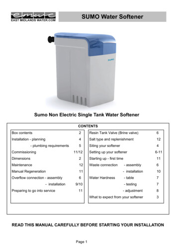
BYPASS VALVE:The bypass valve is typically used to isolate the control valve from the plumbing system’s water pressure in order to perform controlvalve repairs or maintenance. The 1” full flow bypass valve incorporates four positions, including a diagnostic position that allowsa service technician to have pressure to test a system while providing untreated bypass water to the building. Be sure to installbypass valve onto main control valve, before beginning plumbing. Or, make provisions in the plumbing system for a bypass. Thebypass body and rotors are glass-filled Noryl and the nuts and caps are glass-filled polypropylene. All seals are self-lubricatingEPDM to help prevent valve seizing after long periods of non-use. Internal “O” Rings can easily be replaced if service is required.The bypass consists of two interchangeable plug valves that are operated independently by red arrow shaped handles. Thehandles identify the direction of flow. The plug valves enable the bypass valve to operate in four positions.1. NORMAL OPERATION POSITION: The inlet and outlet handles point in the direction of flow indicated by the engravedarrows on the control valve. Water flows through the control valve for normal operation of a water softener. Duringthe regeneration cycle this position provides regeneration water to the unit, while also providing untreated water to thedistribution system (Fig. 1).2. BYPASS POSITION: The inlet and outlet handles point to the center of the bypass. The system is isolated from the waterpressure in the plumbing system. Untreated water is supplied to the building (Fig. 2).3. DIAGNOSTIC POSITION: The inlet handle points toward the control valve and the outlet handle points to the center ofbypass valve. Untreated supply water is allowed to flow to the system and to the building, while not allowing water to exitfrom the system to the building (Fig. 3). This allows the service technician to draw brine and perform other tests without thetest water going to the building.NOTE: The system must be rinsed before returning the bypass valve to the normal position.4. SHUT OFF POSITION: The inlet handle points to the center of the bypass valve and the outlet handle points away fromthe control valve. The water is shut off to the building. The water treatment system will depressurize upon opening a tap inthe building. A negative pressure in the building combined with the softener being in regeneration could cause a siphoningof brine into the building. If water is available on the outlet side of the softener, it is an indication of water bypassing thesystem (Fig. 4) (i.e. a plumbing cross-connection somewhere in the building).NORMALOPERATIONPOSITIONBYPASS POSITIONDIAGNOSTICPOSITIONSHUT OFFPOSITIONFIGURE 1FIGURE 2FIGURE 3FIGURE 44
INSTALLATION:GENERAL INSTALLATION & SERVICE WARNINGSThe control valve, fittings and/or bypass are designed to accommodate minor plumbing misalignments. There is a smallamount of “give” to properly connect the piping, but the water softener is not designed to support the weight of the plumbing.Do not use Vaseline, oils, other hydrocarbon lubricants or spray silicone anywhere. A silicone lubricant may be used on black“O” Rings, but is not necessary. Avoid any type of lubricants, including silicone, on red or clear lip seals.Do not use pipe dope or other sealants on threads. Teflon tape must be used on the threads of the 1” NPT inlet and outlet, thebrine line connection at the control valve, and on the threads for the drain line connection. Teflon tape is not used on the nutconnections or caps because “O” Ring seals are used. The nuts and caps are designed to be unscrewed or tightened by handor with the special plastic Service Wrench, #CV3193-02. If necessary pliers can be used to unscrew the nut or cap. Do notuse a pipe wrench to tighten nuts or caps. Do not place screwdriver in slots on caps and/or tap with a hammer.SITE REQUIREMENTSwater pressure – 25-100 psiwater temperature – 33-100 F (0.5-37.7 C)electrical – 115/120V, 60Hz uninterrupted outlet current draw is 0.5 amperes the plug-in transformer is for dry locations only the tank should be on a firm level surfaceWELL WATER INSTALLATIONMUNICIPAL INSTALLATION1. The distance between the drain and the water conditioner should be as short as possible.2. Since salt must be periodically added to the brine tank, it should be located where it is easily accessible.3. Do not install any water conditioner with less than 10 feet of piping between its outlet and the inlet of a water heater.4. Do not locate unit where it or its connections (including the drain and overflow lines) will ever be subjected to roomtemperatures under 33 F.5. Do not subject the tank to any vacuum, as this may cause an “implosion” and could result in leaking. If there is a possibilitya vacuum could occur, please make provision for a vacuum breaker in the installation.6. INLET/OUTLET PLUMBING: Be sure to install Bypass Valve onto main control valve before beginning plumbing.Make provisions to bypass outside hydrant and cold hard water lines at this time. Install an inlet shutoff valve and plumbto the unit’s bypass valve inlet located at the right rear as you face the unit. There are a variety of installation fittingsavailable. They are listed under Installation Fitting Assemblies, page 26-27. When assembling the installation fittingpackage (inlet and outlet), connect the fitting to the plumbing system first and then attach the nut, split ring and “O” Ring.Heat from soldering or solvent cements may damage the nut, split ring or “O” Ring. Solder joints should be cool andsolvent cements should be set before installing the nut, split ring and “O” Ring. Avoid getting solder flux, primer, andsolvent cement on any part of the “O” Rings, split rings, bypass valve or control valve. If the building’s electrical systemis grounded to the plumbing, install a copper grounding strap from the inlet to the outlet pipe. Plumbing must be done inaccordance with all applicable local codes.5
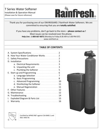
7. INSTALLING GROUND: To maintain an electrical ground in metal plumbingof a home’s cold water piping (such as a copper plumbing system), install aground clamp or jumper wiring.NOTE: If replacing an existing softener, also replace the ground clamps/wire.If removing a softener, replace the piping with the same type of piping as theoriginal to assure plumbing integrity and grounding.8. DRAIN LINE: First, be sure that the drain can handle the backwash rate of the system. Solder joints near the drain mustbe done prior to connecting the drain line flow control fitting. Leave at least 6” between the drain line flow control fittingand solder joints. Failure to do this could cause interior damage to the flow control. Install a 1/2” I.D. flexible plastic tubeto the Drain Line Assembly or discard the tubing nut and use the 3/4” NPT fitting for rigid pipe (recommended).If the backwash rate is greater than 7 gpm, use a 3/4” rigid drain line. Where the drain line is elevatedbut empties into a drain below the level of the control valve, form a 7” loop at the discharge end of the line so that thebottom of the loop is level with the drain connection on the control valve. This will provide an adequate anti-siphon trap.Piping the drain line overhead 10 ft is normally not a problem. Be sure adequate pressure is available (40-60 psi isrecommended). Where the drain empties into an overhead sewer line, a sink-type trap must be used. Run drain tube to itsdischarge point in accordance with plumbing codes. Pay special attention to codes for air gaps and anti-siphon devices.NOTE: Drain line nut will not be supplied for units having a backwash rate greater than 7 gpm.TYPICAL DRAIN LINE INSTALLATIONS9. BRINE TANK CONNECTION: Install the 3/8” O.D. polyethylene tube from the Refill Elbow to the Brine Valve in thebrine tank.10. OVERFLOW LINE CONNECTION: An overflow drain line is recommended where a brine overflow could damagefurnishings or the building structure. Your softener is equipped with a brine tank safety float which greatly reducesthe chance of an accidental brine overflow. In the event of a malfunction, however, an overflow line connection willdirect the “overflow” to the drain instead of spilling on the floor where it could cause considerable damage. Thisfitting is an elbow on the side of the brine tank. Attach a length of 1/2” I.D. tubing to fitting and run to drain. Do notelevate overflow line higher than 3” below bottom of overflow fitting. Do not “tie” this tube into the drain line of thecontrol valve. Overflow line must be a direct, separate line from overflow fitting to drain, sewer, or tub. Allow an airgap as per the drain line instructions.CAUTION: Never insert a drain line into a drain, sewer line, or trap. Always allowan air gap between the drain line and the wastewater to prevent thepossibility of sewage being back-siphoned into the conditioner.6
PROGRAMMING PROCEDURES:1. Set time of day:Time of day should only need to be set after extended power outages or when daylight saving time begins or ends. If anextended power outage occurs, the time of day will flash on and off indicating that the time should be reset.STEP 1 – PressCLOCK.STEP 2 – CURRENT TIME (HOUR): Set the hour of the day using or — buttons. AM/PM toggles after 12.Press NEXT to go to step 3.STEP 3 – CURRENT TIME (MINUTES): Set the minutes using or — buttons. If it is desired to back up to theprevious step press REGEN button once. Pressing NEXT will exit CLOCK and return to the general operatingdisplay (page 9).1232. Programming:NOTE: The manufacturer has preset the unit so that the gallons between regenerations will be automatically calculatedafter the hardness is entered.STEP 1 – PressNEXTand simultaneously for 3 seconds.1STEP 2 – HARDNESS: Set the amount of hardness in grains per gallon (default 20)using the or — buttons. The allowable range is from 1 to 150 in 1 grainincrements.NOTE: If a resin media is used in the softener, increase the grains pergallon if soluble iron is present (1 ppm 4 gpg). This display will show“–nA– (not available)” if “FILTER” is selected or if “AUTO” is not factory set.PressPress2to go to step 3.REGEN if you want to exit.NEXTSTEP 3 – DAY OVERRIDE: The manufacturer has factory set 12 DAYS as thedefault. This is the maximum number of days between regenerations.If this is set to “OFF”, regeneration initiation is based solely on gallonsused. If any number is set (allowable range from 1 to 28), a regenerationinitiation will be called for on that day even if a sufficient number ofgallons were not used to call for a regeneration.Set Day Override using or — buttons (12 is recommended): set number of days between regeneration (1 to 28); or set to “OFF”.PressPressNEXTto go to step 4.if you need to return to the previous step.REGENSTEP 4 – REGENERATION HOUR: The manufacturer has factory set 2:00 A.M.as the default. This is the hour of day for regeneration and can be reset byusing or — buttons. “AM/PM” toggles after 12. The default time is 2:00a.m. (recommended for a normal household).PressPress3NEXTto go to step 5.if you need to return to the previous step.REGEN74
STEP 5 – REGENERATION MINUTES: Set the minutes using or — buttons.Press NEXT to exit installer programming. Press REGEN if you need toreturn to the previous step. To initiate an immediate manual regeneration,press and hold the REGEN button for three seconds. The system will beginto regenerate immediately. The control may be manually stepped throughthe regeneration cycles by pressing REGEN.STEP 6 – BACKLIGHT DISPLAY CONTROL: Set the display backlight on or offusing or — buttons. In the OFF position, the backlight will turn off after5 minutes of inactivity.856
OPERATING DISPLAYS AND INSTRUCTIONS:1. GENERAL OPERATION: When the system is operating, one of three displaysmay be shown. Pressing NEXT will alternate between the displays. One ofthe displays is always the current time of day. The second display shows thecurrent treated water flow rate through the system in Gallons Per Minute. Thethird display is one of the following: days remaining or volume remaining.Days remaining is the number of days left before the system goes through aregeneration cycle. Capacity remaining is the gallons that will be treated beforethe system goes through a regeneration cycle. The user can scroll between thedisplays as desired.GENERAL OPERATION DISPLAYSIf a water meter is installed, the word “Softening” or “Filtering” flashes on thedisplay when water is being treated (i.e. water is flowing through the system).2. REGENERATION MODE: Typically a system is set to regenerateat a time of no water use. If there is a demand for water when the systemis regenerating, untreated water will be delivered. When the system beginsto regenerate, the display will change to include information about thestep of the regeneration process and the time remaining for that step to becompleted. The system runs through the steps automatically and will reset itselfto provide treated water when the regeneration has been completed.3. MANUAL REGENERATION: Sometimes there is a need to regenerate beforethe control valve calls for it. This may be needed if a period of heavy water useis anticipated or when the system has been operated without salt.REGENERATION MODEMANUAL REGENERATION To initiate a manual regeneration at the next preset regeneration time, pressand release REGEN. The words “REGEN TODAY” will flash on the displayto indicate that the system will regenerate at the next regeneration time (setin Programming, steps 4 and 5). If you pressed the REGEN button in error,pressing the button again will cancel the command. To initiate a manual regeneration immediately, press and holdthe REGEN button for three seconds. The system will begin to regenerateimmediately. This command cannot be cancelled.Once a manual regeneration is initiated, the unit will go into the FILL position. Thisposition allows water to enter the brine tank until it reaches the proper level. Oncethis position is complete, you will notice a 240 Minute (4 hours) SOFTENINGposition. This 4-hour window allows the salt to dissolve and achieve proper brinestrength. During these FILL and SOFTENING positions, you will have softenedwater available for use. Once the unit advances to the BACKWASH positionand subsequent positions thereafter (see Start Up Instructions for regenerationsequence), the water softener will deliver water, but it will be untreated.IMPORTANT: With the Dry Salt Storage Feature, the brine tank will refill 4 hoursbefore the actual regeneration occurs. You may experience a small amount ofnoise for a short period of time at 10:00 p.m. (with typical setting) on the nightthat regeneration is to occur. This noise is only the brine tank filling and at no timeduring this process will you be without treated water.4. POWER LOSS AND BATTERY REPLACEMENT: The AC transformer comes witha 15 foot power cord and is designed for use with the control valve; the transformershould only be used in a dry location.In the event of a power outage that is less than 24 hours, the control valve willremember all settings and time of day. After 24 hours, the only item that needs tobe reset is the time of day and will be indicated by the time of day flashing. Allother settings are permanently stored in the nonvolatile memory.If a power loss occurs that is less than 24 hours and the time of day flashes, thisindicates that the battery is depleted. The time of day should be reset and thenon-rechargeable battery should be replaced. The battery is a 3 Volt Lithium CoinCell type 2032 and is readily available at most stores. To access battery location,remove front cover (see diagram on page 14 for battery location).9BATTERY REPLACEMENT
5. ERROR MESSAGE: If the word “ERROR” and a number are alternatelyflashing on the display record the number and contact the dealer for help.This indicates that the control valve was not able to function properly.ERROR6. BRINE TANK MAINTENANCE AND SALT: Refill the brine tank asnecessary, making sure at least 1/3 of the brine tank is full at all times.Without proper salt levels, the water softener may not operate properly.Because “typical” settings of this water softener include a dry salt storagefeature (no water in brine tank between regeneration), the manufacturer recommends the use of solar salt for bestresults. The brine tank is manufactured for the use of solar, pellets or rock salt. Do not use block salt. If pellet orrock salt is used, a cleaning of the brine tank every six months is recommended. If the dry salt storage feature is notbeing utilized, block salt may be used.CAUTION: With some models the manufacturer does NOT recommend the use ofany resin cleaners, nor placing any resin cleaners into the brine tank.Furthermore, do not use any salt that indicates it is an iron cleaning saltor that contains any cleaning additives. This may be harmful to the watersoftener and for human consumption. Consult dealer for proper cleaninginstructions and agents.10
START-UP INSTRUCTIONS:FLUSHING OF SYSTEM:To flush the system of any debris and air after installation is complete, please perform the following steps:1. Rotate bypass handles to the bypass mode (see Fig. 2 of page 4).2. Turn on inlet water and check for leaks in the newly installed plumbing.3. Fully open a cold water faucet, preferable at a laundry sink or bathtub without an aerator.4. Wait two to three minutes or until water runs clear, then turn water off and followstart-up instructions.System regeneration sequence is in the following order. (If it is desired to change this sequence, please refer to the DealerManual or contact the manufacturer.)1)2)3)4)5)6)BRINE TANK REFILL4 HOURS (240 minutes) OF SOFTENING MODE WHILE SALT IS DISSOLVINGBACKWASHBRINE DRAW AND SLOW RINSEFAST RINSEEND (return to service)The system is now ready for filling with water and for testing.1. With the softener in the bypass mode (Fig. 2 on page 4) and the control valve in normal operation where thedisplay shows either the time of day or the gallons remaining, manually add 3” of water to the regenerant tank.NOTE: If too much water is put into the brine tank during softener start up, it could result in a “salty water” complaintafter the first regeneration.During the first regeneration the unit will draw out the initial volume of brine/regenerant and refill it with the correctpreset amount.2. With the softener in bypass mode, press and hold the REGEN button until the motor starts. Release button. The displayreads “FILL” and the remaining time in this step is counting down. Since the regenerant tank was already filled inStep 1 press REGEN again and the display will read SOFTENING 240 (During a full regeneration this will be a 4hour period for salt to dissolve). Press REGEN again to put the valve into “BACKWASH.” Once valve has stoppedin position, unplug the transformer so that the valve will not cycle to the next position. Open the inlet handle of thebypass valve very slightly allowing water to fill the tank slowly in order to expel air.CAUTION: If water flows too rapidly, there will be a loss of media to the drain.3. When the water is flowing steadily to the drain without the presence of air, slowly open the inlet valve. Restore powerand momentarily press the REGEN button to advance the control to the “BRINE” position.4. The bypass is now in the diagnostic mode (Fig. 3 on page 4). Check to verify that water is being drawn fromregenerant tank with no air leaks or bubbles in the brine line. There should be a slow flow to the drain.5. Momentarily press REGEN again until the display reads “RINSE.” There should be a rapid flow to the drain. Unplugtransformer to keep the valve in the “RINSE” position. Allow to run until steady, clear and without air. While the unitis rinsing, load the brine tank with water softener salt (refer to page 9, Brine Tank Maintenance and Salt).Restore power.6. Place bypass valve in the normal operating mode (Fig. 1 on page 4) by opening the outlet bypass handle. PressREGEN and the unit will return to the service position with time of day being displayed.7. CONDITIONING OF MEDIA:To flush any remaining debris and air from the system again:1. Full open a cold water faucet, preferably at a laundry sink or bathtub without an aerator.2. Wait two to three minutes or until water runs clear, then turn water off.3. Turn on hot water and check for air, then turn water off after air is discharged.11
8. SANITIZING OF UNIT UPON INSTALLATION AND AFTER SERVICE:At this time, it is advised to sanitize the softener:1. Open brine tank and remove brine well cover.2. Pour 1 oz. of household bleach into the softener brine well.3. Replace brine well cover.NOTE: Avoid pouring bleach directly onto the safety float components in the brine well.Unit sanitizing will be complete when the first cycle is run and the bleach is flushed from the softener.9. Check time of day. Start-up is now complete.12
TROUBLESHOOTING GUIDE:PROBLEM1. No display onPC board2. PC board does notdisplay correct timeof day3. Display does notindicate that water isflowing. Refer to userinstructions for how thedisplay indicates wateris flowing.4. Control valveregenerates at wrongtime of day5. Time of day flashes onand offCAUSECORRECTIONA. No power at electric outletA. Repair outlet or use working outletB. Control valve power adapter not plugged intooutlet or power cord end not connected to PCboard connectionB. Plug power adapter into outlet or connectpower cord end to PC board connectionC. Improper power supplyC. Verify proper voltage is being delivered toPC boardD. Defective power adapterD. Replace power adapterE. Defective PC boardE. Replace PC boardF. Dead batteryF. Replace batteryA. Power adapter plugged into electric outletcontrolled by light switchA. Use uninterrupted outletB. Tripped breaker switch and/or tripped GFIB. Reset breaker switch and/or GFI switchC. Power outageC. Reset time of day. If PC board has batteryback up present the battery may be depleted.See front cover and drive assembly drawingfor instructions.D. Defective PC boardD. Replace PC boardA. Bypass valve in bypass positionA. Turn bypass handles to place bypass inservice positionB. Meter is not connected to meter connection onPC boardB. Connect meter to three pin connection labeledMETER on PC boardC. Restricted/stalled meter turbineC. Remove meter and check for rotation orforeign materialD. Meter wire not installed securely into threepin connectorD. Verify meter cable wires are installed securelyinto three pin connector labeled METERE. Defective meterE. Replace meterF. Defective PC boardF. Replace PC boardA. Power outageA. Reset time of day. If PC board has batteryback up present the battery may be depleted.See front cover and drive assembly drawingfor instructions.B. Time of day not set correctlyB. Reset to correct time of dayC. Time of regeneration set incorrectlyC. Reset regeneration timeD. Control valve set at “on 0” (immediateregeneration)D. Check programming setting and reset toNORMAL (for a delayed regen time)E. Control valve set at “NORMAL on 0”(delayed and/or immediate)E. Check programming setting and reset toNORMAL (for a delayed regen time)A. Power outageA. Reset time of day. If PC board has batteryback up present the battery may be depleted.See front cover and drive assembly drawingfor instructions.6. Control valve does notregenerate automatically A. Broken drive gear or drive cap assemblywhen the correct button(s)is depressed and held.B. Broken piston rodFor timeclock valves thebuttons are & .For all other valves theC. Defective PC boardbutton is REGEN.13A. Replace drive gear or drive cap assemblyB. Replace piston rodC. Defective PC board
TROUBLESHOOTING GUIDE cont’d:PROBLEM7. Control valve does notregenerate automaticallybut does when thecorrect button(s) isdepressed and held.For timeclock valves thebuttons are & .For all other valves thebutton is REGEN.8. Hard or untreatedwater is beingdelivered9. Control valve uses toomuch regenerant10. Residual regenerantbeing delivered toservice11. Excessive water inregenerant tankCAUSECORRECTIONA. Bypass valve in bypass positionA. Turn bypass handles to place bypass inservice positionB. Meter is not connected to meter connection onPC boardB. Connect meter to three pin connection labeledMETER on PC boardC. Restricted/stalled meter turbineC. Remove meter and check for rotation orforeign materialD. Incorrect programmingD. Check for programming errorE. Meter wire not installed securely into threepin connectorE. Verify meter cable wires are installed securelyinto three pin connector labeled METERF. Defective meterF. Replace meterG. Defective PC boardG. Replace PC boardA. Bypass valve is open or faultyA. Fully close bypass valve or replaceB. Media is exhausted due to high water usageB. Check program settings or diagnostics forabnormal water usageC. Meter not registeringC. Remove meter and check for rotation orforeign materialD. Water quality fluctuationD. Test water and adjust programvalues accordinglyE. No regenerant or low level of regenerant inregenerant tankE. Add proper regenerant to tankF. Control fails to draw in regenerantF. Refer to Troubleshooting Guide number 12G. Insufficient regenerant level in regenerant tankG. Check refill setting in programming. Checkrefill flow control for restrictions or debris andclean or replaceH. Damaged seal/stack assemblyH. Replace seal/stack assemblyI. Control valve body type and piston typemix matchedI. Verify proper control valve bod
6 7. INSTALLING GROUND: To maintain an electrical ground in metal plumbing of a home's cold water piping (such as a copper plumbing system), install a ground clamp or jumper wiring. NOTE: If replacing an existing softener, also replace the ground clamps/wire. If removing a softener, replace the piping with the same type of piping as the