Transcription
T Series Water SoftenerInstallation & Operation Manual(Please save for future reference)Thank you for purchasing one of our ENVIROGARD / Rainfresh Water Softeners. We arecommitted to ensuring that you are totally satisfied.If you have any problems, don’t go back to the store – please contact us !Most issues can be resolved over the phone.Help Line : 1-800-667-8072 (Monday to Friday 8:30 AM to 5:00 PM EST)www.rainfresh.caTABLE OF CONTENTSA.B.C.D.E.F.G.H.I.J.System Specifications. 2How Your Water Conditioner Works . 2Safety Precautions . 2Installation . 3a. Electrical Requirements . 3b. Unpacking the unit . 3c. Plumbing the Softener . 5Start-up and Programming . 6a. Language Selection . 7b. Basic Programming . 8c. Advanced Programming . 10d. Disinfecting the Softener . 11e. Manual Regeneration . 11Other Features . 12Maintenance . 12Troubleshooting . 14Exploded Diagram & Parts List . 15Warranty. 16Certified by IAPMO R&T against CSA B483.1 andNSF/ ANSI 44.
A. SYSTEM SPECIFICATIONS & DIMENSIONSModelSystemCapacity(Grains) Flow RateRated SofteningCapacity (Grains)Service(USGPM)Max Flowto Drain(US GPM)Pressure Dropat Rated ServiceFlow (psi)Media TankSize20T30T45T60T20,00030,00045,00060,00010,222 @ 2.25 lbs13,629 @ 3lbs20,443 @ 4.5 lbs27,258 @ 6 lbs7.511.011.212.41.52.02.43.59.015.015.015.08” x 44”9” x 48”10” x 54”12” x 52”90T90,00040,887 @ 9 lbs12.95.015.014” x 65” – @ 15 lbs salt/ft³. Values not supported by test data. Only tested at one saltsetting (Rated Capacity) Rated Efficiency : 4,543 grains/lb of salt Feed Water Temperature 4 C - 38 C (39 - 100 F) Operating Pressure 25 (172 kPa) - 100 PSIG (689 kPa)* Voltage 110 V AC* Note: Install pressure regulator and water hammer arrestor if pressureexceeds rated pressure at any time. Resin TypeCationsofteningresinResinVolume(cu ft)Unit WeightLbs (Kg)0.751.01.52.075 (34.0)87 (39.5)115 (52.2)150 (68.2)3.0190 (86.3)At the stated service flow rates, the pressure drop through thesedevices will not exceed 15 psig.The manufacturer reserves the right to make productimprovements which may deviate from the specifications anddescriptions stated herein, without obligation to changepreviously manufactured products or to note the change.The manufacturer reserves the right to make product improvements which may deviate from the specifications and descriptions stated herein, withoutobligation to change previously manufactured products or to note the change.These softeners conform to NSF/ANSI 44 for the specific performance claims as verified and substantiated by test data. These models are efficiencyrated. The efficiency rating is valid only at the stated salt dose and maximum service flow rate. They have a demand initiated regeneration (D.I.R.)feature that complies with specific performance specifications in-tended to minimize the amount of regenerant brine and water used in theiroperation. These softeners have a rated softener efficiency of not less than 3350 grains of total hardness exchange per pound of salt (based on sodiumchloride) and shall not deliver more salt than their listed ratings. The rated salt efficiency is measured by laboratory tests described in NSF/ANSIStandard 44. These tests represent the maximum possible efficiency that the systems can achieve. Operational efficiency is the actual efficiency afterthe system has been installed. It is typically less than the efficiency due to individual application factors including water hardness, water usage, andother contaminants that reduce the softener’s capacity.Feed Water Quality:Iron 0.5 PPM; Manganese 0.05 PPM ; Turbidity 1 NTU ; Free Chlorine 0.5 PPM ; Hydrogen Sulphide – Nil ; Organics – Nil.If feed water quality exceeds above limits, please call Rainfresh for advice on additional treatment that may be necessary.B. HOW YOUR WATER CONDITIONER WORKSYour Rainfresh Softener removes hardness using a process called Ion Exchange. In this process, when hard water flowsthrough the unit, hardness-causing minerals such as Calcium & Magnesium, are trapped by the media (called Resin) and anequivalent amount of sodium ions are released into the water. When the capacity of the resin to trap hardness minerals isexhausted, the unit is re-charged by softener salt in an automatic process called Regeneration. During regeneration, theunit first backwashes to remove any sediment, rust or other particulates, that may have accumulated in the unit. This isfollowed by introduction of a saturated salt solution (brine) that bumps off the trapped hardness to drain and recharges theresin with sodium. It then goes through a final rinse & refills the salt tank with water for the next regeneration.Once you program the unit at the time of installation, the regeneration process happens automatically. All you need to do isto ensure that there is always enough salt in the salt tank. The unit automatically calculates when to regenerate based onyour water hardness and use.C. SAFETY PRECAUTIONS-Follow all applicable province/state and local regulations.Handle your water softener carefully. Do not lie on side, turn upside down, drop or drag.This softener uses salt (sodium chloride) to regenerate. Persons on sodium restricted diets should consider theadded sodium as part of their overall intake. Potassium chloride can be used as an alternate in such situations.Please consult Rainfresh technical support.2
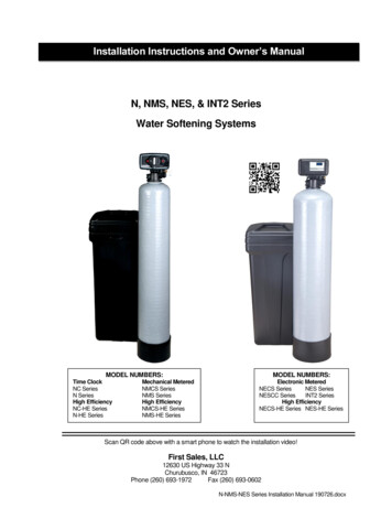
Cautions before installation1. Install a pressure regulator and water hammer arrestor if pressure exceeds maximum rating at any time. Note: Ifdaytime pressure is over 80 psi, night time pressure may exceed maximum pressure rating.2. Do not install on water that is microbiologically unsafe without adequate disinfection before or after the unit. Foreffective disinfection install a Rainfresh Drinking Water System or Rainfresh UV disinfection system.3. For use on cold water only.4. Only use thread seal tape (Teflon tape) for fitting connections into unit. DO NOT USE pipe dope or chemicalsealants.5. If water pipes are used to ground electrical system, install jumper wire (#4 gauge solid copper wire) across the unitto maintain proper grounding of your electrical system6. Protect your unit from freezing - drain the unit if freezing temperatures exist.7. NOTE: IF SOLDER TYPE FITTINGS ARE USED DO NOT USE torch near inlet/outlet connections. All solder jointsshould be made before joining pipe to filter head. Use only lead-free solder and flux.8. DO NOT over-tighten metal fittings on to unit connections.9. You will need softener salt with this unit (not included). Softener salt is sold at most retailers.10. Place the unit on a flat level surface. Do not place shims under the unit to level it. The weight of the unit full ofwater and salt can cause the softener tank to crack at the shim.11. The unit should only be moved by 2 or more people due to heavy weight. Failure to do so can result in back or otherinjury.12. The unit must be installed in an area where there is reasonable access to the salt tank for regular salt filling.D. INSTALLATIONElectrical Requirements: The automatic control valve requires a constant power supply - 110V AC. We recommend a GFI (ground faultinterrupter) outlet within 5 feet of the softener. Extension cords are not recommended. If water pipes are used to ground electrical system, you will need to install a jumper wire across the filter unit.Unpacking the unitThe unit includes:1) Softener tankwith controlvalve and bypassvalve & brine(salt) tank5) Drain hose (15 ft) with hoseclamp2) Inlet/outlet elbow fittings (2)– ¾” Male NPT4) Brine overflow fitting3) Allen key (for ease of opening& closing bypass valve)6) AC power adapterUnpack the unit and place it at the location where you intend to install it. Stand back and look at the softener to make sure it is standing straight up and not tilted to one side. Make sure yourchosen location will be fairly level, dry, and protected from possible freezing conditions. The softener can sit directly onthe floor and will not corrode. DO NOT set the softener onto make shift platforms as this can damage the salt tank, ormay cause it to topple.3
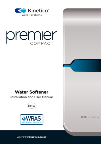
The system has 3 connections - an inlet, an outlet, and a drain line connection. Ifyou are looking at the back of the unit (fig 1), the inlet is on the left side. Warning:Make sure that you have correctly identified the inlet of the system. REVERSINGTHE CONNECTIONS WILL RESULT IN RESIN BEADS BEING THROWN INTO YOURHOME'S PLUMBING SYSTEM CAUSING DAMAGE TO IT AS WELL AS THESOFTENER. The following pipe can be used for installing your new system - Copper, CPVC, andPEX are the most popular.Installation LocationInstallation location for city (municipally treated) waterInstallation location for well water: You may choose not to treat the water spigots that go outside used for irrigation or sprinkler systems. You will have toplan the job so that you cut in to feed the softener AFTER these spigots.4
BEFORE YOU BEGIN INSTALLATION, CONFIRM THE INLET AND OUTLET OFTHE UNIT AND IDENTIFY THE SERVICE AND BYPASS POSITIONS OF THEVALVE. The bypass valve is used to isolate the unit from the plumbing system inorder to perform maintenance or repairs on the unit. During normal use the bypassvalve should be in “SERVICE” position and to isolate it, the valve should be turned to“BYPASS” position (Fig 2).Plumbing in your softener If your hot water tank is electric, turn off the power to it to avoid damage to theelement in the tank. If you have a private well, turn the power off to the pump then shut off themain water shut off valve. If you have municipal water, simply shut offthe main valve. Go to a faucet, (preferably on the lowest floor of thehouse) turn on the cold water until all pressure is relieved and the flow ofwater stops. Position the softener in the desired location. The unit comes with two90 ¾” male NPT elbow connections (see Fig 3). You can turn them at anyangle to suit your installation. Make sure that the bypass valve is inbypass mode as shown in Fig 2. Note: To change the connection fitting, simply remove the locking clipsby hand and pull the fitting out. Insert new fitting and reinstall lockingclip (Fig 2).Fig 2 Plumb in the softener using appropriate fittings. Attach the drain hose (15 ft included) to the drain fitting and secure itwith a hose clamp (Fig 4) (included).Fig 3 Run the drain line to a nearby laundry tub, standing pipe or floor drain(Fig 5) and cut off excess tubing.NOTE ABOUT DRAIN LINE : You can run the drain hose from the unit tothe ceiling joists (max 8 ft ceiling) and run it to the nearest laundry tub ordrain pipe. This can be run up overhead or down along the floor. UseFig 4band clamps to hold the drain tubing in place. If running drain line morethan 15 feet from the softener (max 25 ft), increasing the line size to 3/4" will be required. Please follow your localplumbing & other applicable codes for where to run softener discharge water. NEVER MAKE A DIRECT CONNECTIONINTO A WASTE WATER DRAIN. A PHYSICAL AIR GAP OF AT LEAST 1.5" SHOULD BE USED TO AVOID BACTERIA ANDWASTEWATER TRAVELING BACK THROUGH THE DRAIN LINE INTO THE SOFTENER (see fig 5). If you have other waterconditioners, such as an iron filter, carbon filter, tannin filter etc., RUN THE DRAIN TUBING FOR EACH UNIT SEPARATELY.DO NOT TEE (COMBINE) DRAIN TUBING FROM OTHER UNITS.Min 1.5”air gapMin 1.5”air gapMin 1.5”air gapSTANDING PIPELAUNDRY TUBFig 5You can also use code-approved air-gap attachments available at most plumbing stores.5FLOOR DRAIN OR SUMP
Remove the lid on the salt tank. Insert the brine well into the appropriate slot atthe bottom of the salt tank (Fig 6). Slide the 3/8” tube through the hole on the sideof the salt tank and connect it to the brine float as shown in Fig 7.Remove locking clip on the brine outlet (Fig 8) and insert other end of the 3/8”tube until it goes no further. Replace locking clip. The salt tank is flexible and canbe moved around the softener as long as it is connected to it through the 3/8”brine tube.Attaching the overflow tubing : If the safety overflow is not already attached tothe brine (salt) tank, drill a ¾” hole on the side of the brine tankabout ¾ of the way from the bottom (Fig 9). Insert the over flowfitting from the outside and tighten the nut from the inside tolock it in place.Attach the rest of the drain tubing to the overflow fitting and runto the floor drain with an appropriate air gap, as shown in fig 5. Ifyou do not have any more drain tubing left, you will need topurchase extra tubing at your local plumbing retailer. WARNING :DO NOT TEE THE OVERFLOW TUBING TO THE DRAIN TUBING Add about 5 gallons of water in the salt tank. This is not a criticallevel but just helps with the process for the first regeneration.Then add 2 bags (20 Kg bags) of salt to start with. Turn the main house shut-off valve on slightly and watch forleaks. Make sure a faucet is on somewhere and that any aeratoris removed to avoid clogging from loosened scale in the pipes. Ifyou have no leaks, proceed to the next steps.Fig 6Fig 7Fig 8Turn on the water supply Using the Allen key (included), turn the bypass inlet slightly to allow water torun into the unit. The water should initially fill the tank slowly. Once the tank isfull of water, you can open valve fully. This prevents resin from being pushed upinto the control head by the initial surge of water going in. Make sure there are no leaks in your plumbing before proceeding. At the nearest cold treated water tap remove the faucet screen and open thefaucet. Using the Allen key (included), open the outlet side of the bypass valveand let water run a few minutes or until the system is free of any air or foreignmaterial resulting from the plumbing work. Close the water tap when waterruns clean, and then proceed to start up instructions. Connect the control valve to the power adapter (fig 10) & connect the adapterto the power supply.NOTE: Your unit is not yet ready for service until you complete programming andmanual regeneration. See next page.6Fig 9Fig 10
E. START UP & PROGRAMMINGThe control valve is controlled with simple, user-friendly electronics displayed on an LCD screen.When power is first supplied, the valve electronics may take up to a minute to initialize. During this time the screenmay show “INTIALIZING WAIT PLEASE”. Do not touch any buttons at this time. When the valve reaches the serviceposition, it will display the following information in sequence. THIS IS NORMAL1. Date & Time2. Total & Remaining Gallons3. No. of people in the house & Reserve Capacity4. Estimated days left for next regeneration5. Last Regeneration date6. Total # of regenerations7. Total Treated Gallons of water8. Overrun TotalThe control valve has a display screen and 4 buttons9.10.11.12.13.14.15.16.Current and Peak water flow rateDay overrideRinse overrideDelayed RegenerationRegeneration TimeRefill TimeValve ModelValve IDJUN/21/202005:27 PMSETTINGSThe function of this key is toenter the level oneprogramming mode wherethe valve settings can beadjusted.MANUAL REGENThis button has two functions. The first is to initiatea manual regeneration by holding the button for 3or more seconds. The second function is while inprogramming mode, pressing this key allows theuser to change the value of each setting.UP / DOWNThese buttons are used toincrease or decrease the valueof the settings while in theprogramming mode.PROGRAMMING(I)LANGUAGE SELECTIONJUN/21/202005:27 PMPress SETTINGS for 3 sec.After 3 seconds the display willbeep confirming unlockLANGUAGEENGLISHJUN/21/202005:27 PMPress SETTINGS and REGENbutton together for 3 seconds.The display will beep & changeto LANGUAGEPress SETTINGS again to exitLanguage selection.7LANGUAGEENGLISHPress UP or DOWN key toselect your preferred language
(II)BASIC PROGRAMMINGJUN/21/202005:27 PM1. Press SETTINGS for 3 sec.2. After 3 seconds the displaywill beep confirming unlockTIME OF DAY08 : 27 PMTIME OF DAY05 : 27 PM3. Press SETTINGS again andthe hour value becomeshighlightedTIME OF DAY08 : 51 PM5. Press SETTINGS again.Hour value will beaccepted and minutevalue will be highlighted6. Press UP or DOWN key tochange minute value tocurrent minutesTIME OF DAY08 : 51 AMYEAR20188. Now press UP or DOWNkey to change AM/PMvalue to current timeMONTHJUNTIME OF DAY08 : 27 PM4. Press UP or DOWN key tochange the hour value tocurrent timeTIME OF DAY08 : 51 PM7. Press SETTINGS key againand AM/PM will behighlighted.YEAR20209. Press SETTINGS buttonagain and YEAR will behighlighted10. Now press UP or DOWNkey to change YEAR tocurrent year11. Press SETTINGS again to highlightand use UP or DOWN keys toselect current month. Then pressSETTINGS again to advance toDATEDAY01SET HARDNESS25.0 gpGSET HARDNESS24.0 gpG12. Press UP or DOWN toenter CURRENT DATE.13. Press SETTINGS again toadvance to “SET HARDNESS”14. Press UP or DOWN key toenter your water hardness ingrains per gallon. See note8
NOTE : Setting Water HardnessThis value is the hardness value of your water in grains per gallon (GPG). If you have the reading in PPM or mg/L,simply divide that by 17.1 to get the reading in GPG. You must also add (5 x iron level in PPM) to the hardnessvalue.HARDNESS VALUE YOUR WATER HARDNESS (5 x Iron concentration in PPM)For example, if your water hardness is 20 GPG and the iron level is 0.3 PPM, the hardness value you enter must be20 5 x (0.3) 20 1.5 21.5 GPGNote: If you do not know your water hardness, we highly recommend that you get a water test to confirm this.Until then you can leave the setting at default.SET PEOPLE4SALT SETTINGSTANDARDSET PEOPLE615. Press SETTINGS againadvance to “SET PEOPLE”to16. Now press UP or DOWN keyto enter number of people inyour household.WATER SOURCEWELL/OTHERSALT SETTINGSTANDARD18. Leave at STANDARD (factory setting). If your water isclean and municipally treated, press UP or DOWNkey to change the value to HIGH EFFICIENCYREGEN. TIME02:00 AM20. Press SETTINGS to advanceto “REGEN TIME”. This isthe time when the unit willcompleteregeneration.Leave at default setting oruse UP or DOWN keys tochange per your choice17. Press SETTINGS again toadvance to SALTSETTINGS.19. Press SETTINGS to advance to “WaterSource”. Do not change this setting.LOAD DEFAULTNO21. Press SETTINGS again toadvance to “LOADDEFAULT”. Do not changethis setting unless you wantto change all your settingsto factory settings9PROGRAMMINGCOMPLETE22. Press SETTINGS again andthiscompletestheprogramming
(III)ADVANCED PROGRAMMINGIn the advanced programming, you can change individual regeneration cycle times. DO NOT change thesewithout confirming with Rainfresh technical support. By changing these values your unit can malfunction.VALVE MODEVALVE MODESYSTEM SIZESOFTENER DFSOFTENER DFRESIN VOL.Unlock display by pressingSETTINGS for 3 sec. Press UP& DOWN keys together for 3seconds until unit beeps anddisplay changes to VALVEMODE.Leave VALVE MODE at defaultsetting. Press REGEN button toadvance to “SYSTEM SIZE”.Leave SYSTEM SIZE at defaultsetting (RESIN VOL). PressREGEN button to advance to“RESIN VOL”.RESIN VOL.RESIN VOL.SALT SETTING1.00 CF1.00 CFSTANDARDSet RESIN VOL as follows:ModelModelModelModelPress REGEN button toadvance to “SALT SETTING”30T – 1.00 CF45T – 1.50 CF60T – 2.00 CF90T – 3.00 CFLeave at STANDARD (factorysetting). If your water is cleanand municipally treated, pressUP or DOWN key to changethe value to HIGH EFFICIENCYPress REGEN button toadvance to “BACKWASH”BACKWASHBRINEBRINE5 MINUTES53 MINUTES53 MINUTESDefault BACKWASH is set for 5min. Press UP to increase thissetting if your water has highturbidity or ironPress REGEN button toadvance to “BRINE”10Default brine is set for 53 min.You can use UP arrow key toincrease this setting to max 70min if your water has someiron
REFILLRINSERINSE4 MINUTES4 MINUTESPress REGEN button toadvance to “RINSE”Default RINSE is set for 4 min.You can use UP arrow key toincrease this setting if youprefer a more thorough rinseLOCK VALUELOCK VALUEUNLOCKLOCKPress UP or DOWN key toeither LOCK your settings orleave them unlockedPress REGEN button toadvance to completeprogrammingAUTO 2.5 MINPress REGEN button toadvance to “REFILL”. This is setto AUTO. Press REGEN toadvance to LOCK VALVEPROGRAMMINGCOMPLETEDisplay will briefly showPROGRAMMING COMPLETE & go tohome screen. It will now displayvarious settings in sequence.Disinfecting the SoftenerIt is possible that during shipping, storage & installing, bacteria can go into the unit.Therefore, as a good installation practice, it is recommended that the softener bedisinfected prior to use. To disinfect, open the lid of the brine well in the salt tank and addapprox. 3 tablespoons of fresh common household bleach. Replace lid & proceed tomanual regeneration.Open this lid &pour bleach insideManual RegenerationTo perform a manual regeneration, follow the following steps.JUN/21/202005:27 PMPress SETTINGS for 3 sec.After 3 seconds the display willbeep confirming unlockREGENERATIONIMMEDIATELYPress and hold REGEN buttonand display changes toREGENERATION.YOUR UNIT IS NOW READY FOR SERVICE11ADVANCING TOBACKWASHPress REGEN button again andthe unit will start theregeneration process. This willlast for over an hour.
F. OTHER FEATURESControl operation during a power failureIn the event of a power failure, the valve will keep track of the time and day for 48 hours. The programmedsettings are stored in a non-volatile memory and will not be lost during a power failure. If power fails while theunit is in regeneration, the valve will finish regeneration after power is restored. If the valve misses a scheduledregeneration due to a power failure, it will queue regeneration at the next regeneration time once power isrestored.Safety floatThe brine tank is equipped with a safety float which prevents your brine tank from overfilling as a result of amalfunction such as a power failure.New soundsYou may notice new sounds as your water softener operates. The regeneration cycle lasts approximately 2 hours.During this time, you may hear water running intermittently to the drain.Manual bypassIn the case of emergency, such as an overflowing brine tank, you can isolate your water softener from the watersupply using the bypass valve located at the back of the control. To resume soft water service, open bypass valveby rotating the knobs counterclockwise.G. MAINTENANCEAdding SaltFill the salt tank only with nugget or pellet salt that is specifically for water softeners only. DO NOT USE rock salt,road salt or other types of impure salts. Use only high grade water softener salt (Sodium Chloride). You can usePotassium Chloride but you will need to increase salt settings. Check the salt level monthly. It is important toALWAYS maintain the salt level above the water level. To add salt, simply slide open the salt tank lid and add thesalt directly into the brine tank. Be sure the brine well cover is on and fill only to the height of the brine well. The salttank should never be empty.WARNING : DO NOT OVERFILL THE SALT TANK TO THE TOP. Once you can see the waterlevel in the tank, do not fill more than 2-3 bags of salt.YOU WILL NOT BE ABLE TO SEE THE WATER ONCE YOU ADD A COUPLE OF BAGS OF SALT. IF YOUWANT TO CHECK THE WATER LEVEL, OPEN THE LID ON THE BRINE WELL.Preventing and breaking a Salt BridgeHumidity or wrong type of salt may create a cavity between the water and the salt. This action,known as “bridging”, prevents the brine solution from being made, leading to your watersupply being hard. If you suspect salt bridging, pour some warm water over the salt to break upthe bridge. Allow four hours to produce a brine solution, and then manually regenerate thesoftener. This should always be followed up by allowing the unit to use up any remaining saltand then thoroughly cleaning out the brine tank.If you are unable to break the bridge this way, take a strong rod and carefully push down thesalt, working it up and down. Do not pound on the walls of the tank. If the wrong kind of salthas been used, take it out and fill with nugget or pellet salt.12
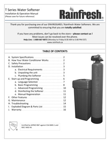
Care of Your SoftenerTo retain the attractive appearance of your new water softener, clean occasionally with mild soap solution. Do notuse abrasive cleaners, ammonia or solvents.Cleaning the Injector AssemblySediment, salt and silt will restrict or clog the injector. A clean water supply and pure salt will prevent this fromhappening. The injector assembly is located on the right side of the control valve. This assembly is easy to clean.Shut off the water supply to your softener and reduce the pressure by opening a cold soft water faucet. Using ascrewdriver, remove the two screws holding the injector cover to the control valve body. Carefully remove theassembly and disassemble as shown in Figure 6. The injector orifice is removed from the valve body by carefullyturning it out with a large screwdriver. Remove the injector throat the same way. Carefully flush all parts includingthe screen. Use a mild acid such as vinegar to clean the small holes in the orifice and throat.Reassemble using the reverse procedure.InjectorScreen13
H. TROUBLESHOOTINGPlease review the following troubleshooting guide before calling customer service. If you are unable to resolve the problem using the guide below, please call customer service at1800 667 8072 (Mon to Fri 8:30 AM to 5 PM EST) Please have your receipt & model number ready before you call. Customer service may requestdigital pictures of your installation in order to help troubleshoot the unit.ISSUEA. Unit fails to start aregeneration cyclePOSSIBLE CAUSE1. No power supply2. Defective circuit board3. Defective motor4. Defective meterB. Water is hard1.2.3.4.5.C. Salt use is high1. Salt setting highD. Low water pressureE. Resin in drain lineF. Too much water in brinetankG. Unit fails to draw brineH. Unit cycles continuouslyI. Water flows to draincontinuouslyJ. Softener is leakingbetween the bypassvalve and control valveK. Softener is alwaysflashing throughdifferent pieces ofinformationM. My display screen isblankBypass valve is closedNo salt in salt tankPlugged injector/screenLeak between valve and riser tubeInternal valve leak1. Iron or scale buildup in line feedingsoftener2. Iron buildup inside valve or tank3. Inlet of control valve plugged dueto dirt1. Air in water system2. Incorrect or missing drain line flowcontrol (DLFC)3. Unit sucking air during brine draw1. Plugged injector or screen2. Plugged brine valve3. DLFC plugged1. DLFC plugged2. Injector or screen is plugged3. Inlet pressure too low4. Internal valve leak1. Defective circuit board1. Valve settings incorrect2. Internal leak1. Possible O-ring leakPOSSIBLE SOLUTION1. Check electrical service & re-set time of day2. Replace faulty parts3. Replace motor4. Replace meter1. Open bypass valve2. Add salt to salt tank3. Clean parts (see page 11)4. Check if riser is cracked or O-ring is damaged.Replace faulty parts5. Replace valve seals, spacer and piston assembly1. Under ADVANCED PROGRAMMING change saltsetting to high efficiency (not recommended forwater with iron)1. Clean/replace supply line2. Clean control valve & add resin cleaner to cleanbed. Increase regeneration frequency3. Clean control valve inlet1. Check well system for proper air elimination2. Check and replace DLFC3. Check and secure all connections from valve tobrine safety float1. Clean parts (page 9)2. Clean parts3. Clean DLFC1. Clean DLFC2. Clean parts3. Increase min pressure to at least 25 psi4. Replace seals, spacer & piston assembly1. Replace faulty parts1. Check valve settings2. Replace seals, spacer & piston assemblyCheck the metal adapter clips holding the 2components together and tighten if necessary.Replace O-rings as requiredThis is normalNo action required1. Power cord may be unplugged fromeither adapter or receptacle2. Defective circuit board1. Re-connect power cord2. Call Rainfresh to receive new circuit board withreplacement instructionsNeed help troubleshooting? Call Toll Free 1-800-667-8072 Monday to Friday 8:30 AM to 5 PM EST.14
I. PARTS LIST15
DESCRIPTIONJ. WARRANTYThis “T” Series Softener System is warranted to the original Consumer purchaserfor a period of one (1) year, from the date of purchase, against defects in materialsor workmanship. The electronic controls and mineral tank are warranted for 5 and10 years respectively against defects in materials or workmanship. The company'sobligation under this warranty shall consist of repair or replacement, at its option,of any part found by company inspection to be defective, provided that theproduct has not been misused, abuse, altered or damaged by Consumer withrespect to the original installation, as determined by the company. This warrantywill not apply if water passing through the System has a) Turbidity / SuspendedSolids 5 ppm (mg/l). b) Hydrogen Sulphide concentrations greater than 0.05 ppm(0.05 mg/l). c) Iron concentration greater than 0.3 ppm (0.3 mg/l), d) Manganesegreater than 0.05 ppm (0.05 mg/l),e) Tannins or colour or other feed waterconditions that exceed the water quality requirements of the softener. This limitedWarranty applies only to a unit when returned to the Warrantor at the owner’sexpense and in accordance with shipping instructions received from the Warrantor.This warranty does NOT cover, a
You will need softener salt with this unit (not included). Softener salt is sold at most retailers. 10. Place the unit on a flat level surface. Do not place shims under the unit to level it. The weight of the unit full of water and salt can cause the softener tank to crack at the shim. 11.