Transcription
INSTALLATION MANUALWATER SOFTENER SYSTEMSFLEET FARM WATER SOFTENERFLEET FARM WATER TREATMENT, 1900 PROSPECT CT.APPLETON WI 54914, 1.800.777.1426PH 920.739.9406 FAX
Table of ContentsIMPORTANT SAFETY INFORMATION – READ ALL . 3INSTRUCTIONS BEFORE USING . 3SOFTENER ANATOMY . ERROR! BOOKMARK NOT DEFINED.SPECIFICATIONS . 4FEEDWATER . 4POWER . 4INSTALLATION . 4SALT CAPACITY . 4SETUP. 4UNPACKING and INSPECTION . 5W HERE TO INSTALL THE SOFTENER . 5HARDNESS SETTING . 5INSTALLATION . 5CONTROL START-UP PROCEDURES . 9SOFTENER OPERATION . 101. BRINE DRAW / SLOW RINSE POSITION . 112. BACKWASH POSITION . 113. FAST RINSE POSITION . 114. BRINE FILL. 115. SERVICE . 11SERVICE . 12CLEANING IRON OUT OF THE W ATER SOFTENING SYSTEM . 14CHECKING FOR A SALT BRIDGE . 14BREAKING A SALT BRIDGE. 14CLEANING THE INJECTOR AND SCREEN . 14TROUBLESHOOTING . 15WATER SOFTENER SYSTEM PARTS LIST . ERROR! BOOKMARK NOT DEFINED.ERROR! BOOKMARK NOT DEFINED.
Important Safety Information – Read AllCAUTION: Read and follow the information in this manual tominimize the risk of electric shock or personal injury.!IMPORTANT! If you are unsure about installing your FleetFarm Water Treatment water softener, contact the Fleet FarmWater Treatment helpline or consult a professional plumber.IMPORTANT! This system must be installed in compliancewith applicable state and local codes, law, and regulations.Instructions Before Using Before beginning installation, read these instructions completely. Then obtain all the materials andtools needed for installation.NOTE: Failure to install the Fleet Farm Water Treatment system correctly voids thewarranty.Perform installation according to state and local plumbing codes.Use only lead-free solder and flux for sweat-solder connections, as required by state andfederal codes.Handle all components of the Fleet Farm Water Treatment system with care. Do not drop, drag orturn components upside down.Be sure the floor under the water softening system is clean and level.The Fleet Farm Water Treatment system uses 110volt 60 Hz electrical power.Plug transformer into an indoor 120 volt, grounded outlet.Properly ground Fleet Farm Water Treatment system to conform with all codes andordinances.Install Fleet Farm Water Treatment system in a protected area. Be sure electric outlet andtransformer do not come in contact with water. See Where to Install the Softener, in the installationsection of the manual.Do not attempt to treat water over 110 F with the Fleet Farm Water Treatment system.Always connect the Fleet Farm Water Treatment system to the main water supply pipebefore water heater.Do not expose Fleet Farm Water Treatment system to freezing temperatures. Water freezingin the system causes equipment damage.Do not install in direct sunlight. Heat from sun may cause damage.Minimum inlet water pressure is 20 psi. Maximum inlet water pressure is 125 psi. Use pressurereducing valve if necessary.Use clean water softening salts only, at least 99.5% pure. Failure to use the correct salt may create ahealth hazard or maintenance problems.Use nugget, pellet, block, solar, or coarse solar salts.Do not use granulated or ice cream making salts.Always keep the salt lid in place unless servicing the unit or replenishing salt.CAUTION:! Do not use with water that is unsafe or of unknown quality.Test water periodically to verify that the system isperforming satisfactorily.Discard small parts remaining after the installation.
SpecificationsFeedwater! Do not use this system on water that is microbiologically unsafe or of unknown quality without adequatedisinfection before or after the system. !Minimum inlet pressure: 20 psigMaximum outlet pressure: 125 psigMinimum water temperature: 34 degrees FMaximum water temperature: 110 degrees FPowerVoltage: 120VACFrequency: 60HzPower consumption: 3 Watts MaximumInstallationLocation: Indoors (Protect from direct sunlight)Minimum ambient temperature: 34 degrees FMaximum ambient temperature: 122 degrees FSalt CapacityAll Models 300 lbs (181 MFFC-835-MRed(resin)Red(fine resin)Red(resin)Minimum SaltingMedium SaltingMaximum SaltingFlow Rate vs Pressure 26,7009.32.933,40015.92.17 1.04.05.524,6006.14.026,8009.32.933,40015.92.17 5.03.25.29,7003.23.113,8006.12.319,8009.32.17 515.02.09.014.41.5Media TankBrine TankTotal ABCDEFFF-948-M94818335627FFE-1054105418336128Total Dimensions: 14" W x 21" D x 44" HFFC-835-MModelNumberWater TestWater test can be obtained at Fleet Farm in the plumbing department, water treatment professional or locallaboratory. This information will be need to set up the control valve properly. Please record below.HardnessIronpHGPG (Grains per Gallon)PPM (Parts per Million)
SetupUnpacking and InspectionCheck the Fleet Farm Water Treatment system components for damage or missing parts.Where to Install the SoftenerConsider the following points when determining where to install the water softener: Place the Fleet Farm Water Treatment system as close as possible to a sewer drain. Do not install the softener where it would block access to the water heater, or access to the main water shutoff,water meter, or electrical panels. Keep outside faucets on hard water to save soft water and salt. Install the softener in a place where water damage is least likely to occur if a leak develops. A 120V electrical outlet is needed to plug in the transformer. If the outlet is remote (up to 100 feet), use 18 gaugewire to connect. Always connect the Fleet Farm Water Treatment system to the main water supply pipe before the water heater. If using well water, always install the Fleet Farm Water Treatment system after the pressure tank, but before thewater heater. Install the Fleet Farm Water Treatment system where it will not be subject to temperatures outside of the limitsstated in the Specification section or to direct sunlight.Hardness SettingMunicipal WaterFleet Farm recommends that you bring in a sample of water in to be tested. Fleet Farm personnel will test your waterfree of charge. Or call your local water company to determine your water hardness in grains per gallon and iron inmg/l (or ppm).Well WaterAgain, Fleet Farm recommends you bring a sample to the store to be tested or have your water tested professionallyfor accurate hardness and iron content.Installation1. Turn off gas or electric supply to the water heater.2. Turn off the water supply to pipes to be cut and drain the house water pipes.3. Open both hot and cold faucets.4. Move the softener assembly into installation position. Be sure the installation surface is level and smooth. Provisions should be made to by pass outside faucets.5. Plumb IN and OUT connections to and from softener.
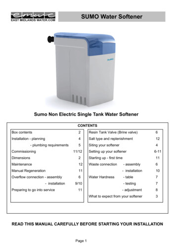
Be sure the incoming hard water supply is directed to the INLET port of the valve.The valve body of the control is marked with arrows indicating the proper flow direction.Connections are illustrated below.OutletInletFigure 2CAUTION: If making a soldered copper installation, do all sweat soldering before connecting pipes to the bypass valve.Torch heat will damage plastic parts.CAUTION: When turning threaded pipe fittings onto plastic fittings, use care not to cross-thread.CAUTION: Use Teflon tape on all external pipe threads. Do not use pipe joint compound.CAUTION: Support inlet and outlet plumbing in some manner (use pipe hangers) to keep the weight off of the valvefittings.Perform steps 6-9 to install flexible drain hose.Skip to step 10 to install rigid drain pipe.6. Find barbed fitting. (Fig 4, A). Attach barbed hose fitting to the 1/2" male NPT drain outlet (not supplied withwater softener).7. Cut the length of the hose in half. One section will be used as a valve drain hose. The remaining section will beused as an overflow hose in Step 11.8. Connect and route the valve drain hose. To keep water pressure from blowing the hose off, use a hose clamp to secure.9. Locate the other end of the hose at a suitable drain. Tie or wire the hose in place at the drain point. Provide an air gap of at least 1-1/2" between the end of thehose and the drain point.
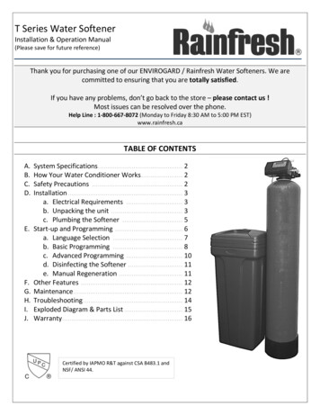
Figure 3A – Hose barb from valveB – Overflow hose off of brine tankC – Valve drain hoseUse Step 10 to install rigid drain pipe.10. To adapt a rigid drain pipe to the Fleet Farm Water Treatment system, unscrew the attached barbed hose fitting tovalve. Instead, plumb rigid tubing directly to the 1/2" male NPT drain fitting.ABA - 1/2” female NPT drain outletB - Rigid drain pipeFigure 411. Take the other half of the cut hose and attach it to the overflow adapter elbow located on the side of the brinetank. Use a hose clamp to hold it in place. Locate the other end of the hose at the drain point as shown in Figure3.12. Fully open two (2) cold (soft) water faucets near the water softener.
13. Place bypass valve in "bypass" position.Figure 514. Fully open the house main water shutoff valve. Observe a steady flow from both faucets opened earlier.15. Slowly, turn bypass valve back in the "service" position. Keep soft water faucets open.16. After about 3 minutes, open a HOT water faucet for one (1) minute, or until all air is expelled, then close.NOTE: If water appears cloudy or has salty taste, allow to run for several more minutes, or until clear.17. Close all water faucets.18. Check plumbing work for leaks and fix immediately if any are found.19. Remove the cover and add water into the tank. Although the material used in the manufacturing of this watersoftener will not contaminate your water supply, the softener could become contaminated during shipment andinstallation. The media inside the resin tank may also have become disturbed during shipping. The followingprocedure will help re-position the media, sanitize, flush and condition your water softener:a) Add 1-1/2 ounces of common household bleach to the water in the cabinet (brine tank).b) Following the directions in the Control Service Manual, manually advance the softener through each step ofregeneration pausing for 10 minutes in each cycle except the Fill cycle (see step c.).c) Repeat step 19a and 19c after any service has been performed on your water softener.20. Turn ON the gas or electric supply to the water heater.21. Remove the cabinet cover and add salt into the tank. Use only nugget, pellet, block or coarse solar salt with apurity of 99.5% or higher. DO NOT use rock, granulated, and ice cream-making salts. Keep the brine tank coveron unless servicing or refilling with salt.22. Connect electrical power by plugging into a (120 volt) outlet.23. With the valve In Service, manually initiate regeneration as the final installation step. This regeneration will:a) Fill the brine tank with the appropriate amount of water for the 1st regenerationb) Complete the final flushing and conditioning of the water softener.c) Re-classify the resin bed if the bed was disturbed during shipping.
Control Start-up ProceduresModelsFF-844M, FF-844EM, FF-844TFF-948M, FF-948EM, FF-948TFFE-1054M, FF-1054EM, FF-1054TFFC-835M, FFC-835EM, FFC-835TFor replacement copies of these manual please contact Fleet Farm.ProgrammingSetting time of day for all unitsSet time of day: Press RED TIME SET BUTTON and turn 24 HOUR GEAR until present time of day is aligned withTIME OF DAY arrow. Figure 5Figure 5Figure 6Programming metered softener controlNote: Hardness and iron can be found on Page 3.Note: The manufacturer's predetermined salt setting is the most effective setting for your particular model. Allsofteners are set for a medium capacity salt setting which can be found under CAPACITY & PERFORMANCESPECIFICATIONS on Page 2.Check Salt Setting: Check the label on the back timer cover for the salt setting. Remove back cover and make surethe setting is correct. The salt cam is on the left hand side of the control. See flow diagram 8.To program water softener: First you must know the hardness and iron content of your water. Set regenerationprogram by lifting (pulling) and rotating the PEOPLE DIAL so the number of people in the household is aligned withthe "compensated" GRAINS PER GALLON of hardness (hardness dial) of your water.Grains per Gallon of Hardness (4 x Iron ppm) Compensated hardness
Example:Hardness 21 gpg and iron 1 ppm21 (4 x 1) 25 gpg compensated hardnessRelease the dial and check for firm engagement of the gear teeth. See control valve diagram (Figure 5). The unit isset for a household of three people with a hardness of 10 grains per gallon. By doing this you have also just set thenumber of gallons between regenerations. Notice the white dot on the program wheel. This dot is adjacent to anumber on the GALLON DIAL which is the amount of water available when fully regenerated. The control in Figure 5.indicates that it is set for 850 gallons.Notice the black arrow which always points to the number of gallons remaining until the next regeneration. In Figure5. the program wheel reads 0 (zero) gallons, indicating that there are no gallons remaining and that the unit willregenerate at the next 2:00 A.M. When the dial reaches zero there is a reserve capacity left equaling 75 gallons foreach person in the household.Programming time clock softener controlSet the softener to regenerate every 2 days (the factory setting) as a starting point See Figure 6. See care and useInstructions. Set the days that regeneration is to occur by sliding the desired TABS on the SKIPPER WHEELoutward away from the center of the WHEEL to expose TRIP FINGERS. Each TAB is one day. Be sure that theTABS for days that regeneration is not desired are pushed in fully toward the center of the WHEEL. The REDPOINTER represents the upcoming 2:00 a.m. Moving clockwise from the RED POINTER, pull-out or push-in TABSto obtain the desired regeneration schedule.Water softener start-upNOTE: The various regeneration positions may be set manually by turning the MANUAL REGENERATION KNOB onthe front of the control in a clockwise direction until the POSITION INDICATOR shows the desired position. SeeFigure 5.1. Manually index the control into the SERVICE position and allow the tank to fill with water. When the flow stops,open a treated water tap until all air is released from the lines. Close the tap.2. Manually index the control to the BACKWASH position and allow water to flow at the drain for 3 or 4 minutes oruntil free of air bubbles.3. Manually index the control to the Refill position and allow brine tank to fill with approximately 8" or 8 gallons ofwater. Or, if desired, pour the same amount in manually.4. Plug electrical cord into permanent 110 volt electrical socket which is not controlled by a wall switch.(Note: See proper operating conditions page 2.5. SALT: Fill brine tank with salt. We recommend 50# salt blocks made for softeners, rock salt, solar salt, or pelletsalt. Add 3 blocks to tank by 'stacking" the blocks on top of each other.NOTE: It is recommended that the brine tank be cleaned once a year, because of the accumulation of silt and sandfrom the salt.6. Make sure that any bypass valving is left in the normal service position.7. Be sure that you have set water usage program wheel for metered controls or set skipper wheel for time clockcontrols.When using the FFE Series softeners on a known iron condition, rust removing salts such as AKZONOBEL'S "RUST STOP TABS" are recommended.Under heavy iron conditions chemical cleaning may be required. Products such as "Iron Out" may be usedfor this purpose. Caution: Follow directions carefully as these products may be dangerous if not properlyused.
Softener OperationAs water enters the softener, it passes over a resin bed in a special tank. The resin consists of tiny beads of a plasticcalled styrene. These beads attract and hold sodium ions and exchange the sodium for hardness ions whenencountered. Over time, the resin becomes saturated with hardness ions and no longer removes hardness materials.The softener goes into a "regeneration" to flush hardness materials to the drain and refresh the resin with sodium.Regeneration is typically programmed to take place in the middle of the night when little or no water is in use.Regeneration consists of four cycles:1. ServiceWhen the softener is In Service it is flowing water through the system and removing hardness minerals from yourwater.2. Backwash PositionBackwash is a rapid upward flow of water that loosens the resin bed and flushes iron particles, dirt and sedimentsfiltered in the bed out to the drain.3. Brine Draw / Slow Rinse PositionBrine Draw is the process in which brine is drawn out of the brine cabinet and passed through the resin in adownward direction. This rinses the resin and large amounts of sodium ions replace the hardness ions accumulatedduring service. Slow Rinse. After brine is completely removed from the brine cabinet into the resin tank the brinevalve closes. Water replaces any remaining brine from the resin, flushing hardness ions removed from the resin todrain.4. Fast Rinse PositionFast Rinse is a fast flow of water down through the resin tank that follows a Backwash. This flushes all remainingbrine from the tank and packs the resin bed for softening efficiency.5. Brine FillBrine is water saturated with large amounts of a salt (sodium chloride). During brine fill, water flows into the saltstorage area after each regeneration and dissolves salt. During the regeneration process, hardness ions on the resinbeads are replaced or exchanged for sodium ions from the brine solution.Softener Anatomy1 Valve2 Bypass3 Resin Tank4 Distributor5 Resin6 Salt Tank
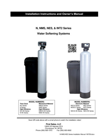
flow diagrams12 Pre RinseService position5 minutes-- Hard water enters the unit at the valve inlet - flows aroundthe lower piston groove - down thru the top of tank passage downward thru the resin - up the distributor tube - thru thecenter hole in the piston - over the top edge of the piston andout the drain line.Hard water enters the unit at the valve inlet - flowsaround the lower piston groove - thru the passage to thetop of tank - down thru the resin and enters thedistributor as conditioned water. The conditioned waterflows up thru the center tube to the valve outlet.3 Backwash10 minutes4 Brine Draw15-20 of 50 minute cycleVAP& DIlIVJ:.ASSDiILyVALVE Ol'V' AS50EMllINJECT-.BY""" Hard water enters the unit at the valve inlet - flowsaround the lower piston groove and lower piston land down thru the center tube and out the distributor - upthru the resin - thru the top of tank passage - around theupper piston groove and out the drain line.Hard water enters the unit at the valve inlet - flows aroundthe lower piston groove - thru the injector nozzle and orificeto draw brine from the brine tank. The brine flows down thruthe resin - into the distributor - up thru the center tube - thruthe center hole in the piston and out the drain line.-11-
flow diagrams5 Slow rinse6 Rapid rinsebalance of 50 minute cycleHard water enters the unit at the valve inlet - flowsaround the lower piston groove and lower piston land down thru the center tube and out the distributor - upthru the resin - thru the top of tank passage - aroundthe upper piston groove and out the drain line.After all the brine has been drawn from the brinetank, hard water continues to enter thru the valveinlet - flows around the lower piston groove - thruthe nozzle and orifice - down thru the resin and intothe distributor - up thru the center tube - thru thecenter hole in the piston and out the drain line.7 Settling rinse5 minutes10 minutes8 Regenerant tank refillAdjustable4-24minutesREFILL (SALT DOSE)ADJUSMENT CAMYAl'lf OlivE ASSEMI(VALVE 04UVIE MSlMIL INE VAlVEflOW CONTICM.tNJlCTOltIItNf TAMIlSAlT LEY(ItUINLlVll'Hard water enters the unit at the valve inlet - flowsaround the lower piston groove - down thru the topof tank passage - downward thru the resin - up thedistributor tube - thru the center hole in the piston over the top edge of the piston and out the drainline.--
ServiceCleaning Iron Out of the Water Softening SystemThe Fleet Farm Water Treatment system is designed to remove minerals like calcium and magnesium fromhousehold water. Fleet Farm Water Treatment recommends periodic resin bed cleaning if your iron rating is high.Clean the bed at least every six months, or more if iron appears in the soft water between cleanings.Checking for a Salt BridgeA hard crust or "Salt Bridge" can form in the lower half of the salt storage tank. This can be deceiving because thetank will appear to have plenty of salt, but underneath, salt has hardened and when the system regenerates, watercannot quite reach this level to be made into brine (water and salt).Breaking a Salt BridgeTake a wooden broom handle and carefully push it down into the salt, working it up and down. If the tool strikes ahard object (be sure it's not the bottom or sides of the tank), it's probably a salt bridge. Carefully break the bridge withthe broom handle. Do not pound on the walls of the tank.NOTE: Salt bridges are typically caused by high humidity or using the wrong kind of salt. In humid areas it is best tofill with less salt, more often. Use only nugget, pellet, block, or coarse solar salt with a purity of 99.5% or higher. DONOT granulated, and ice cream-making salts, or salt with iron-removing additives.Cleaning the Injector and rn off water supply to conditioner:a) If the conditioner installation has a “three valve” by-pass system, first open the valve in the bypass line, and thenclose the valves at the conditioner inlet and outlet.b) If the conditioner has an integral by-pass valve, put it in the by-pass position.c) If there is only a shut-off valve near the conditioner inlet, close it.Relieve water pressure in the conditioner by stepping the control into the backwash position momentarily. Return thecontrol to the service position.Unplug electrical cord from outlet.Disconnect brine tube and drain line connections at the injector body.Remove the two injector body mounting screws. The injector and brine module can now be removed from the controlvalve. Clean and reassemble.To replace brine valve.a) Pull brine valve from injector body, also remove and discard O-ring at bottom of brine valve hole.b) Apply silicone lubricant to new O-ring and reinstall at bottom of brine valve hole.c) Apply silicone lubricant to O-ring on new valve assembly and press into brine valve hole, shoulder on bushingshould be flush with injector body.To replace injectors and screen.a) Remove injector cap and screen, discard O-ring. Unscrew injector nozzle and throat.b) Screw in new injector throat and nozzle, be sure they are sealed tightly. Install a new screen.c) Apply silicone lubricant to new O-ring and install around oval extension on injector cap.Apply silicone lubricant to three new O-rings and install over three bosses on injector body.Insert screws with washers thru injector cap and injector. Place this assembly thru hole in timer housing and intomating holes in the valve body.Tighten screws.Reconnect brine tube and drain line.Return by-pass or inlet valving to normal service position. Water pressure should now be applied to the conditioner,and any by-pass line shut off.Check for leaks at all seal areas. Check drain seal with the control in the backwash position.Plug electrical cord into outlet.Set time of day and cycle the control valve manually toHard water enters the unit at the valve inlet -flows aroundassure proper function. Make sure control valve isthe lower piston groove - thru the injector throat - thru thereturned to the service position.brine valve and flow control to fill the brine tank. HardMake sure there is enough salt in the brine tank.Start regeneration cycle manually if water is hard.water also flows around the lower piston groove - thruthe passage to the top of tank - down thru the resin andenters the distributor as conditioned water. Theconditioned water flows up thru the center tube to the-12- valve outlet.
Troubleshooting1. Softener Fails To Regenerate.A. Electrical service to unit has beeninterrupted.B. Timer programming bad (improperprogramming).A. Assure permanent electrical service (check fuse,plug, pull chain or switch).B. Check programming and reset as needed.2. Softener Delivers Hard Water.A. By-pass valve is open.B. No salt in brine tank.A. Close by-pass valve.B. Add salt to brine tank and maintain salt levelabove water level.C. Clean or replace injectors and screen.D. Check brine tank fill time and clean brine lineflow if plugged.E. Repeated flushings of the hot water tank isrequired.F. Check flow indicator light for flow. Removeobstruction from flow meter.G. Check meter cable connection to timer andmeter.H. Reprogram the control to the properregeneration type, inlet water hardness, capacity orflow meter size.I. Remove and clean any sediment from brine tankand brine valve assembly.C. Injectors or screen plugged.D. Insufficient water flowing into brinetank.E. Hot water tank hardness.F. Flow meter jammed.G. Flow meter cable disconnected ornot plugged into meter.H. Improper programming.I. Plugged brine line or air check.J. Refer to Breaking a Salt Bridge section inmanual.K. No water in brine tank.K. Ensure safety float is not stuck.L. Unit is plumbed backwards.L. Check that the unit is plumbed correctly.M. Water hardness has increased or is M. Retest hardness and change settingsset incorrectly.J. Salt bridge has formed.N. Water pressure is too low.N. Line pressure must be at least 20psi.3. Unit Uses Too Much Salt.A. Improper salt setting.B. Excessive water in brine tank.C. Improper programming.A. Check salt usage and salt setting.B. See problem No. 7.C. Check programming and reset as needed.4. Loss of Water Pressure.A. Iron buildup in line to waterconditioner.B. Iron buildup in water conditioner.A. Clean line to water conditioner.A. Air in water system.A. Assure that well system has proper air eliminatorcontrol and check for dry well condition.B. Ensure drain line flow control is sized correctly.5. Loss of Resin Through DrainLine.B. Drain line flow control is too large.6. Iron in Conditioned Water.A. Fouled resin bed.B. Clean control and add resin cleaner to resin bed.Increase frequency of regeneration.A. Check backwash, brine draw and brine tank fill.Increase frequency of regeneration. Increasebackwash time.B. Iron content exceeds recommend
INSTALLATION MANUAL . WATER SOFTENER SYSTEMS FLEET FARM WATER SOFTENER . FLEET FARM WATER TREATMENT, 1900 PROSPECT CT. APPLETON WI 54914, 1.800.777.1426PH 920.739.9406 FAX . flush and condition your water softener: a) Add 1-1/2 ounces of common household bleach to the water in the cabinet (brine tank).