Transcription
CLICK ANYWHERE on THIS PAGE to RETURN to WATER SOFTENER MANUALS at InspectApedia.comCareSoft Pro Series Metered Water SoftenersFor Models: CSP-844 CSP-948 CSP-1044 CSP-1054 CSP-1248 CSP-1354For Cabinet Models: CSPC-835 CSPC-935 CSPC-1035
TABLE OF CONTENTSPreinstallation Instructions for Dealers . . . . . . . . . . . . . . . . . . . . . . . . . . . .3Bypass Valve . . . . . . . . . . . . . . . . . . . . . . . . . . . . . . . . . . . . . . . . . . . . . . . .3-4Installation . . . . . . . . . . . . . . . . . . . . . . . . . . . . . . . . . . . . . . . . . . . . . . . . . . .7Programming Procedures . . . . . . . . . . . . . . . . . . . . . . . . . . . . . . . . . . . . . .8-9Operating Displays and Instructions . . . . . . . . . . . . . . . . . . . . . . . . . . . .9-11Start-up Instructions . . . . . . . . . . . . . . . . . . . . . . . . . . . . . . . . . . . . . . . .12-13Troubleshooting Guide . . . . . . . . . . . . . . . . . . . . . . . . . . . . . . . . . . . . . .14-15Replacement Parts . . . . . . . . . . . . . . . . . . . . . . . . . . . . . . . . . . . . . . . . . .16-25Specifications . . . . . . . . . . . . . . . . . . . . . . . . . . . . . . . . . . . . . . . . . . . . . . . .26Warranty . . . . . . . . . . . . . . . . . . . . . . . . . . . . . . . . . . . . . . . . . . . . . . . . . . . .27Quick Reference Guide . . . . . . . . . . . . . . . . . . . . . . . . . . . . . . . . . . . . . . . .28YOUR WATER TESTHardnessIronpH*NitratesManganeseSulphurTotal Dissolved Solidsgpgppmnumberppmppmyes/no*Over 10 ppm may be harmful for human consumption. Waterconditioners do not remove nitrates or coliform bacteria, thisrequires specialized equipment.Your CareSoft Pro Series water conditioners are precision built, high quality products. These units will deliverconditioned water for many years to come, when installed and operated properly. Please study this manual carefullyand understand the cautions and notes before installing. This manual should be kept for future reference. If you haveany questions regarding your water conditioner, contact your local dealer or WaterCare at the following:WaterCare1900 Prospect Court Appleton, WI 54914Phone: 920-682-6823 Fax: 920-682-7673
PREINSTALLATION INSTRUCTIONS FOR DEALERS:The manufacturer has preset the water treatment unit’s sequence of cycles, cycle times, salt dose,exchange capacity and salt dose refill time.The dealer should read this page and guide the installer regarding hardness, day override,and time of regeneration, before installation.For the installer, the following must be used: Program Installer Settings: Hardness, Day Override (preset to 12 days), and Time ofRegeneration (preset to 2 a.m., with brine tank refill to occur four hours prior; seeOperating Displays and Instructions for more details) Read Normal Operating Displays Set Time of Day Read Power Loss & Error Display Be sure system and installation are in compliance with all state and local laws and regulations.For the homeowner, please read operating displays and instructions.WATER SOFTENERS:During operation, the normal user displays are time of day or gallons remaining before regenerationwill occur.Days remaining is an optional display but is not normally used. Each of these can be viewed by pressingNEXT to scroll through them. When stepping through any displays or programming, if no buttons arepressed within 5 minutes, the display returns to a normal user display. Any changes made prior to the5 minute time out are incorporated.To quickly exit any Programming, Installer Settings, etc., press CLOCK. Any changes made prior tothe exit are incorporated. If desired, two regenerations within 24 hours are possible with a return tothe preset program. To do a double regeneration:1. Press the REGEN button once. “REGEN TODAY” will flash on the display.2. Press and hold the REGEN button for five seconds until a regeneration begins.Once the valve has completed the immediate regeneration, the valve will regenerate one more timeat the preset.BYPASS VALVE:The bypass valve is typically used to isolate the control valve from the plumbing system’s water pressurein order to perform control valve repairs or maintenance. The 1" full flow bypass valve incorporates fourpositions, including a diagnostic position that allows a service technician to have pressure to test a systemwhile providing untreated bypass water to the building. Be sure to install bypass valve onto main controlvalve, before beginning plumbing. Or, make provisions in the plumbing system for a bypass. The bypassbody and rotors are glass-filled Noryl and the nuts and caps are glass-filled polypropylene. All seals areself-lubricating EPDM to help prevent valve seizing after long periods of non-use. Internal “O” Rings caneasily be replaced if service is required.The bypass consists of two interchangeable plug valves that are operated independently by red arrowshaped handles. The handles identify the direction of flow. The plug valves enable the bypass valve tooperate in four positions.3
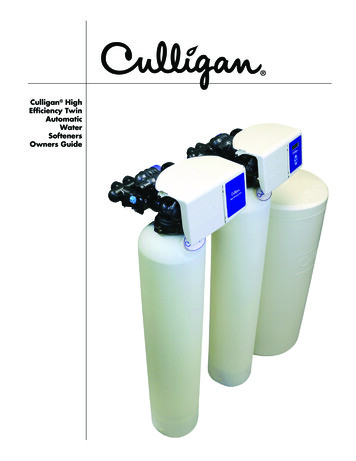
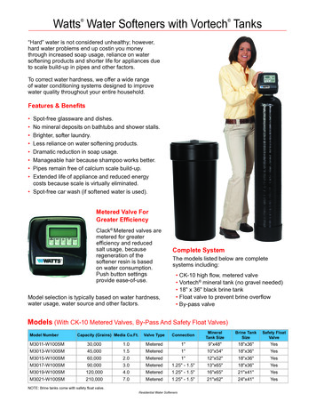
1. NORMAL OPERATION POSITION: The inlet and outlet handles point in the direction of flowindicated by the engraved arrows on the control valve. Water flows through the control valve for normaloperation of a water softener. During the regeneration cycle this position provides regeneration water tothe unit, while also providing untreated water to the distribution system (Fig. 1).2. BYPASS POSITION: The inlet and outlet handles point to the center of the bypass. The system isisolated from the water pressure in the plumbing system. Untreated water is supplied to the building(Fig. 2).3. DIAGNOSTIC POSITION: The inlet handle points toward the control valve and the outlet handlepoints to the center of bypass valve. Untreated supply water is allowed to flow to the system and tothe building, while not allowing water to exit from the system to the building (Fig. 3). This allows theservice technician to draw brine and perform other tests without the test water going to the building.NOTE: The system must be rinsed before returning the bypass valve to the normal position.4. SHUT OFF POSITION: The inlet handle points to the center of the bypass valve and the outlethandle points away from the control valve. The water is shut off to the building. The water treatmentsystem will depressurize upon opening a tap in the building. A negative pressure in the buildingcombined with the softener being in regeneration could cause a siphoning of brine into the building.If water is available on the outlet side of the softener, it is an indication of water bypassing thesystem (Fig. 4) (i.e. a plumbing cross-connection somewhere in the building).NORMAL OPERATION POSITIONBYPASS POSITIONFigure 1Figure 2DIAGNOSTIC POSITIONSHUT OFF POSITIONFigure 3Figure 44
INSTALLATION:GENERAL INSTALLATION & SERVICE WARNINGSThe control valve, fittings and/or bypass are designed to accommodate minor plumbing misalignments.There is a small amount of “give” to properly connect the piping, but the water softener is not designed tosupport the weight of the plumbing.Do not use Vaseline, oils, other hydrocarbon lubricants or spray silicone anywhere. A silicone lubricant maybe used on black “O” Rings, but is not necessary. Avoid any type of lubricants, including silicone, on redor clear lip seals.Do not use pipe dope or other sealants on threads. Teflon tape must be used on the threads of the 1" NPTinlet and and outlet, the brine line connection at the control valve, and on the threads for the drain lineconnection. Teflon tape is not used on the nut connections or caps because “O” Ring seals are used.The nuts and caps are designed to be unscrewed or tightened by hand or with the special plastic ServiceWrench, #CV3193-01. If necessary, pliers can be used to unscrew the nut or cap. Do not use a pipe wrenchto tighten nuts or caps. Do not place screwdriver in slots on caps and/or tap with a hammer.SITE REQUIREMENTSwater pressure – 30 -100 psiwater temperature – 33-100 F (0.5-37.7 C)electrical – 115/120V, 60Hz uninterrupted outletthe tank should be on a firm level surfaceWELL WATER INSTALLATION current draw is 0.5 amperes the plug-in transformer is for dry locations onlyMUNICIPAL INSTALLATION1. The distance between the drain and the water conditioner should be as short as possible.2. Since salt must be periodically added to the brine tank, it should be located where it iseasily accessible.3. Do not install any water conditioner with less than 10 feet of piping between its outlet andthe inlet of a water heater.4. Do not position unit where it or its connections (including the drain and overflow lines) willever be subjected to room temperatures under 33 F.5
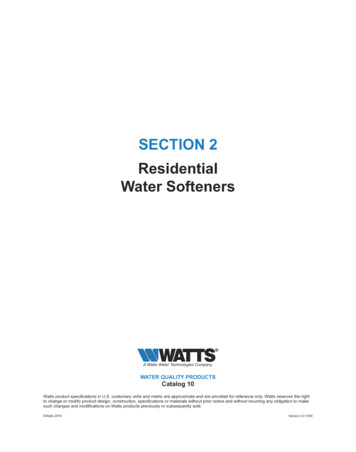
5. INLET/OUTLET PLUMBING: Be sure to install bypass valve onto main control valve beforebeginning plumbing. Make provisions to bypass outside hydrant and cold hard water lines at thistime. Install an inlet shutoff valve and plumb to the unit’s bypass valve inlet located at the right rearas you face the unit. There are a variety of installation fittings available. They are listed underInstallation Fitting Assemblies, page 24-25. When assembling the installation fitting package (inletand outlet), connect the fitting to the plumbing system first and then attach the nut, split ring and “O”Ring. Heat from soldering or solvent cements may damage the nut, split ring or “O” Ring. Solderjoints should be cool and solvent cements should be set before installing the nut, split ring and “O”Ring. Avoid getting solder flux, primer, and solvent cement on any part of the “O” Rings, split rings,bypass valve or control valve. If the building’s electrical system is grounded to the plumbing, install acopper grounding strap from the inlet to the outlet pipe. Plumbing must be done in accordance withall applicable local and state codes.6. INSTALLING GROUND: To maintain an electrical ground inmetal plumbing of a home’s cold water piping (such as a copperplumbing system), install a ground clamp or jumper wiring.NOTE: If replacing an existing softener, also replace the groundclamps/wire. If removing a softener, replace the piping with thesame type of piping as the original to assure plumbing integrityand grounding.7. DRAIN LINE: First, be sure that the drain can handle the backwash rate of the system. Solder jointsnear the drain must be done prior to connecting the drain line flow control fitting. Leave at least 6"between the drain line flow control fitting and solder joints. Failure to do this could cause interiordamage to the flow control. Install a 1/2" I.D. flexible plastic tube to the Drain Line Assembly ordiscard the tubing nut and use the 3/4" NPT fitting for rigid pipe (recommended). If the backwashrate is greater than 7 gpm, use a 3/4" drain line. Where the drain line is elevated but empties intoa drain below the level of the control valve, form a 7" loop at the discharge end of the line so thatthe bottom of the loop is level with the drain connection on the control valve. This will provide anadequate anti-siphon trap. Piping the drain line overhead 10 ft is normally not a problem. Besure adequate pressure is available (40-60 psi is recommended). Where the drain empties into anoverhead sewer line, a sink-type trap must be used with appropriate air gap (see drawing). Rundrain tube to its discharge point in accordance with plumbing codes. Pay special attention to codesfor air gaps and anti-siphon devices.Typical Drain Line Installations6
8. BRINE TANK CONNECTION: Install the 3/8" O.D. polyethylene tube from the Refill Elbow to theBrine Valve in the brine tank.9. OVERFLOW LINE CONNECTION: An overflow drain line is recommended where a brine overflowcould damage furnishings or the building structure. Your softener is equipped with a brine tank safetyfloat which greatly reduces the chance of an accidental brine overflow. In the event of a malfunction,however, an overflow line connection will direct the “overflow” to the drain instead of spilling on thefloor where it could cause considerable damage. This fitting is an elbow on the side of the brine tank.Attach a length of 1/2" I.D. tubing to fitting and run to drain. Do not elevate overflow line higherthan 3" below bottom of overflow fitting. Do not “tie” this tube into the drain line of the control valve.Overflow line must be a direct, separate line from overflow fitting to drain, sewer, or tub. Allow an airgap as per the drain line instructions.CAUTION: Never insert a drain line into a drain, sewer line,or trap. Always allow an air gap of 1-1/2" ortwice the pipe diameter, whichever is greater,between the drain line and the wastewater toprevent the possibility of sewage being backsiphoned into the conditioner.7
PROGRAMMING PROCEDURES:1. Set time of day:Time of day should only need to be set after extended power outages or when daylight saving time beginsor ends. If an extended power outage occurs, the time of day will flash on and off indicating that the timeshould be reset.STEP 1 – Press CLOCK.STEP 2 – CURRENT TIME (HOUR): Set the hour of the day using or — buttons.AM/PM toggles after 12. Press NEXT to go to step 3.STEP 3 – CURRENT TIME (MINUTES): Set the minutes using or — buttons. If it is desired toback up to the previous step press REGEN button once. Pressing NEXT will exit CLOCK andreturn to the general operating display (page 10).1232. Programming:NOTE: The manufacturer has preset the unit so that the gallons between regenerations will beautomatically calculated after the hardness is entered.STEP 1 – Press NEXT and simultaneously for 3 seconds.STEP 2 – HARDNESS: Set the amount of hardness in grains per gallon (default 20) usingthe or — buttons. The allowable range is from 1 to 150 in 1 grain increments.Note: Increase the grains per gallon if soluble iron is present (1ppm 4 gpg). Thisdisplay will show “–nA– (not available)” if “FILTER” is selected or if “AUTO” isnot factory set.Press NEXT to go to step 3. Press REGEN if you want to exit.STEP 3 – DAY OVERRIDE: The manufacturer has factory set 12 DAYS as the default.This is the maximum number of days between regenerations. If this is set to “OFF”,regeneration initiation is based solely on gallons used. If any number is set (allowablerange from 1 to 28), a regeneration initiation will be called for on that day even if asufficient number of gallons were not used to call for a regeneration.Set Day Override using or — buttons (12 is recommended): set number of days between regeneration (1 to 28); or set to “OFF”.Press NEXT to go to step 4. Press REGEN if you need to return to the previous step.1238
2. Programming cont’d:STEP 4 – REGENERATION HOUR: The manufacturer has factory set 2:00 A.M. as the default. Thisis the hour of day for regeneration and can be reset by using or — buttons. “AM/PM”toggles after 12. The default time is 2:00 a.m. (recommended for a normal household).Press NEXT to go to step 5. Press REGEN if you need to return to the previous step.STEP 5 – REGENERATION MINUTES: Set the minutes using or — buttons. Press NEXT to exitinstaller programming. Press REGEN if you need to return to the previous step. To initiatean immediate manual regeneration, press and hold the REGEN button for three seconds.The system will begin to regenerate immediately. The control may be manually steppedthrough the regeneration cycles by pressing REGEN.45OPERATING DISPLAYS AND INSTRUCTIONS:1. GENERAL OPERATION: When the system is operating,one of three displays may be shown. Pressing NEXT willalternate between the displays. One of the displays isalways the current time of day. The second display showsthe current treated water flow rate through the system inGallons Per Minute. The third display is one of thefollowing: days remaining or volume remaining. Daysremaining is the number of days left before the systemgoes through a regeneration cycle. Capacity remaining isthe gallons that will be treated before the system goesthrough a regeneration cycle. The user can scroll betweenthe displays as desired.GENERAL OPERATION DISPLAYSIf a water meter is installed, the word “Softening” or“Filtering” flashes on the display when water is beingtreated (i.e. water is flowing through the system).2. REGENERATION MODE: Typically a system is set to regenerateat a time of no water use. If there is a demand for water when thesystem is regenerating, untreated water will be delivered. Whenthe system begins to regenerate, the display will change to includeinformation about the step of the regeneration process and the timeremaining for that step to be completed. The system runs through thesteps automatically and will reset itself to provide treated water whenthe regeneration has been completed.9REGENERATIONMODE
3. MANUAL REGENERATION: Sometimes there is a need toregenerate before the control valve calls for it. This may beneeded if a period of heavy water use is anticipated or whenthe system has been operated without salt. To initiate a manual regeneration at the nextpreset regeneration time, press and releaseREGEN. The words “REGEN TODAY” will flashon the display to indicate that the system willregenerate at the next regeneration time (set inProgramming, steps 4 and 5). If you pressed theREGEN button in error, pressing the button againwill cancel the command.MANUAL REGENERATION To initiate a manual regeneration immediately, press and holdthe REGEN button for three seconds. The system will begin toregenerate immediately. This command cannot be cancelled.Once a manual regeneration is initiated, the unit will go into the FILL position. This position allows water toenter the brine tank until it reaches the proper level. Once this position is complete, you will notice a 240Minute (4 hours) SOFTENING position. This 4-hour window allows the salt to dissolve and achieve properbrine strength. During these FILL and SOFTENING positions, you will have softened water available foruse. Once the unit advances to the BACKWASH position and subsequent positions thereafter (see Start UpInstructions for regeneration sequence), the water softener will deliver water, but it will be untreated.IMPORTANT: With the Dry Salt Storage Feature, the brine tank will refill 4 hours before the actualregeneration occurs. You may experience a small amount of noise for a short period of time at 10:00 p.m.(with typical setting) on the night that regeneration is to occur. This noise is only the brine tank filling and atno time during this process will you be without treated water.4. POWER LOSS AND BATTERY REPLACEMENT:The AC transformer comes with a 15 foot power cord and isdesigned for use with the control valve; the transformer shouldonly be used in a dry location.In the event of a power outage that is less than 24 hours, thecontrol valve will remember all settings and time of day. After 24hours, the only item that needs to be reset is the time of day andwill be indicated by the time of day flashing. All other settings arepermanently stored in the nonvolatile memory.If a power loss occurs that is less than 24 hours and the time ofday flashes, this indicates that the battery is depleted. The time ofday should be reset and the non-rechargeable battery should bereplaced. The battery is a 3 Volt Lithium Coin Cell type 2032 andis readily available at most stores. To access battery location,remove front cover (see diagram on page 14 for battery location).10BATTERY REPLACEMENT
5. ERROR MESSAGE: If the word “ERROR” and a number arealternately flashing on the display record the number and contactthe dealer for help. This indicates that the control valve was notable to function properly.ERROR6. BRINE TANK MAINTENANCE AND SALT: Refill the brine tank as necessary, making sure atleast 1/3 of the brine tank is full at all times. Without proper salt levels, the water softener maynot operate properly.Because “typical” settings of this water softener include a dry salt storage feature (no water inbrine tank between regeneration), the manufacturer recommends the use of solar salt for bestresults. The brine tank is manufactured for the use of solar, pellets or rock salt. If pellet or rocksalt is used, a cleaning of the brine tank every six months is recommended. If the dry saltstorage feature is not being utilized, block salt may be used.CAUTION: The manufacturer does not recommend the use of anyresin cleaners, nor placement of any resin cleaners intothe brine tank. This may be harmful to the watersoftener and for human consumption. Consult dealerfor proper cleaning instructions.11
START-UP INSTRUCTIONS:FLUSHING OF SYSTEM:To flush the system of any debris and air after installation is complete, please perform the following steps:1. Rotate bypass handles to the bypass mode (see Fig. 2 of page 4).2. Turn on inlet water and check for leaks in the newly installed plumbing.3. Fully open a cold water faucet, preferable at a laundry sink or bathtub without an aerator.4. Wait two to three minutes or until water runs clear, then turn water off and followstart-up instructions.System regeneration sequence is in the following order. (If it is desired to change this sequence, please referto the Dealer Manual or contact the manufacturer.)1) BRINE TANK REFILL2) 4 HOURS (240 minutes) OF SOFTENING MODE WHILE SALT IS DISSOLVING3) BACKWASH4) BRINE DRAW AND SLOW RINSE5) FAST RINSE6) END (return to service)The system is now ready for filling with water and for testing.1. With the softener in the bypass mode (Fig. 2 on page 4) and the control valve in normal operationwhere the display shows either the time of day or the gallons remaining, manually add 3" of water tothe regenerant tank.NOTE: If too much water is put into the brine tank during softener start up, it could result in a“salty water” complaint after the first regeneration.During the first regeneration the unit will draw out the initial volume of brine/regenerant and refill itwith the correct preset amount.2. With the softener in bypass mode, press and hold the REGEN button until the motor starts. Release button.The display reads “FILL” and the remaining time in this step is counting down. Since the regenerant tankwas already filled in Step 1 press REGEN again and the display will read SOFTENING 240 (During a fullregeneration this will be a 4 hour period for salt to dissolve). Press REGEN again to put the valve into“BACKWASH.” Once valve has stopped in position, unplug the transformer so that the valve will not cycleto the next position. Open the inlet handle of the bypass valve very slightly allowing water to fill the tankslowly in order to expel air.CAUTION: If water flows too rapidly, there will be a loss ofmedia to the drain.3. When the water is flowing steadily to the drain without the presence of air, slowly open the inlet valve.Restore power and momentarily press the REGEN button to advance the control to the “BRINE” position.4. The bypass is now in the diagnostic mode (Fig. 3 on page 4). Check to verify that water is beingdrawn from regenerant tank with no air leaks or bubbles in the brine line. There should be a slow flowto the drain.12
5. Momentarily press REGEN again until the display reads “RINSE.” There should be a rapid flow to thedrain. Unplug transformer to keep the valve in the “RINSE” position. Allow to run until steady, clearand without air. While the unit is rinsing, load the brine tank with water softener salt (refer topage 9, Brine Tank Maintenance and Salt). Restore power.6. Place bypass valve in the normal operating mode (Fig. 1 on page 4) by opening the outlet bypasshandle. Press REGEN and the unit will return to the service position with time of day being displayed.7. CONDITIONING OF MEDIA:To flush any remaining debris and air from the system again:1. Full open a cold water faucet, preferably at a laundry sink or bathtub without an aerator.2. Wait two to three minutes or until water runs clear, then turn water off.3. Turn on hot water and check for air, then turn water off after air is discharged.8. SANITIZING OF UNIT UPON INSTALLATION AND AFTER SERVICE:At this time, it is advised to sanitize the softener:1. Open brine tank and remove brine well cover.2. Pour 1 oz. of household bleach into the softener brine well.3. Replace brine well cover.NOTE: Avoid pouring bleach directly onto the safety float components in the brine well.Unit sanitizing will be complete when the first cycle is run and the bleach is flushed from the softener.9. Check time of day. Start-up is now complete.13
TROUBLESHOOTING GUIDE:PROBLEMTimer doesnot displaytime of dayTimer does notdisplay correcttime of day ortime of dayflashesNo softening/filtering displaywhen water isflowingCAUSECORRECTIONA. transformer unpluggedA. reconnect transformerB. no power at outletB. repair or use working outletC. defective transformerC. replace transformerD. defective PC boardD. replace PC boardA. outlet is on a switchA. use unswitched outletB. power outageB. reset time of day; if due to a poweroutage of less than 24 hours, resettime of day and replace battery(see instructions on page 9)C. defective PC boardC. replace PC boardA. bypass valve in bypass positionA. put bypass in service positionB. meter cable disconnectedB. reconnect PC boardC. restricted/stalled meter turbineC. remove meter and check for debrisD. defective meterD. replace meterE. defective PC boardE. replace PC boardA. past power outageA. reset time of dayB. incorrect time of day displayedB. reset time of dayUnit regenerates C. time of regenerant set incorrectlyat wrong timeof dayD. control set at “on 0”Valve stalled inregenerationC. reset time of regenerationD. check with regeneration time option inprogrammingE. control set at “NORMAL on 0”E. check with regeneration time option inprogrammingA. motor not operatingA. replace motorsB. no power at outletB. repair outlet or use working outletC. defective transformerC. replace transformerD. defective PC boardD. replace PC boardE. broken drive gear or drive cap assemblyE. replace gear or drive cap assemblyF. broken piston retainerF. replace drive cap assemblyG. broken main or regenerant pistonG. replace main or regenerant piston14
PROBLEMValve doesnot regenerateautomaticallywhen REGENbutton is pressedValve doesnot regenerateautomaticallybut does whenREGEN button ispressedCAUSECORRECTIONA. transformer unpluggedA. connect transformer and PC board powerB. no power at outletB. restore powerC. broken drive gear or drive cap assemblyC. replace gear or drive cap assemblyD. defective PC boardD. replace boardA. bypass valve not in normal operating modeA. see bypass diagrams on page 4B. meter disconnectedB. reconnect to PC boardC. obstructed meter turbineC. clear obstructionD. defective meterD. replace meterE. programming errorE. review programmingF. defective PC boardF. replace boardERROR followed by code #A. valve has just been serviced (#1001)A. press NEXT and REGEN for 5 seconds ormomentarily unplug power source fromPC boardError code 1001:unable to recognizestart of regeneration B. motor gears not fully engaged —B. check motor wiringmotor wires broken — failed motor (#1001)Error code 1002:unexpected stallC. check piston and spacer stack forC. foreign material stuck in valve (#1002)Error code 1003:obstructionmotor ran too longD. excessive piston resistance (#1002)D. replace piston(s) and spacer stack assemblyError code 1004:motor ran too longError code 1009,2001, 4002, 4003,4004, 4010: circuitboard failureTWIN ALT SYSTEMSError code 1006:motor ran too longError code 1007:unexpected stallE. piston not in home position (#1004)E. press NEXT and REGEN for 5 seconds ormomentarily unplug power source fromPC boardF. center drive gear reflector dirty or damaged— missing or broken gear (#1004)F. replace or clean drive gear(s)G. drive bracket incorrectly aligned onbackplate (#1004)G. reset drive bracketH. PC board is damaged or defectiveH. replace PC board(#1009, 2001, 4002, 4003, 4004, 4010)I. PC board incorrectly aligned on drive bracketI. reset PC board onto drive bracket(#1009, 2001, 4002, 4003, 4004, 4010)If other codes appear, contact dealer.15
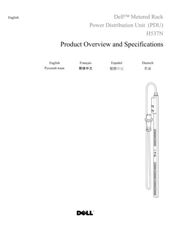
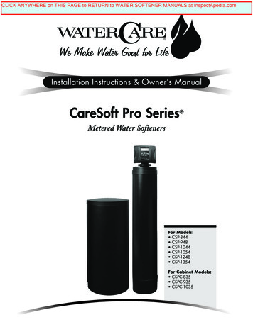
REPLACEMENT PARTS:FRONT COVER AND DRIVE ASSEMBLYItem No.Part No.DescriptionQty.1CV3837-01CareSoft Pro cover12CV3107-1Motor13CV3106-1Drive bracket & spring clip14CV3851WNPC board15CV3110Drive gear, 12 x 3636CV3109Drive gear cover17CV3002CC Drive assembly-CV3186Transformer, 110V-12V1CV3543Optional weather cover1NOTE: Battery Location146523716
REPLACEMENT PARTS:113145473821011PISTON ASSEMBLYItem No.1Part No.DescriptionQty.CV30051" spacer stack assembly1CV34301.25" spacer stack assembly12CV3004Drive cap assembly13CV3135O-ring 2281CV30111" piston assembly downflow14CV3011-011" piston assembly upflow1CV34071.25" piston assembly downflow15CV3174Regenerant piston16CV3180O-ring 33717CV3105O-ring 2151CV3556Screw, 1/4 - 20x1-1/2 18-8SS8910CV3016111213141CCI-00318337 Nut, 1/4 - 20 HEX 18-8SS1QC2 clamp assembly (includes screw & nut)1CV3452O-ring 2301CV3015WS1 QC2 Tank adapter assembly (includes O-rings)1CV30011" body assembly downflow11" body assembly upflow1CV30201.25" body assembly downflow1CV3541Drive backplate1CV3001UP1712679
REPLACEMENT PARTS:BYPASS VALVEItem No.Part CV3148CV3152CV3155CV3156DescriptionQty.Nut, 1" quick connectSplit ringO-ring 215Bypass rotor, 1"Bypass capBypass handleBypass rotor seal retainerO-ring 135O-ring 112O-ring 214222222222218
REPLACEMENT PARTS:INJECTOR ASSEMBLIESItem No.Part ot shownnot shownDescriptionInjector capO-ring 135Injector screenInjector assembly plugA injector assembly, BLACKB injector assembly, BROWNC injector assembly, VIOLETD injector assembly, REDE injector assembly, WHITEF injector assembly, BLUEG injector assembly, YELLOWH injector assembly, GREENI injector assembly, ORANGEJ injector assembly, LIGHT BLUEK
CareSoft Pro Series Metered Water Softeners For Models: CSP-844 CSP-948 CSP-1044 CSP-1054 CSP-1248 CSP-1354 For Cabinet Models: CSPC-835 CSPC-935 . but the water softener is not designed to support the weight of the plumbing. Do not use Vaseline, oils, other hydrocarbon lubricants or spray silicone anywhere. .