Transcription
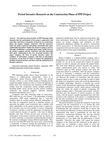
Distribution SubstationsCHAPTER 6
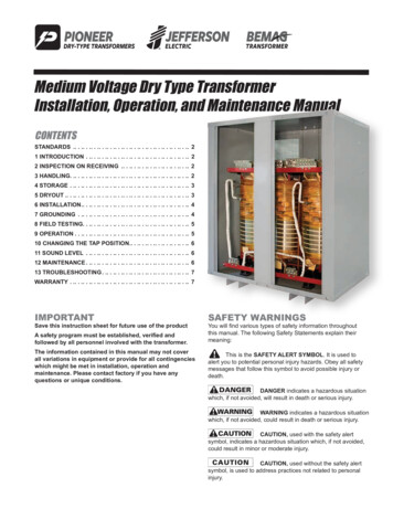
Electrical SubstationAn electrical substation is a subsidiarystation of an electricity generation,transmission and distribution systemwhere voltage is transformed from highto low or the reverse using transformers.Electric power may flow through severalsubstations between generating plantand consumer, and may be changed involtage in several steps.A substation that has a step-up transformerincreases the voltage while decreasing thecurrent, while a step-down transformerdecreases the voltage while increasing thecurrent for domestic and commercial distribution.
Substations generally have:1. Switching equipment2. Protection equipment3. Control equipment4. One or more transformersIn a large substation:Circuit breakers are used to interrupt anyshort-circuits or overload currents that mayoccur on the network.In smaller distribution stations:Recloser circuit breakers or fuses may be usedfor protection of distribution circuits.Other devices such as capacitors and voltage regulators may also be located at asubstation.Substations may be on the surface in fenced enclosures, underground, or located inspecial-purpose buildings.
Transmission substationA transmission substation connects two or more transmission lines.In case where all transmission lines have the same voltage:the substation contains high-voltage switches that allow lines to be connected orisolated for fault clearance or maintenance.A transmission station may have:1. Transformers to convert between two transmission voltages,2. Voltage control/power factor correction devices such as capacitors, reactors orstatic VAR compensators3. Phase shifting transformers to control power flow between two adjacent powersystems.Transmission substations can range from simple to complex.The large transmission substations can cover a large area (several acres/hectares) withmultiple voltage levels, many circuit breakers and a large amount of protection andcontrol equipment.
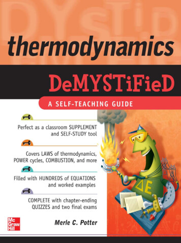
Distribution substationA distribution substation transfers power from the transmission system to thedistribution system of an area.The input for a distribution substation is typically at least two transmission orsubtransmission lines.Distribution voltages are typically medium voltage, between 2.4 and 33 kV dependingon the size of the area served and the practices of the local utility.Besides changing the voltage, the job of the distribution substation is to isolate faults ineither the transmission or distribution systems.Distribution substations may also be the points of voltage regulation, although on longdistribution circuits (several km/miles), voltage regulation equipment may also beinstalled along the line.Complicated distribution substations can be found in the downtown areas of large cities,with high-voltage switching, and switching and backup systems on the low-voltage side.
Collector substationIn distributed generation projects such as a wind farm, a collector substation may berequired, which is similar to a distribution substation although power flows in the oppositedirection, from many wind turbines up into the transmission grid.For economy of construction the collector system operates around 35 kV, and the collectorsubstation steps up voltage to a transmission voltage for the grid.The collector substation can also provide power factor correction if it is needed, meteringand control of the wind farm.Collector substations also exist where multiple thermal or hydroelectric power plants ofcomparable output power are in proximity.
Switching substationA switching substation is a substation which does not contain transformers andoperates only at a single voltage level.Switching substations are sometimes used as collector and distribution stations.Sometimes they are used for switching the current to back-up lines or forparalellizing circuits in case of failure.
DesignThe main considerations taking into account during the design process are:1. Reliability2. Cost (sufficient reliability without excessive cost)3. Expansion of the station, if required.Selection of the location of a substation must consider many factors:1. Sufficient land area2. Necessary clearances for electrical safety3. Access to maintain large apparatus such as transformers.4. The site must have room for expansion due to load growth or plannedtransmission additions.5. Environmental effects( drainage, noise and road traffic effects.6. Grounding must be taking into account to protect passers-by during a shortcircuit in the transmission system7. The substation site must be reasonably central to the distribution area to beserved.
LayoutThe first step in planning a substation layout is thepreparation of a one-line diagram which shows insimplified form the switching and protectionarrangement required, as well as the incomingsupply lines and outgoing feeders or transmissionlines.One-line diagram should include principal elements:LinesSwitchesCircuit breakersTransformersIncoming lines should have a disconnect switch and a circuit breaker.A disconnect switch is used to provide isolation, since it cannot interrupt loadcurrent.A circuit breaker is used as a protection device to interrupt fault currentsautomatically.Both switches and circuit breakers may be operated locally or remotely from asupervisory control center.
LayoutFollowing the switching components, the lines are connected to one or morebuses.An electrical bus, derived from bus bar, is a common electrical connectionbetween multiple electrical devices.Symbolic representation of a bus: The thick line is the bus, which representsthree wires. The slash through the bus arrow and the "3" means that the busrepresents 3 wiresThe arrangement of switches, circuit breakers and buses used affects the costand reliability of the substation.For important substations a ring bus or double bus.Substations feeding only a single industrial load may have minimal switchingprovisions.
LayoutOnce having established buses for the various voltage levels, transformers maybe connected between the voltage levels. These will again have a circuitbreaker in case a transformer has a fault.A substation always has control circuitry to operate the various breakers toopen in case of the failure of some component.
Switching functionSwitching is the operation of connecting and disconnecting of transmissionlines or other components to and from the system.Switching events may be "planned" or "unplanned".A transmission line or other component may need to be deenergized formaintenance or for new construction.To maintain reliability of supply, it is not cost efficient to shut down the entirepower system for maintenance.All work to be performed, from routine testing to adding entirely newsubstations, must be done while keeping the whole system running.Also, a fault may develop in a transmission line or any other component. Thefunction of the substation is to isolate the faulted portion of the system in theshortest possible time.
LoadThe size of the load to be served determines the capacity of the substation.The load must be distributed such that it can be served with reasonable feederloss or more.Critical loads (industrial districts) are served by more complex substations,designed for maximum reliability and speed of power restoration compare to theones used in residential areas where a short time power loss is usually not a disaster.Other substations in the area influence the design of a new substation.The presence of the other substations will increase the overall power capacity andas a result can satisfy the demand for heavy loads.
Substations for critical loads usually use more than one transformer so that theload is served even if one transformer is out.Otherwise a single large three-phase transformer is used because it costs lessper kVA of capacity, and requires less room, bussing, and simpler protectiverelaying.
Distribution Substation Protection NeedsAbove a minimum protection needed to avoid injury to people and damage to equipment,the level of protection of a substation is determined by how critical the loss of power is to theload.The loss of electrical power to a hospital is very serious while the loss of power to a residenceis inconvenient. In the event of a fault the hospital electricity must be restored in the shortestamount of time possible while the residence can be without electricity several hours without seriousconsequences.Equipping a substation with automaticswitching to restore power when it is lostand to assure the least possible damageand repair time after a fault is expensive.A small substation at the end of a radial subtransmission line that might be used to serve a small group ofresidences. It consists of two dead end poles to terminate the lines, two manual non-load break switches,and primary fusing.
Distribution Substation Protection NeedsThis substation can be used to serve a small commercial area.It has a circuit breaker as well as a primary fuse for back up, and more disconnect switches for isolationduring maintenance.The circuit breaker will operate from relays that require a metal clad enclosure, instrument transformers,and a de power supply for the trip circuit.The increased speed of fault removal supplied by the circuit breaker for this substation has substantiallyincreased its cost.Both substations are simple single-source, single-transformer, single-feeder types.The cost differences increase with the size of the substation, and the size and number of transformers used.
DISTRIBUTION SUBSTATION CONSTRUCTION METHODSFour basic methods exist for substation construction:1. Wood2. Steel lattice3. Steel low profile4. Unit.Wood pole substations are inexpensive, and can easily use wire bus structures. Wood is suitableonly for relatively small, simple substations because of the difficulty of building complex bus andswitch gear support structures from wood.Lattice steel provides structures of low weight and high strength. Complex, lattice steel isreasonably economical and is the preferred material for substation construction wheneverpossible.Solid steel low profile substations are superior to lattice or wood constructed substations.However, low profile construction is more expensive than either wood or lattice steel, and requiresmore land because multilevel bus structures cannot be used.The unit substation is a relatively recent development. A unit substation is factory built and tested,then shipped in modules that are bolted together at the site.Unit substations usually contain high and low voltage disconnect switches, one or two three-phasetransformers, low voltage breakers, high voltage fusing, bus work, and relays.
DISTRIBUTION SUBSTATION LAYOUT1. Single source, single feeder substationThe one-line diagram of a single-source, single-feedersubstation with the minimum equipment used.A bypass switch is provided so service can continue duringcircuit breaker maintenance.The probability of a fault during circuit breaker maintenanceis small, but still there as a result the transformer is protectedby a primary fuse to back up the breaker, and providesome protection for internal transformer faults.The minimum relaying is overcurrent on the secondary sideof the transformer.The switches can be manually or motor operated.
2. Single bus substationThis is the one line of a single bus substationfed by a single radial subtransaission line.Each feeder must has its own overcurrentprotection.The primary switch must be able to break thetransformer excitation current.The transformer may have differential relayingthat trips all of the feeder breakers in the event ofa fault.Each distribution voltage the substation suppliesmust have its own bus.The possibility of a subtransmission circuit fault ismuch higher than a transformer fault. Two sourcesallow service to be restored more quickly upon asubtransmission circuit fault.
2. Single bus substationThis is the one line of a double throw switch on the primary side which allows the transfer to bemade quickly from one subtransmission circuit to another.The switch is interlocked with the transformer breaker so it cannot be opened under load.The switch can be replaced by two manual high voltage breakers that can break the load, andexpected fault current.The transformer secondary breaker makes possible very effective differential bus protection todetect faults internal to the bus. The bus relays then trip all of the circuit breakers connected to thebus upon a bus fault.
3. Two Transformer Distribution SubstationsMore critical loads implement a two transformer distributionsubstation allowing to significantly decrease the out of service time.Normally the transformers are rated at 75% capacity when selfcooled and equipped with automatic air cooling that is used whenone transformer must handle the entire substation capacity.The tie switch between the two transformer connections to the buswhich is in open state when both transformers are in use to preventthe transformer secondaries from operating in parallel.Momentary parallel operation during switching is often permissiblebut must be avoided for the extended operation time due to the highsecondary currents.The primary side switching is arranged so that either or bothtransformers can be fed by either subtransmission line.
4. Automatic Switching (Throw-over)Two source, radial arrangementService outage time can be reduced considerably by usingcircuit breakers to automatically, or on command from acentral control station, disconnect the faulted source or busand connect the substation so that power can reach all ofthe feeders.Figure shows a substation connected for automatic switching,also called throw-over or roll-over.Operation:Assume sources 1 and 2 are connected as radial lines.1. Source 1 is lost, breaker 1 will open under relay controldisconnecting source 12 . Breaker 3 closes connecting transformer 1 to source 2,and vice versa.3. If transformer 1 fails, breakers 1, 3, and 4 would opento disconnect it.The low voltage bus tie breaker 6 closes to connect allof the feeders to transformer 2The low voltage tie breaker is interlocked withtransformer secondary breakers 4 and 5 to preventparallel transformer operation.
4. Automatic Switching (Throw-over)Loop ArrangementA preferred automatic switching scheme for loopconnected supply lines is shown.Circuit breakers A and B remove a faulted line fromservice, while circuit breakers C and C’ and D and D’remove the transformers in the event they fault.Upon a transformer failure the low voltage tie breakerconnects all of the working feeders to whichevertransformer is working.
Bus ArrangementsThe ring bus requires only one circuit breaker per line so it iseconomical.Power can reach any feeder from two directions so no feederneed be disconnected when one breaker is down for service.Two breakers are operated when a feeder fault occurs, one oneither side of the feeder.If a second breaker trips when one feeder is down the entirebus may be disconnected from a source.The ring bus is therefore seldom used if the feeders exceedthe source lines by than a factor of two.The breaker an a half is a reasonably economical, versatile,Reliable and as a result is very popular.A bus or feeder fault can easily be isolated while the stationremains in service.The breaker and a half is usually used in substations withmore than four feeders.
TRANSMISSION LINE FAULT CALCULATIONSA system fault is defined as any abnormal condition.Fault Classifications :1.Line to ground.Line to ground faults are caused by a line touching the ground.Wind, ice loading, tree falling on a line can cause a line to ground fault.This category accounts for about 70% of all line short circuit faults.25
Fault Classifications :2. Line to line.These faults are caused by high winds blowing one line into another, or by a line breaking andfalling on a line below it.These account for about 15% of line faults.26
Fault Classifications :3. Double line to ground.This category is caused by the same things that cause single line to ground faults, except twolines are involved instead of one.These account for about 10% of line faults.27
Fault Classifications :4. Three-phase faults.If a line condition occurs in which all three phases are shorted together, an equipment failure,or all three lines falling to the ground, it is called a three-phase fault.Accounts for only about 5% of all line faults.28
The point at which a conductor touches ground or another conductor during a fault is usuallyaccompanied by an arc.The arc is resistive, but arc resistance varies widely.The usual utility practice is to consider the fault resistance zero to calculate the maximum faultcurrent that can occur at a point of interest on a line.The fault current that flows depends on the source, line, and fault impedances:29
DISTRIBUTION SUBSTATION PROTECTIONCircuit breakers tripped by protective relays are used to protect theequipment within a substation, with primary fusing used to protect thetransformers in some smaller substations.Each relay set and circuit breaker is set to protect a certain portion ofthe substation and restrict the amount of the substation removed fromservice for a given fault.The portion of the substation removed from service by a given relayset is its zone of protectionEach protective element normally has a backup in this manner toprovide protection if the first line protection fails to operate.
Transformer ProtectionTransformers are very expensive, andso are well protected.A substation transformer has aminimum of:1. Secondary overcurrent relaying2. Primary fusing3. Sudden pressure relay.The sudden pressure relay (SPR) is arelay, attached to a valve on thetransformer that will detect the suddenrise in pressure caused by internal arcingand trip the secondary breaker.The SPR will not respond to the gradualrise in pressure caused by an increase inloading.Except for very small substationstransformers also have differentialrelaying with back-up overcurrentrelaying.
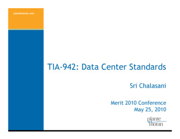
Transformer ProtectionFigure shows a one-line drawing of a well-protectedtransformer.The back-up primary overcurrent protection can useseparate CTs than the differential relays.A number of different ground fault protection possibilitiesare shown in the figure.The 50N/5IN in the primary overcurrent relaying.A good place to detect a ground fault in a grounded Ysystem is on the neutral to ground conductor.No current should flow in this conductor unless a groundfault exists.Resistors are used in the ground conductor to limit thetransient voltage from line capacitance charging on longsubtransmission and transmission lines, and to limitcurrent in the event of a fault from a phase to ground.
Bus ProtectionDifferential protection is effective for bus faults because the current leaving the bus onfeeders and the current entering the bus from sources should be zero at any instant.Additionally, differential protection can distinguish between internal bus faults and externalfeeder faults. A feeder fault can result in the CTs on the feeder saturating, and the dc offsetof a fault worsens the situation. Thus special care must be taken in bus differential relayingto prevent external faults from causing a trip on the circuit breakers supplying the bus.Three major systems are used: .1. Linear coupler (LC) system, which works by eliminating the iron core of the CTs.2. Multi-restraint, variable percentage relays (CA-16).3. High impedance voltage operated differential relays (KAB).
Linear coupler systems use air core transformersthat do not saturate.The LC system is fast, less than 16 ms for LC-land 32 ms for LC-2 relays.The LCs are actually designed to provide 5 Vsecondary voltage, detected by the relay, forevery 1000 A primary current.The LC connection for a very small bus is shown.The LCs are connected in series.Air-core transformersThese are used for high frequency work. The lackof a core means very low inductance. Suchtransformers may be nothing more than afew turns of wire.In normal operation or during an external fault thesum of the LCs voltages is zero because the LCvoltages are proportional to the line current andthe source and feeder currents sum to zero.During a bus fault at least one of the feedercurrents approaches zero and its LC voltagedrops. The voltage sum of the LCs is no longerzero and the relay operates.
Multi-restraint differential schemes use conventional CTs, which saturate on heavy external faults. In adifferential scheme, the current transformers and relay function as a team. When the current transformers donot perform adequately, the relay can within limits make up for the deficiency.The multirestraint differential scheme uses the CA- 16 variable-percentage differential relay, which consists ofthree induction restraint units and one induction operating unit per phase. Two of the units are placed oppositeeach other and operate on a common disc. In turn, the two discs are connected to a common shaft with themoving contacts.All four of the units are unidirectional; that is, current flows in either direction through the windings generatescontact-opening torque for the restraint units or contact- closing torque for the operating unit.Each restraint unit (R, S, and T) also has two windings to provide restraint proportional to the sum or difference,depending on the direction of the current flow. If the currents in the two paired windings are equal and opposite,the restraint is cancelled. Thus, the paired restraint windings have a polarity with respect to each other. Withthis method six restraint windings are available per phase.
The KAB is a high impedance differential relayThe high impedance differential KAB relay consists of aninstantaneous overvoltage cylinder unit (V), a voltagelimiting suppressor (varister), an adjustable tuned circuit,and an instantaneous current unit (IT).On external faults, the voltage across the relay terminalswill be low, essentially 0, unless the CTs are unequallysaturated.On internal faults, the voltage across the relay terminalswill be high and will operate the overvoltage unit.The varistor limits the voltage to a safe level.Since offset fault current or residual magnetism exists inthe CT core, there is an appreciable dc component in thesecondary current. The dc voltage that appears acrossthe relay will be filtered out by the tuned circuit, preventingrelay pickup.The IT current unit provides faster operation on severeinternal faults and also backup to the voltage unit.The KAB relay has successfully performed operations upto external fault currents of 200 A secondary and typicaloperating speed is 25 msec.
SUBSTATION GROUNDINGSubstation grounding is done safety, and to provide a stable reference voltage for protection systems.The grounding system of a substation consists of a ground mat made of large size bare conductors,connected in a grid pattern, and buried beneath the substation.The perimeter of the grid is connected to metal rods driven about 30 feet into the ground. The grid wiresare about 20 feet apart but the spacing varies with the conductivity of the soil.Highly conductive soil can use larger grid wire spacing.All substation structures are to be constructed within the perimeter of the grid.The fence around a substation has two buried ground wires connected to the fence every few feet.One runs about 3 feet outside the fence, and one inside the fence.Both wires are connected to grounding rods every 50 feet.
Sources:1. “Electrical Power Distribution and Transmission”, L.M Faulkenberry and W. Coffer.2. http://en.wikipedia.org/wiki/Electrical substation3. ection
Distribution substation A distribution substation transfers power from the transmission system to the distribution system of an area. The input for a distribution substation is typically at least two transmission or subtransmission lines. Distribution voltages are typically medium voltage, between 2.4 and 33 kV depending on the size o