Transcription
TECHNICAL SPECIFICATIONFORG83-6000Revision: 01Page 1 of 32LABTBEQS-TVKT
Technical Specification G83-6000Page 2 von 32Rev: 01MODIFICATIONSRev.ModificationDaterevised ---aFirst Issue04.05.1994Mr. GreinerbPkt. 2.7. Type plate printing changed to14.07.1994Type plate legendsData will be laser printed changed toData are partially moulded with the lower housingthe remaining type-marking will bei LASER-printedPkt. 2.9.6.Dimensions: 495 x 212 x 48 addedcCIRCULATION: S. Rodway addedPkt. 3.1.1.Current consumption: 45mA typical changed toCurrent consumption: 35mA typicalfPkt. 3Pkt. 1.3.Pkt. 1.4.Pkt. 7Pkt. 2.9.4.Pkt. 2.9.6.gMr. Greiner03.08.1994Mr. GreinerElectronic reworked05.10.1994Mr. Köferlweighs with original pack. 890g21.12.1994Mr. Greinerchanged to 1193gweighs without orignal pack. 750gchanged to 1040gOperating life 20 mill. operations changed toAlphanumeric keys min. 20 mill. actuation,Functionalkeys min. 4 mill. actuationApprovals: Novel Unix Ware and Novell Net Ware addedMaterial corrugated board. changed to corrugated board:Minimum requirement:Outer layer: 125 Kraftliner, Corrugation: 110,Inner layer: 140 TestlinerDimensions: 495x 212 x 48 changed to 495 x 210 x 47Pkt. 1.3. Weight with the original packaging approx 1193g changed to1190gPkt. 1.6. Keyboard designation G80-6000LAD changed G80-6000LAADEPkt. 2.4.2.and lower grid addedPkt. 2.4.3.PET, 100µm thick changed to textured PET, 125µm thickPkt. 2.7.Type plate legends changed to Name plate legendsPkt. 3.Electronic reworkedPkt. 4.1.1.Operation min. 0 to 40 C, desired 0 to 50 C changed to desired 0 to 50 CPkt. 4.2.1.10 to 85 degree changed to 10 to 85%Pkt. 4.2.2.10 to 95 degree changed to 10 to 95%Pkt. 4.2.3.10 to 95 degree changed to 10 to 95%Pkt. 4.3.1.85 degree changed to 85%Pkt. 4.4.1.10 to 22,5 Hz, travel. changed to 10 to 22,5 Hz, displacement.Pkt. 4.4.2.10 to 16 Hz: travel. changed to 10 to 16 Hz, displacementPkt. 4.5.1.(halfsine wave) added
Technical Specification G83-6000Page 3 von 32Rev: 01Rev.ModificationDaterevised ---Pkt. 4.5.2.(halfsine wave) addedPkt. 4.6.1.Operation: withstands having. changed to bench test to bottom side.Pkt. 4.7. Air pressure changed to AlitudePkt. 5.Electromangnetic Compatibilit reworkedPkt. 6.Reliability reworkedPkt. 7.Approvals UL changed to UL 1950Pkt. 8.EC Conformity for „CE“-mark added00Pkt. 1.1. Description 104/104 keys addedPkt. 1.6. Keyboard desgnation G80-6000 changed to G83-6000Pkt. 2.2.3.Keycaps number, sizes 104/105 key addedPkt. 2.4.3.Spacer 125 µm changed to 100 µmPkt. 3.3.2.Typical Power on Diagram addedPkt. 3.5.1.Key numbering 104/104 keys addedPkt. 3.5.2.No. 52/63/65 in Codetable obsoletedPkt. 3.5.2.1.Appendix 1 for Set 1 addedPkt. 4.7.1. equivalent to 565 changed to 665 mbarsPkt. 4.7.2. equivalent to 226 changed to 280 mbarsPkt. 6.2.1.Nominal workload changed to Electronics.Pkt. 6.2.2.Maximumum average workload changed to keyboard.Pkt. 6.2.3.obsoleted01Pkt. 2.4.3.complete revised13.07.1998E. Goß(Änd.-Nr. 128280)
Technical Specification G83-6000Page 4 von 32Rev: 8.1.9.1.10.1.11.1.12.1.13.DESCRIPTIONKEYBOARD COMPONENTSWEIGHTOPERATING LIFEFORCE/TRAVEL DIAGRAMKEYBOARD DESIGNATIONHOUSING/LEGEND VERSIONSTECHNICAL DESIGNLANGUAGE/COUNTRY VERSIONSGENERAL REQUIREMENTS AS PER DIN/ISOERGONOMICSUL RECOGNITION1.12.1. Plastic parts1.12.2. PCB1.12.3. Cables1.12.4. Membranes1.12.5. Rubber sheetADDITIONAL DOCUMENTS2.0.MECHANICAL COMPONENTS2.1.HOUSING2.1.1. Colour2.1.2. Dimensions2.1.3. Materials2.1.4. Surface2.1.5. Adjustable feet2.1.6. Antislip pads2.1.7. Inclination2.1.8. CleaningKEYCAPS2.2.1. Shape2.2.2. Colour2.2.3. Number, sizes2.2.4. Material2.2.5. Surface2.2.6. Legends2.2.6.1 Type of top legend2.2.6.2. Colour of top legend2.2.6.3. Type of front legend2.2.6.4. Colour of front legend2.2.6.5. Type style2.2.7. Layout, position2.2.7.1. Height of C row2.2.7.2. Alphanumeric field2.2.7.3. Deviation from baseline2.2.
Technical Specification G83-6000Page 5 von 32Rev: 012.3.2.4.2.5.2.6.2.7.2.8.2.9.2.2.7.4. Gap between adjacent keycaps2.2.8. Pull-out forceRUBBER SHEET2.3.1. Material2.3.2. Tactile SpacerPCB2.5.1.Design2.5.2.Colour of solder gn2.6.2.Colour2.6.3.Length2.6.4.PlugNAME PLATE LEGENDSLED . ELECTRONICS3.1.3.2.3.3.ELECTRICAL CHARACTERISTICS3.1.1.Power supply3.1.2.Connector Assignment3.1.3.PCB Connector AssigmentINTERFACE3.2.1.Data Output Signal3.2.2.Data communications3.2.3.Clock and Data Signals3.2.4.Timing diagram3.2.5.Keyboard sends Data3.2.6.Keyboard receives data3.2.7.Keyboard BufferPOWER-ON ROUTINE3.3.1.Power-On Reset3.3.2.Typical Power On Diagramm3.3.3.Basic Assurance Test
Technical Specification G83-6000Page 6 von 32Rev: 013.4.3.5.3.6.COMMANDS3.4.1. Commands from the System3.4.1.1. Default Disable (Hex F5)3.4.1.2. Echo (Hex EE)3.4.1.3. Enable (Hex F4)3.4.1.4. Invalid Command (Hex EF and F1)3.4.1.5. Read ID (Hex F2)3.4.1.6. Resend (Hex FE)3.4.1.7. Reset (Hex FF)3.4.1.8. Select Alternate Scan Codes (Hex F0)3.4.1.9. Set All Keys (Hex F7, F8, F9, FA)3.4.1.10. Set Default (Hex F6)3.4.1.11. Set Key Type (Hex FB, FC, FD)3.4.1.12. Set/Reset Status Indicators (Hex ED)3.4.1.13. Set Typematic Rate/Delay (Hex F3)3.4.2. Commands to the System3.4.2.1. Acknowledge (Hex FA)3.4.2.2. BAT Completion Code (Hex AA)3.4.2.3. BAT Failure Code (Hex FC)3.4.2.4. Echo (Hex EE)3.4.2.5. Keyboard ID (Hex 83AB)3.4.2.6. Key Detection Error (Hex or FF)3.4.2.7. Overrun (Hex 00 or FF)3.4.2.8. Resend (Hex FE)KEYCODES3.5.1. Key numbering3.5.2. Codetable3.5.2.1. Appendix 1 for Set 13.5.2.2. Appendix 1 for Set 2CABLE DRAWINGS4.0. ENVIRONMENTAL .5.1.Operation4.5.1.Storage and transport
Technical Specification G83-6000Page 7 von 32Rev: 014.6.4.7.Drop resistance4.6.1.Operation4.6.2.Storage and transportAltitude4.7.1.Operation4.7.2.Storage and transport5.0. ELECTROMAGNETIC COMPATIBILITY5.1.5.2.5.3.5.4.RFI/EMIESD susceptibilityImmunity to radiated fieldsBurst ectronics6.2.2.Keyboard7.APPROVALS8.EC CONFORMITY FOR „CE“-Mark8.1.8.2.SaftyElectro-Magnetic Compatibility8.2.1.RFI8.2.2.Susceptibility
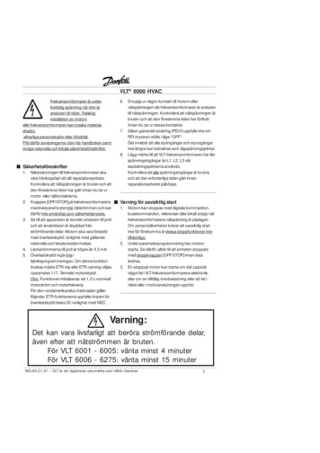
Technical Specification G83-6000Page 8 von 32Rev: 011.0.GENERALThis specification describes the requirements for the G83-6000.1.1.PRODUCT DESCRIPTIONThis is a keyboard with 101/102 or 104/105 keys in a housing with Cherry adjustablefeet. No options are planned.G83 ------- Rubber sheet technology1.2.KEYBOARD COMPONENTSThe keyboard consists of the following principal parts:a) Upper housing with light conveyor and keycapsb) Lower housing, adjustable feet and antislip padsc) Membrane assemblyd) Rubber sheete) Printed wiring board with electronic componentsThe upper housing is snapped onto the lower housing. The printed wiring board,the rubber sheet and the membrane are placed in the lower housing. Themembrane contacts the PCB by being pressed against it.1.3.WEIGHTThe keyboard weighs with the original packaging:without the original packaging:1.4.OPERATING LIFEAlpha-Keypad: min. 20 mill actuationFunctional keys min. 4 mill. actuation1.5.FORCE/TRAVEL DIAGRAMapprox. 1190 gapprox. 1040 gKraftforcef (cN)(CN)70Druckpunkt / tactilepoint605040DF302010Vorlaufweg / pretravel1Nominal values:233,74Wegtravels (mm)
Technical Specification G83-6000Page 9 von 32Rev: 01Tactile point:Pretravel:Total travel:Force differential:1.6.0,9mm / 61 cN2,4 mm3,7 mm26 cNKEYBOARD DESIGNATIONG83-6000LAADECountry/language versionTechnical versionHousing/legend versionKeyboard number1.7.HOUSING/LEGEND VERSIONL with housing/laser-printed keycapsNo other letters are specified1.8.TECHNICAL DESIGNFor detailed listing see DOKT-6000-03 "Technical design"1.9.COUNTRY/LANGUAGE VERSIONFor detailed listing see DOKT-6000-04 "Letter designation for country/languageversions"1.10.GENERAL REQUIREMENTS FOR KEYBOARDS IN COMPLIANCE WITH ISO 9995AND DIN 21371.11.ERGONOMICS AS PER ISO 9241 PART 4, ZH 1/6181.12.UL-RECOGNIZED MATERIALS/FIRE PROTECTION CLASSES1.12.1. Plastic parts:UL 94 HB1.12.2. Circuit boards: UL 94 V-O1.12.3. Cables:UL-recognized1.12.4. Membranes:UL 4 VTM-21.12.5. Rubber sheet: UL 94 HB1.13.Additional documentsDrawings of individual partsSymbol filmsFAW'sVAW'sDOKZ-6000-01Design printsDOKT-6000-02Construction overviewDOKT-6000-03Technical designDOKT-6000-04Letter designations forcountry/language versions
Technical Specification G83-6000Page 10 von 32Rev: 012.0.MECHANICAL COMPONENTS2.1.HOUSING2.1.1. Colour2.1.2. Dimensions2.1.3. Material2.1.4. Surface2.1.5. Adjustable feet:2.1.6. Anti-slip pads2.1.7. Inclination2.2.KEYCAPS2.2.1. Shape:2.2.2. Colour/colour code2.2.3. Number, sizes:pearl white458 x 170 mmS/B Styrene / butadieneas per VDI 3400 No. 36; Ra 6,3 µm2, with antislip pads2 pcs.6 and 10 cylindrical ("cyln"), type unilevelwhite-grey/beige-grey / 6A/6BVersion with 101 keys:83x1x13x1x1 with dimple (F/J/5) 6A6x1x1,51x1x1,75 stepped6B2x1x22x1x2,252x1x2 vertical1x1x2,751x1x7Version with 102 keys:85x1x13x1x1 with dimple (F/J/5) 6A1x1x1,255x1x1,51x1x1,75 stepped6B2x1x22x1x2 vertical1x1x2,751x1,5x2x1,251x1x7Version with 104 keys83x1x13x1x1 with dimple (F/J/5) 6A7x1x1,252x1x1,51x1x1,75 stepped6B2x1x22x1x2 6A
Technical Specification G83-6000Page 11 von 32Rev: 01Version with 105 keys85x1x13x1x1 with dimple (F/J/5) 6A8x1x1,251x1x1,51x1x1,75 stepped6B2x1x22x1x2 vertical1x1x2,751x1,5x2x1,251x1x6,252.2.4. Material2.2.5. Surface2.2.6. Legends:2.2.6.1. Type of top legend:2.2.6.2. Colour/colour code of top legend:2.2.6.3. Type of front legends:6A/6B6B6B6A/6B6B6B6B6APBTeroded, Rt 18 µmlaser-printedblacklaserprinted/tampoprinting optionallypossible2.2.6.4. Colour of front legends:2.2.6.5. Typestyle:blackFormula One2.2.7. Layout, position2.2.7.1. Height of C row2.2.7.2. Typewriter area:2.2.7.3. Deviation from baseline of a row:2.2.7.4. Gap between two adjacent keycaps:2.2.8. Pull-off force:2.3.RUBBER SHEET2.3.1. Material:2.3.2. Tactile feedback:2.4.MEMBRANE2.4.1. Membrane material:2.4.2. Printing:2.4.3. Spacer:29,5 mmas per DIN 2137 0,5 mmVariance of /- 0,5mm6N F 30 Ntwo-component silicone rubber(LSR)tactile pointPET, 100 µm thickTracks with conductive silverink approx 7 µmthick, plus carbonprinting on outside of uppermembrane and lower gridPET, 100 µm thick textured /embossed up to 125 µmthickness
Technical Specification G83-6000Page 12 von 32Rev: 012.5.PCB2.5.1. Type:2.5.2. Colour:2.5.3. Dimensions:2.5.4. Material:2.6.CABLES:2.6.1. Type:2.6.2. Colour:2.6.3. Length:2.6.4. Connector:one side with Cu 35/00 µm chem. nickel 4 - 5 µmchem. gold 0,1 - 0,3 µmsolder resist, green, on solder side59 x 27,5 x1,5 mmFR2 (UL 94 V-0) orFR1 (UL 94 V-0) orFR3 (UL 94V-0) orFR4 (UL 94V-0)round with and without coilgravel-grey (RAL 7032)1750 mm from housing in version without coil5-pin shielded DIN connector or mini-DINconnector other end plug connected2.7.NAME PLATE LEGENDSData are partially moulded in bottom housing, the additional datas will be Layerprinted2.8.LED LEGENDSLaser-printed on upper housing2.9.PACKAGING2.9.1. Type:2.9.2. Colour:2.9.3. Printing:2.9.4. Material:2.9.5. Labels:2.9.6. Dimensions:single packaging; corrugated collapsible boxboardbrownnonecorrugated boardMinimum requirement:Outer layer: 125 KraftlinerCorrugation: 110Inner layer: 140 Testlinerprinted paper495 x 210 x 47
Technical Specification G83-6000Page 13 von 32Rev: 013.ELECTRONICS3.1ELECTRICAL CHARACTERISTICS3.1.1Power Supply3.1.2VoltageMin.4,75 VTyp.5VMax.5,25 Vsafety extra lowvoltage (SELV)Current 3 LED's ONCurrent 3 LED's OFFtbdtbd35 mA5 mAtbdtbdConnector AssignmentDIN Connector SignalsMINI DIN Connector1 Clock 52 Data 13 nc2/64 Ground 35 5 Volt 4Shell Shield Shell245513DIN3.2INTERFACE3.2.1Data Output Signal3ConnectorpinsFront-ViewMIN.02,4 VMAX.0,7 V5,25 V4MINIDIN1Bidirectional synchronous format. IBM-AT-compatible. Open drain.CLOCK/DATAVout lowVout high62
Technical Specification G83-6000Page 14 von 32Rev: 013.2.2Data communications1 Startbit (always 0)8 Databits1 Paritybit odd1 Stopbit (always 1)3.2.3Clock and Data SignalsThe keyboard and the system communicate over the clock and data lines. Thesource of each of theses lines is an open-drain device on the keyboard that allowseither the keyboard or the system to force a line to low level. When nocommunication is occurring, the clock and datalines are on high level kept by pull-upresistors.When the system sends data to the keyboard, it forces the data line to low leveluntil the keyboard starts to clock the data stream.The keyboard clock line provides the clocking signals used to clock serial data to andfrom the keyboard. If the host system forces the clock line to an low level, keyboardtransmission is inhibited.When the keyboard sends data to or receives data from the system it generates theclock signal to time the data. The system can prevent the keyboard from sendingdata by forcing the clock line to low level, the data line may be high or low duringthis time.During the BAT, the keyboard allows the clock and data line to go to high level.3.2.4 Timing 3Bit4Bit 5Bit6Bit7ParityStop
Technical Specification G83-6000Page 15 von 32Rev: 4Bit5Bit6Bit7ParityLine ControlBitT1T2T3T4T5T63.2.530 50µs30 50µs5 25µs5 T2-5µs0 50µs5 25µsKeyboard sends DataWhen the keyboard is ready to send data, it first checks for a keyboard-inhibit orsystem request-to-send status on the clock and data lines. If the clock line is low,data is stored in the keyboard buffer. If the clock line is high and the data line is low(request-to send), data is stored in the keyboard buffer, and the keyboard receivessystem data.If the clock and data lines are both high the keyboard sends the (0) start bit, 8 databits, the parity bit and the stop bit. Data will be valid before the trailing edge andbeyond the leading edge of the clock pulse. During transmission, the keyboardchecks the clock line for low level at least every 60 µseconds. If the system lowersthe clock line after the keyboard starts ending data, a condition known as linecontention occurs, and the keyboard stops sending data. If line contention occursbefore the leading edge of the 10th clock signal (parity bit), the keyboard bufferreturns the clock and data lines to high level. If contention does not occur by the10th clock signal, the keyboard completes the transmission. Following linecontention, the system may or may not request the keyboard to resend the data.Following a transmission, the system can inhibit the keyboard until the systemprocesses the input or until it requests that a response be sent.
Technical Specification G83-6000Page 16 von 32Rev: 013.2.6Keyboard receives dataWhen the system is ready to send data to the keyboard, it first checks to seeif the keyboard is sending data. If the keyboard is sending, but has notreached the 10th clock signal, the system can override the keyboard outputby forcing the keyboard clock line to low level. If the keyboard transmission isbeyond the 10th clock signal, the system must receive the transmission.If the keyboard is not sending or if the system elects to override the keyboard'soutput, the system forces the keyboard clock line to low level for more than 60microseconds while preparing to send data. When the system is ready to send thestart bit (the data line will be low), it allows the clock line to got to high level.The keyboard checks the state of the clock line at intervals of no more than10 milliseconds. If a system request-to-send (RTS) is detected, the keyboard counts11 bits. After the 10th bit, the keyboard checks for high level on the data line, and ifthe line is high forces it low, and counts one more bit. This action signals the systemthat the keyboard has received its data. Upon receipt of this signal, the systemreturns to a ready state, in which it can accept keyboard output or goes to theinhibited state until it is ready.If the keyboard data line is found at low level following the 10th bit, a framing errorhas occurred, and the keyboard continues to count until the data line becomes high.The keyboard then makes the data line low and sends a Resend.Each system command or data transmission to the keyboard requires aresponse from the keyboard before the system can send its next output. Thekeyboard will respond within 20 milliseconds unless the system preventskeyboard output. If the keyboard response is invalid or has a parity error, thesystem sends the command or data again. However, the two byte commandsrequire special handling. If hex F3 (Set Typematic Rate/Delay), hex F0 (SelectAlternate Scan Codes), or hex ED (Set/Reset Mode Indicators) have beensent and acknowledged, and the value byte has been sent but the responseis invalid or has a parity error, the system will resend both the command andthe value byte.3.2.7Keyboard BufferA 16-byte first-in-first-out (FIFO) buffer in the keyboard stores the scan codes untilthe system is readyto receive them.A buffer-overrun condition occurs when more than 16 bytes are placed in thekeyboard buffer. An overrun code replaces the 17th byte. If more keys are pressedbefore the system allows keyboard output, the additional data is lost.When the keyboard is allowed to send data, the bytes in the buffer will be sent as innormal operation, and new data entered is detected and sent. Response codesno occupy a buffer position.If keystrokes generate a multiple-byte sequence, the entire sequence must fit into
Technical Specification G83-6000Page 17 von 32Rev: 01the available buffer space or the keystroke is discarded and a buffer-overruncondition occurs.3.3.POWER-ON-ROUTINE3.3.1Power-On ResetThe keyboard logic generates a 'power-on-reset' signal (POR) when power is firstapplied to the keyboard. POR occurs a minimum of 150 milliseconds and amaximum of 2.0 seconds from the time power is first applied to the keyboard.3.3.2. Typical Power on Diagram 5 VoltsClockDataBAT Completion Code hex AAx ---- 500 ms -------- 345 ms -----xPOR DELAYBAT3.3.3 /-20%Basic Assurance TestThe basic assurance test (BAT) consists of a keyboard processor test, a checksumof the read-only memory (ROM), and a random-access memory (RAM) test. Duringthe BAT, activity on the "clock" and "data" lines is ignored. The LEDs are turned on atthe beginning and off at the end of the BAT. The BAT takes a minimum of300 milliseconds and a maximum of 500 milliseconds. This is in addition to the timerequired by the POR.Upon satisfactory completion of the BAT, a completion code (hex AA) is sent to thesystem, and keyboard scanning begins. If a BAT failure occurs, the keyboards sendsan error code to the system. The keyboard is then disabled pending command input.Completion codes are sent between 450 milliseconds and 2.5 seconds after POR,and between 300 and 500 millisecondsafter a Reset command is acknowledged.
Technical Specification G83-6000Page 18 von 32Rev: 013.4COMMANDS3.4.1Commands from the SystemThe following table shows the command that the system may send and theirhexadecimal values.CommandSet/Reset Status IndicatorsEchoInvalid CommandSelect Alternate Scan CodesInvalid CommandRead IDSet Typematic Rate/DelayEnableDefault DisableSet DefaultSet All Keys - Typematic- Make/Break- Make- Typematic/Make/BreakSet Key Type - Typematic- Make/Break- MakeResendResetHex ValueEDEEEFF0F1F2F3F4F5F6F7F8F9FAFBFCFDFEFFThe Commands may be sent to the keyboard at any time. The keyboard will respondwithin 20 milliseconds, except when performing the basic assurance test (BAT), orexecuting a Reset command.3.4.1.1 Default Disable (Hex F5)The Default Disable command resets all conditions to the power-on default state.The keyboard responds with ACK, clears its output buffer, sets the default key types(scan code set 3 operation only) and typematic rate/delay, and clears the lasttypematic key. The keyboard stops scanning and awaits further instructions.3.4.1.2 Echo (Hex EE)Echo is a diagnostic aid. When the keyboard receives this command, it issues a hexEE response and, if the keyboard was previously enabled, continues scanning.3.4.1.3 Enable (Hex F4)Upon receipt of this command, the keyboards responds with ACK, clears its outputbuffer, clears the last typematic key, and starts scanning.3.4.1.4 Invalid Command (Hex EF and F1)Hex EF and hex F1 are invalid commands and are not supported. If one of these is
Technical Specification G83-6000Page 19 von 32Rev: 01sent, the keyboard does not acknowledge the command, but returns a Resendcommand and continues in its prior scanning state. No other activities occur.3.4.1.5 Read ID (Hex F2)This command requests identification information from the keyboard. The keyboardresponds with ACK, discontinues scanning and sends the two keyboard ID bytes.The second byte must follow completion of the first by no more than500 microseconds. After the output of the second ID byte, the keyboard resumesscanning.3.4.1.6 Resend (Hex FE)The system sends this command when it detects an error in any transmission fromthe keyboard. It is sent only after a keyboard transmission and before the systemallows the next keyboard output. When a Resend is received, the keyboard sendsthe previous output again (unless the previous output was Resend, in which casethe keyboard sends the last byte before the Resend command).3.4.1.7 Reset (Hex FF)The system issues a Reset command to start a program reset and a keyboardinternal self test. The keyboard acknowledges the command with an ACK andensures the system accepts ACK before executing the command. The systemsignals acceptance of ACK by raising the clock and data lines for a minimum of500 microseconds. The keyboard is disabled from the time it receives the Resetcommand until ACK is accepted or until another command is sent that overrides theprevious command.Following acceptance of ACK, the keyboard is re-initialized and performs the BAT.After returning the completion code, the keyboard defaults to scan code set 2.3.4.1.8 Select Alternate Scan Codes (Hex F0)This command instructs the keyboard to select one of three sets of scan codes.The keyboard acknowledges receipt of this command with ACK, clears both theoutput buffer and the typematic key (if one is active). The system then sends theoption byte and the keyboard responds with another ACK. An option byte value ofhex 01 selects scan code set 1, hex 02 selects set 2 and hex 03 selects set 3.An option byte value of hex 00 causes the keyboard to acknowledge with ACK andsend a byte telling the system which scan code set is currently in use.After establishing the new scan code set, the keyboard returns to the scanning stateit was in before receiving the Select Alternate Scan Codes command.3.4.1.9 Set All Keys (Hex F7, F8, F9, FA)These commands instruct the keyboard to set all keys to the type listed below:
Technical Specification G83-6000Page 20 von 32Rev: 01Hex ValueF7F8F9FACommandSet All Keys - TypematicSet All Keys - Make/BreakSet All Keys - MakeSet All Keys - Typematic/Make/BreakThe keyboard responds with ACK, clears its output buffer, sets all keys to the typeindicated by the command and continues scanning (if it was previously enabled).Although these commands can be sent using any scan code set, they affect onlyscan code set 3 operation.3.4.1.10 Set Default (Hex F6)The Set Default command resets all conditions to the power-on default state. Thekeyboard responds with ACK, clears its output buffer, sets the default key types(scan code set 3 operation only) and typematic rate/delay, clears the last typematickey and continues scanning.3.4.1.11 Set Key Type (Hex FB, FC, FD)These commands instruct the keyboard to set individual keys to the type listedbelow:Hex ValueFBFCFDCommandSet Key Type - TypematicSet Key Type - Make/BreakSet Key Type - MakeThe keyboard responds with ACK, clears its output buffer and prepares to receivekey identification. Key identification is accomplished by the system identifying eachkey by its scan code value as defined in scan code set 3. Only scan code set 3values are valid for key identification. The type of each identified key is set to thevalue indicated by the command.These commands can be sent using any scan code set, but affect only scan codeset 3 operation.3.4.1.12 Set/Reset Status Indicators (Hex ED)Three status indicators on the keyboard - Num Lock, Caps Lock and Scroll Lock - areaccessible by the system. The keyboard activates or deactivates these indicatorswhen it receives a valid command-code sequence from the system. The commandsequence begins with the command byte (hex ED). The keyboard responds to thecommand byte with ACK, discontinues scanning and waits for the option byte fromthe system. The bit assignments for this option byte are as follows:
Technical Specification G83-6000Page 21 von 32Rev: 01Bit0123-7IndicatorScroll Lock IndicatorNum Lock IndicatorCaps Lock IndicatorReserved (bust be 0s)If a bit for an indicator is set to 1, the indicator is turned on. If a bit is set to 0, theindicator is turned off.The keyboard responds to the option byte with ACK, sets the indicators and, if thekeyboard was previously enabled, continues scanning. The state of the indicatorswill reflect the bits in the option byte and can be activated or deactivated in anycombination. If another command is received in place of the option byte, executionof the Set/Reset Mode Indicators command is stopped, with no change to theindicator states and the new command is processed.Immediately after power-on, the lights default to the Off state. If the Set Default andDefault Disable commands are received, the lamps remain in the state they were inbefore the command was received.3.4.1.13 Set Typematic Rate/Delay (Hex F3)The system issues the Set Typematic Rate/Delay command to change the typematicrate and delay. The keyboard responds to the command with ACK, stops scanningand waits for the system to issue the rate/delay value byte. The keyboard respondsto the Rate/delay value byte with another ACK, sets therate and delay to thevalues indicated and continues scanning (if it was previously enabled). Bits 6and 5 indicate the delay and bits 4, 3, 2, 1 and 0 (the least-significant bit) the rate. Bit7, the most-significant bit, is always 0. The delay is equal to 1 plus the binary valueof bits 6 and 5, multiplied by 250 milliseconds 20 %.
Technical Specification G83-6000Page 22 von 32Rev: 01The typematic rate (make codes per second) is 1 for each period and are listed in thefollowing te 20 aticRate 20 he default values for the system keyboard are as follows:Typematic rate 10.9 characters per second 20 %Delay 500 milliseconds 20 %The execution of this command stops without change to the existing rate if anothercommand isreceived instead of the rate/delay value byte.3.4.2Commands to the SystemThe following table shows the commands that the keyboard may send to thesystem and their hexadecimal values.CommandKey Detection Error/OverrunKeyboard IDBAT Completion CodeBAT Failure CodeEchoAcknowledge (ACK)ResentKey Detection Error/OverrunHex Value00 (Code Sets 2 and 3)83ABAAFCEEFAFEFF (Code Set 1)The commands the keyboard sends to the system are described below, inalphabetic order.
Technical Specification G83-6000Page 23 von 32Rev: 013.4.2.1 Acknowledge (Hex FA)The keyboard issues Acknowledge (ACK) to any valid input other than an Echo orResend command. If the keyboard is interrupted while sending ACK, it discards ACKand accepts and responds to the new command.3.4.2.2 BAT Completion Code (Hex AA)Following satisfactory completion of the BAT, the keyboard sends hex AA. Anyother code indicates a failure of the keyboard.3.4.2.3 BAT Failure Code (Hex FC)If a BAT failure occurs, the keyboard sends this code, discontinues scanning andwaits for a system response or reset.3.4.2.4 Echo (Hex EE)The keyboard sends this code in response to an Echo command.3.4.2.5 Keyboard ID (Hex 83AB)The Keyboard ID consists of 2 bytes, hex 83AB. The keyboard responds to the ReadID with ACK, discontinues scanning, and sends the 2 ID bytes. The low byte is sentfirst followed by the high byte. Following output of Keyboard ID, the keyboardbegins scanning.3.4.2.6 Key Detection Error (Hex 00 or FF)The keyboard sends a key detection error character if conditions in the keyboardmake it impossible to identify a switch closure. If the keyboard is using scan codeset 1, the code is hex FF. For sets 2 and 3, the code is hex 00.3.4.2.7 Overrun (Hex 00 or FF)An overrun character is placed in the keyboard buffer and replaces the last codewhen the buffer capacity has been exceeded. The code is sent to the system whenit reaches the top of the buffer queue. If the keyboard is using scan code set 1, thecode is hex FF. For sets 2
Technical Specification G83-6000 Page 8 von 32 Rev: 01 1.0. GENERAL This specification describes the requirements for the G83-6000. 1.1. PRODUCT DESCRIPTION This is a keyboard with 101/102 or 104/105 keys in a housing with Cherry adjustable feet. No options are planned. G83 ----- Rubber sheet technology 1.2. KEYBOARD COMPONENTS