Transcription
R30C/HPackaged Terminal Air Conditioner (PTAC)Packaged Terminal Heat Pump (PTHP) The Right Fit for ComfortECR International Inc2201 Dwyer AvenueUtica, NY 13501e-mail: info@RetroAire.comInstallation,Operation,& Maintenance ManualR30C R30HReplacement for:ZoneAire & Keeprite C/CHP series,and Carrier 51P/PH seriespackaged terminal units.An ISO 9001-2008 Certified CompanyP/N 240008641, Rev. D [09/20/2011]
TABLE OF CONTENTSRead This First2-3To the installer . 2Inspection . 3General precautions. 3.General Product InformationProduct description.4-7.Standard controls and components . 4. 4Factory-installed options (consult the factory) . 4Field-installed options . 4R30C/R30H Chassis. 5.PTAC/PTHP Model Coding. 8Preparing for the Installation of the PTAC/PTHP9Electrical power connection. 9Remove the old chassis. 9.Installation Instructions — R30C R30H.14.15.Unit-mounted thermostat .15Remote-mounted thermostat .15Straight cooling PTAC's.Heat Pump PTHP's .Start-up.Monthly inspection and maintenance.Seasonal start-up and maintenance .15-1616-17.1819-21.1919-20Heat pump units — temporary emergency heatingmode . . . . . . . . . . . .207-8Optional wall-mounted thermostats .Start Up.Maintenance & Troubleshooting6FeaturesSetting the control board jumpersTroubleshooting sensors .20Troubleshooting.21.Performance Data22Electrical Specifications22-2510Sequence of Operation11-12Initial Power-Up or power restoration.11R C / R H: Cooling Operation.11R C / R H: Heating Operation.12R H: Mechanical Heating "Heat Pump".12R H: Auxiliary Heating "Electric" or "Hydronic"Final Inspection & Start-upBefore operating the unit .1213-18.13To the installerRetain this manual and warranty for future reference.NOTICEBefore leaving the premises, review this manual to be sure the unit has beeninstalled correctly and run the unit for one complete cycle to make sure itfunctions properly.The RetroAire replacement PTAC/PTHP is backed by EMIand ECR International and is tested and rated in accordancewith:To obtain technical service or warranty assistance during or after the installation of this unit, contact your local representative. Visit our web sitewww.retroaire.com for a local representative listing. For further assistancecall 1-800-228-9364.AHRI Standards 310/380UL-484Due to ongoing product development, product designs andspecifications may change without notice.When calling for assistance, please have the following information ready:Please contact the factory for more information.Model NumberSerial NumberDate of installationInformation and specifications outlined in this manual in effect at thetime of printing of this manual. ECR International reserves the right todiscontinue, change specifications or system design at any time withoutnotice and without incurring any obligation, whatsoever.The Right Fit for Comfort2P/N 240008641, Rev. D [09/20/2011]
RECEIVING INFORMATIONShipping damage MUST be reported to the carrier IMMEDIATELY.Examine exterior.Remove cover and examine compressor and piping for signs of damage.InspectionGeneral InformationCheck shipment against bill of lading.Installation shall be completed by qualified agency. Retainthis manual and warranty for future reference.Verify equipment received as ordered.Installer review this manual, verify unit has beeninstalled correctly. Run unit for one complete cycle toverify proper function.Verify unit: Unit size and type correct per submittal sheet andjob requirements? Voltage correct? Hydronic coil included, if required? Piping locatedas required? Factory installed options installed? All field installed options included?To obtain technical service or warranty assistanceduring or after installation, contact your localrepresentative.Visit our web site www.retroaire.com for localrepresentative listing.For further assistance call 1-800-325-5479.Inspect each component for damage. Concealed damagemust be reported to carrier within 15 days of receipt ofshipment. Carrier must make proper notation on delivery receiptof all damage identified and complete carrier inspectionreport.When calling for assistance, please have followinginformation ready:Model NumberSerial NumberPurchaser must notify Manufacturer’s Service departmentof all damage and is responsible for filing any necessaryclaims with carrier.Date of installationCustomer Service : (800) 228-9364P/N 240008641, Rev. D [09/20/2011]3Made in USA
IMPORTANT SAFETY INFORMATIONSafety InformationAll field wiring shall conform to requirements of authorityhaving jurisdiction or in absence of such requirements: United States - National Electrical Code, ANSI/NFPA70 Installation by qualified personnel. Turn off electrical supply before servicing unit. Inspect all parts for damage prior to installation andstart-up. Canada - CSA C22.1 Canadian Electrical Code Part 1. Do not use unit if it has damaged wiring, is notworking properly, or has been damaged or dropped.workin Connect to properly grounded electrical supply withproper voltage as stated on rating plate.WARNING!Fire, explosion, and electrical shock hazard.Improper installation could result in death orserious injury. Read this manual and understandall requirements before beginning installation. Have proper overcurrent protection (i.e. time- delayfuse/HACR Breaker) as listed on Rating Plate. Connect unit to properly grounded electrical supply.Do not fail to properly ground this unit. Tampering voids all warranties.Become Familiar With SymbolsIdentifying Potential Hazards.WARNING!DANGER!Tampering with PTAC/PTHP is dangerous and couldresult in serious injury or death. Do not modify orchange this unit.Indicates a hazardous situation which, if notavoided, WILL result in death or serious injury.WARNING!Indicates a hazardous situation which, if notavoided, could result in death or serious injury.CAUTION!Indicates a hazardous situation which, if notavoided, may result in minor or moderate injury.NOTICEIndicates information which should be followed toensure proper installation and operation.The Right Fit for Comfort4P/N 240008641, Rev. D [09/20/2011]
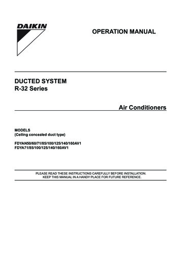
DIMENSIONAL/PHYSICAL DATAFigure 1 R30 C/H Dimensions - Inches (mm)Table 1 Nominal Capacities, Dimensions, Shipping WeightsModelDimensionStraight Cooling Nominal CapacitiesR30 C/Hin. (mm)9,00012,00015,000BtuhA30.60 (777.2)2.63.54.4kWB17.04 (432.7)C22.04 (559.8)D3.85 (97.9)E12.95 (329)F30.60 (777.2)G30.88 (784.2)H10.14 (257.6)I5.75 (146.1)J16.25 (412.8)Heat Pump Nominal Capacities9,00012,00015,000Btuh2.63.54.4kWTable 2 R30 C/H Performance DataModelR30CoolingBtuh (kW)SensibleHeatEERRatioR 30 C 099,000 (2.6)0.709.0R 30 H 099,000 (2.6)0.709.0R 30 C 1211,200 (3.3)0.688.4R 30 H 1211,200 (3.3)0.688.4R 30 C 1514,000 (4.1)0.637.75R 30 H 1513,500 (3.95)0.637.75P/N 240008641, Rev. D [09/20/2011]5HeatPumpCOPBtuh or Air ShippingFlowWeightCFM (L/s)lbs (Kg)N/A 375 (177)2.67 375 (177)N/A 400 (189)2.6400 (189)140 (64)N/A 400 (189)2.51 400 (189)Made in USA
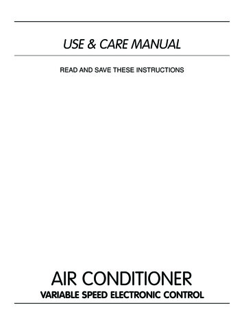
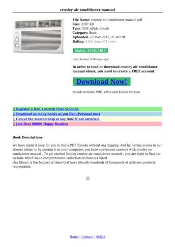
GENERAL PRODUCT INFORMATIONFigure 2 R30C R0H chassisFanCycleSwitch(FCS)Unit O/NC SwitchValve OrientationSwitch (VOS)Fresh AirSwitch(FAS)RemoteTerminal BlockThe Right Fit for Comfort6P/N 240008641, Rev. D [09/20/2011]
GENERAL PRODUCT INFORMATION (CONTINUED)Product DescriptionCondensate Removal The outdoor fan incorporates condensate slinger ring —Condensate is thrown onto the coil, where it evaporates,improving system performance.RetroAire Replacement Packaged Terminal Air Condition/Heat Pumps units are available in straight cooling (PTAC)or as heat pump systems (PTHP). Both the PTAC and PTHPconfigurations fit the wall sleeves of the units listed on thefront cover. Heat pumps (PTHP) reduce energy costs andwill operate in mechanical heat mode down to anoutdoor temperature of 40 F (4.4 C), Below 40 F(4.4 C) heating is accomplished by an auxillaryheat option.Retroaire PTAC/PTHP units: Use R-410A refrigerant. This refrigerant is not affectedby a phase out schedule. Thermostatic drain pan valve for condensate eliminationwhen outdoor temperature drops below 60 F (15 C)(heat pump units only).Controls Unit-mounted operating controls include thermostat, fanspeed control, heat/cool switch, fan cycle switch, freshair switch (if equipped) Ability to utilize 1-stage or 2-stage thermostat. 2 stagethermostat is capable of activating emergency heat if anauxiliary heat source is available. Include high-efficiency rotary compressors, protected bya 5-year warranty. Low ambient protection — see "Microprocessor controlboard" for details. Include an enhanced, high-efficiency heat exchangers. Offer two fan speeds. Ability to control a normally-open or normally-closedmotor valve switch (on hydronic heat units only). Valvecontrols must be ordered for 24V or line voltage. Incorporate positive condensate re-evaporation toimprove efficiency. All hydronic heat units include molex plugs forconnection of hydronic valve motor. Have an optional motorized fresh-air feature with apositive pressure seal.RetroAire PTAC/PTHP ratings meet or exceed ASHRAE90.1 Standards for energy efficiency: Remote mount controls include fan speed control andfresh air switch (if equipped) All units are equipped with manual reset high pressureswitch which prevents abnormal high pressureoperation, increasing compressor reliability. PTAC/PTHP units are available in nominal sizes of9,000 Btuh, (2.6kW) 12,000 Btuh (3.5kW) or15,000 Btuh (4.4kW).Microprocessor Control Board The universal control board is used in straight cooling,electric resistance heat, hydronic heat, or cooling/heatpump applications. PTAC units (straight cooling only) are also available at18,000 Btuh (5.3kW). Energy Efficiency Rating (EER) as high as 10. Coefficient of performance (COP) ratings as high as 2.90for heat pumps. Random start timer prevents multiple units fromsimultaneous startups after power interruption or oninitial power-up.Standard Controls And Components Fan purge — fan remains on for 60 seconds after heat/cool is satisfied.Construction 20-gauge galvanized steel construction of chassis. Anti-short-cycle compressor protection prevents thecompressor from rapid cycling, increases compressorreliability. Condenser baffle options to accommodate extended wallsleeve applications. (Consult the factory for special orderitems). Freeze-protection prevents evaporator coil freeze up,improving compressor reliability. Powder-coated condenser and evaporator drain pan. Low ambient lockout prevents compressor operationin outdoor temperatures less than 40 F (4.4 C). (OnPTHP units supplied with unit-mounted control, thecontrol causes automatic changeover to auxiliary heat, ifinstalled.) Foam strip seal for supply air duct. Weather strip insulation.Air Systems Motors are thermally-protected PSC type. Test operation — all timers are temporarily suppressedto allow ease of testing or troubleshooting. Air-stream surfaces are insulated with 1/4" fiber-glass or1/8" (3.2 mm) Volara . Control board LED provides self-diagnostictroubleshooting codes, see "Sequence of operation." The indoor fan is a foward-curved type, directlymounted to the motor shaft. Unit mount controls include a field selection switch tocontrol indoor fan by either cycling with compressoroperation or continuously with the unit.P/N 240008641, Rev. D [09/20/2011]7Made in USA
GENERAL PRODUCT INFORMATION (CONTINUED)Factory-Installed Options (Consult TheFactory) 265/277V(12 and 15 only) 115V (09 &12 Models Only) Corrosion-resistant coil option — used for seacoastand harsh-environment usage; coated aluminumfin/copper tube condenser coil. Motorized fresh-air damper Supplemental electric heat — see heat options on “Modelcoding” on page 9. Hydronic heat controls Front air intakeField-Installed Accessories Hydronic heat — the coil assembly is shipped loose forfield installation. Remote wall thermostat — digital 1-stage or 2-stageavailable. Wall sleeves, louvers, and cabinets Aquastat - delays fan start-up until coil reaches 100 F(38 C) to virtually eliminate "cold" blow condition. Hydronic control valve , Water 2 way & 3 way Hydronic control valve, Steam 2 way Hydronic Isolation valve, 1/2 in Sweat Connection.The Right Fit for Comfort8P/N 240008641, Rev. D [09/20/2011]
PTAC/PTHP MODEL CODINGFigure 3 Model codingPosition number:Chassis coding[verify with rating plate]123456789101112131415RProduct SeriesCompressor CodesR C - Straight Cool Unit - 30[ A TECH ] *[ L LG ][ T TOSHIBA ] *R H - Heat Pump Unit -30Standard/Special[ 0 standard ][ A-Z special option ]Cooling Capacity[ 09 9,000 Btuh ][ 12 12,000 Btuh][ 15 15,000 Btuh]Design Revision[ A revision level ]Open Options[ A standard][ C Coated Coil ]VoltageA 115 V / 1 / 60 ] (Models 9 & 12 BTU only)D 208/230 V / 1 / 60 ][ E 265/277 V / 1 / 60 ][[Open Options[ A standard]Heat Options[ 0 no electric heat ][ 2 2 KW electric heat ][ 3 3 KW electric heat ][ 4 4 KW electric heat ][ 5 5 KW electric heat ]Control Options[ 0 (UM) unit-mount with elec. heat or no elec. heat ]Air Options[ 1 (RMT) remote tstat with elec. heat or no elec. heat ][ A no fresh air damper ][ 2 (UM) unit-mount hyd. heat N/O or N/C valve (line volt.) ] [ B with fresh air damper ][ 3 (RMT) remote tstat hyd. heat N/O or N/C valve (line volt.) ][ 4 (UM) unit-mount hyd. heat N/O or N/C valve (24 volt.) ][ 5 (RMT) remote tstat hyd. heat N/O or N/C valve (24 volt.) ]* Compressor subject to Manufacture AvailabilityField Installed Accessories[items to be selected during the ordering process]Sea Coast Coated Coils (Factory Installed, consultfactory)Remote thermostatHydronic HeatWall Sleeves. Louvers, & Cabinet (Consult Factory)P/N 240008641, Rev. D [09/20/2011]9Made in USA
FEATURESIndoor Coil Freeze Protection (Standard)Anti-Short Cycle Timer (Standard)This feature will prevent the indoor coil from freeze up inthe cooling mode. Indoor coil freeze up can occur due to a dirty air filter,restricted or poor air flow, low refrigerant charge or lowroom or outdoor temperatures.The microprocessor control uses this timing to preventshort-cycling of the compressor. When the compressor cycles off on a heating or coolingcall, the controller starts a 180-second timer. The compressor will not be allowed to start until thistime has elapsed. On initial power-up or after a power failure, this timingoccurs after the random start timing. This in turn can cause compressor damage. Should a freeze condition be detected, the compressorand outdoor fan will be switched off for a minimum ofthree minutes until the freeze condition is satisfied. During this time the indoor fan will continue to run toaid in the defrost process.Condensate Removal (Standard)The RetroAire replacement unit (cooling operation) isdesigned to eliminate condensate by slinging it onto theoutdoor coil. Condensate drains through the bulkhead to the areanear the outdoor fan. As part of its normal operation, the unit will producecondensate and collect it in the base pan of the unit.There it is picked up by the outdoor fan slinger ringand deposited onto the condenser coil. During thecooling season, this improves the unit’s efficiency bymaintaining reduced refrigeration system pressures. Base pan has overflow notches, if too much condensateis produced notches allow condensate to flow out of thebasepan and into the wallsleeve out of the building.Thermostatic Drain Pan Valve (Standard OnHeat Pump Units)On heat pump models (PTHP), condensate can accumulatein the outdoor drain pan during the heat pump cycle. PTHP units include a thermostatic drain valve that openswhen outdoor temperatures fall below 60 F (15 C). When the drain valve opens, condensate flows from thedrain pan onto the bottom of the wall sleeve, where itdrains to the outside.Power Cord With Integral Safety Protection(Standard)All PTAC/PTHP units rated 250v or less are equipped with apower cord with integral safety protection as standard. Providing personal shock protection as well as arcingand fire prevention, the device is designed to sense anydamage in the line cord and disconnect power before afire can occur. Tested in accordance with Underwriters Laboratories,the cord set also offers a unique “passive” operation,meaning the unit does not require resetting if mainpower is interrupted.Heat PumpHeat pump units are “Limited Range” and should beequipped with back-up electric resistance or hydronicheat. Limited Range heat pumps are designed to operatewhen outdoor temperatures are between 75 F(24 C) and40 F(4.4 C) and with a maximum indoor temperature of80 F(26.6 C). The unit is equipped with a reversing valvethat is energized for cooling and de-energized in heatingmode. Electric heating or hydronic heat will operate usingthe onboard control logic below the operating conditions ofthe heat pump.Hydronic Heating (Optional)An optional hydronic heat package may be selected in lieuof electric heat. Heating operation is essentially the sameas that of units with electric heat. This keeps the base pan free of condensate water,which could otherwise freeze during colder outdoortemperatures.Random Start Feature (Standard) The randomstart feature is initiated on initial power-up or after a powerinterruption. The controller adds a random time delay (from 5–120seconds) on start-up, preventing the compressor fromstarting. This staggers the starting of multiple units in a singlefacility, preventing a large surge that might occur if allunits started at the same time.The Right Fit for Comfort10P/N 240008641, Rev. D [09/20/2011]
FEATURESAquastat Connection (Optional)Selecting A Thermostat (By Others)All replacement PTAC/PTHP's with hydronic heat are supplied with a standard line volt Aquastat connection. Thefield installed Aquastat delays the fan operation until thehydronic coil reaches a temperature of 100 F (38 C).When selecting a thermostat other than one offered byEMI, choose a single stage heat/cool, 24v thermostat.Straight cooling with electric heat or hydronic heat (R10C— PTAC's)Select a thermostat that is compatible with a cooling/electric heat system.The thermostat should have “R”, “Y”, “W”, "C" and “G”terminals.Motorized Fresh Air Damper (Optional)The optional motorized fresh air damper allows fresh airinto the space to be conditioned. When the Fresh Airswitch is in the "YES" position the damper door is open andallows fresh air into the space. This feature is only availablewhen the indoor fan is on. When the damper door switchis in the "NO" position, the damper door is closed and doesnot allow air in the space.Heat Pump With Electric Heat (R h - Pthps)Select a thermostat that is compatible with a cooling/single-stage heat/heat pump system.The thermostat should have "R", "Y", "O" and "G" terminals. RetroAireunits are single stage heating only.The eleactric heat and heat pump will not operate simultaneously.Optional Wall-Mounted ThermostatsThermostats Available From EMIEMI offers a thermostat that is compatible with your PTAC/PTHP unit. Select EMI part number 240008208 from the latestRetroAire price list for this option. This is a single stage,cool/heat, thermostat that can be used in all RetroAirecooling, heating or heat pump applications. The thermostat has an adjustable setpoint range ofbetween 45 F(7 C) and 90 F(32 C). For heat pumps another option is EMI part number240008209. This is a 2 stage heat/cool thermostatwhich allows for emergency heat.P/N 240008641, Rev. D [09/20/2011]11Made in USA
PREPARING FOR THE INSTALLATION OF THE PTAC/PTHPElectrical Power ConnectionWARNINGMoving parts can cause personal injury. Avoid contactwith moving parts when testing or servicing the unit.Verify existing wall sleeve/enclosure:RetroAire replacement PTAC/PTHP's are to be usedwith metal wall sleeves.The existing front panels must be secured by screwsthat prevent contact with all parts.Minor dimensions of openings must not exceed ½ inch(12.5mm).The indoor air discharge grill must have dimensionsnot less than 26” x 4”. The grill must separate thetop surface of the chassis from the top surface of thedischarge grill by a minimum of 1 in (25.4mm).1. Check the RetroAire unit rating plate for circuitampacity and required breaker or fuse size.2. Verify that the existing breaker or fuse is thecorrect size.a. Replace the breaker or fuse if incorrectly-sized.b. Breakers must be type HACR only.3. Cord-connected units — verify that the walloutlet is the correct rating. The outlet's bladeconfiguration must match that of the cord suppliedwith the RetroAire unit.4. Hard-wired units — verify that the power wiring iscorrectly sized. Inspect the existing wiring for anydeficiencies, such as cuts or frayed wires. Replacesuch wiring if found.Remove The Old ChassisFor all models, the outdoor openings must preventcontact of all moving parts by means of louversor grills, with minor dimension not exceeding 1 in(25.4mm).Electrical supplyEach unit must have a separate branch circuitprotected by a fuse or breaker. Refer to the unit ratingplate for the proper wire and breaker or fuse size. Useof extension cords is prohibited.1. Disconnect power or unplug cord beforeproceeding.2. Remove the front of the existing room enclosure toexpose the old chassis.3. Loosen any tie-down bolts or screws and removethe old chassis.NOTICEDO NOT connect the RetroAire unit to a circuit with anincorrectly-sized overcurrent-protection device.Dispose of the old chassis following existingstate and federal regulations.All cord-connected 265-volt units must be plugged intoreceptacles within the unit subbase or chassis.4. Inspect the wall sleeve/cabinet for any rust, holes,or damage.a. Clean the wall sleeve of any dirt.b. Repair any damage.c. Ensure proper drainage of condensate or rainwaterto exterior of building.Electrical shock hazard — Before opening the existingunit:Open the power supply disconnect switch. Secure itin an open position during installation. Attach a signstating, "DO NOT TURN ON."On a plug and receptacle connection, unplug theexisting unit at the wall outlet. DO NOT plug in thenew unit until installation is complete and the start-upchecklist has been completed.Failure to comply with the above could result in severepersonal injury, death or substantial property damage.NOTICEAll wiring should be in accordance with both the National ElectricCode (NEC) and the local building codes.UNITS RATED 208/230V — the RetroAire unit is wired for 230vprimary voltage from the factory. The transformer must be rewiredby the installer if the jobsite voltage is 208v. Change the transformertap from orange to red. See the wiring diagram for details.The Right Fit for Comfort125. Remove or repair the old weather seals and makenote of the location for the installation of any newseals.6. Check the wall sleeve/cabinet to ensure all drainholes are open and that:a. The wall sleeve/enclosure is level left to rightb. The back is pitched to the outside by ½in(12.5mm) maximum.7. Before installing the new chassis, inspect theoutdoor louver for a minimum free area of 70%and remove any obstructions. Obstructions willrestrict air flow over the condenser coil and maycause serious damage to the chassis. It will alsovoid the warranty.8. See the instructions for the specific RetroAire uniton the following pages.9. DO NOT connect power to the unit or plug in thecord until all instructions in this manual have beenfollowed.P/N 240008641, Rev. D [09/20/2011]
INSTALLATION INSTRUCTIONS — R30C R30HInstallation5. Hard-wired units — If the unit is hard wired, followthe instructions on page 12 to verify existing wiringand overcurrent protection. Remove the line cordwires from the PTAC/PTHP power entrance terminals.Route the power supply wiring through a strain-reliefbushing and connect leads to the power entranceterminals. Secure the strain-relief clamp. (If wiringis through conduit, insert the conduit through thecontrol box knockout and secure in place.) DO NOTturn on power until completing instructions in "FinalInspection and Startup" on page.1. Verify existing wall thickness — The distancefrom the condenser coil to the outdoor louvervaries with wall sleeve depth. Units are shippedwith baffles factory installed. Other air bafflekits are available from the factory (unique forapplications). Have the wall sleeve depth readywhen ordering to ensure proper baffle size.2. Connecting optional hydronic coil controls— If the hydronic heat option has been ordered,then the hydronic coil will need to be field installedon the new unit. The coil with the old unit canbe located in the subbase, under the chassis ina special attachment, or above the chassis in aspecial attachment. It is necessary to know wherethe coil is to be located and the physical size ofthe coil so the new coil can be verified if orderedfor replacement. The new coil should be installedin the same manner as the coil it is replacing.Hydronic coils are not factory installed and need tobe ordered.6. DO NOT PLUG IN the line cord, if used. Followinstructions in "Final Inspection and Startup".Figure 5 R30C H chassis and installation kitcontents – Remove the 2-position connector assembly fromkit bag supplied with unit (this will have 2 yellowwires attached). – Splice to yellow wires to valve motor using 2 crimp popcorn.– Connect this 2-position connector to the 2-positionconnection located on the bottom of the controlbox panel.3. Connecting accessory Aquastat — If the accessoryAquastat has been ordered then it will need to befield installed.– Remove the black jumper wire located on thebottom panel of the control box (this is alsoterminated with a 2-position connector).– Cut the jumper wire in the middle and splicethe Aquastat to the jumper using 2 - crimppopcorns.– Place the connector back into original location.Refer to the wiring diagram on the unit fordetails. Figure 4 R30C H chassis and installation kitcontents4. Secure chassis — After ensuring that all seals arethe correct size and in the proper location, and thecorrect baffles are attached to the condenser coilin the proper orientation, slide the unit into finalposition and tighten any tie down bolts or screwsas necessary.BafflesP/N 240008641, Rev. D [09/20/2011]13Made in USA
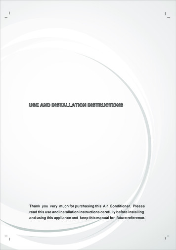
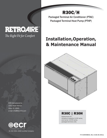
SEQUENCE OF OPERATIONThe following Sequence of Operation applies toPTAC/PTHP units.TroubleCode(Blinks)12345The R C units are straight cool, single stage airconditioners available with electric or hydronic heat.The R H units are limited range, single stage heatpump. Mechanical compression heating (heat pumpmode) is locked out at outdoor temperatures of approximately 35 ºF (1.7 ºC) and below. Below theseambient temperatures, the auxiliary electric or hydronic heat will be used.GeneralThe unit is controlled by a microprocessor. Thermostat and control connections are made to the controlboard.Figure 6Normal OperationAnti-Short Cycle Timer ActiveOutdoor Coil Freeze ProtectionIndoor Coil Freeze ProtectionSimultaneous “Y” and “W” CallInitial Power-Up or Power RestorationWhen power is applied to the unit, either for the first timeor after a power failure, the board will initialize itself.During the initialization, LED1 will be lit continuously forapproximately 5 seconds. Following the initialization, arandom start timer is initiated. This timer adds a randomlyselected 5-120 seconds to the start-up sequence, reducingthe possibility of multiple units starting at the same time.Once the random start timer has expired, a 180 secondAnti-Short Cycle Timer is initiated and the Processor BoardTrouble Code LED is set to blink a 2 flash code. This timerprevents the compressor from rapid cycling. After theAnti-Short Cycle Timer expires, the Processor Board TroubleCode LED is set to blink a 1 blink Trouble Code, indicatingnormal operation.- Control BoardTESTConfig.JumperR C / R H; Cooling OperationLEDIndicatorLight( For unit mount controls)HeatPumpConfig.JumperTwo configuration jumpers are located on theboard, see Figure 8. The Heat Pump ConfigurationJumper is a 3 pin jumper. Straight Cool units R C, the jumper should belocated on the outside two pins. Heat Pump units R H, the jumper should be located on the inside two pins.A second configuration jumper “TEST” allows for thecontrol’s internal timers to be by-passed for test purposes. Placing the jumper on the two pins enables thetest mode.A status LED (Light Emitting Diode), LED1 is located onthe center of the board. A series of blinks communicatesthe status of the board. Between the blink sequence isa separation of approximately 2 seconds. The StatusCode is listed below.The Right Fit for ComfortStatus14With the System Switch [SS] set to “Cool”, and the FanCycle Switch [FCS] set to “On” (Continuous Fan Operation), the indoor fan motor will start. If the Fan CycleSwitch [FCS] is set to “Off” (Cycling Fan Operation), theindoor fan motor will start with a call for cooling from theinternal thermostat [T’stat]. If the unit is equipped with aMotorized Fresh Air Damper, and is active with the FreshAir Switch [FAS], the damper will open with a call for theindoor fan. If the room temperature is below the thermostat setting the fan operation will continue as noted above.If the room temperature is above the thermostat setting,the reversing valve will be energized, the compressor andoutdoor fan will start provided the Anti-Short Cycle Timerhas timed out from the initial power-up, power restorationor a previous compressor on cycle. Operation will continue until the room temperature satisfies the thermostat.Once the room temperature falls below the set point by 3ºF (2 ºC), the compressor, outdoor fan mot
Packaged Terminal Air Conditioner (PTAC) Packaged Terminal Heat Pump (PTHP) Installation,Operation, & Maintenance Manual R30C R30H Replacement for: ZoneAire & Keeprite C/CHP series, and Carrier 51P/PH series packaged terminal units. To the installer Retain this manual and warranty for future reference. Before leaving the premises, review this manual to be sure the unit has been installed .