Transcription
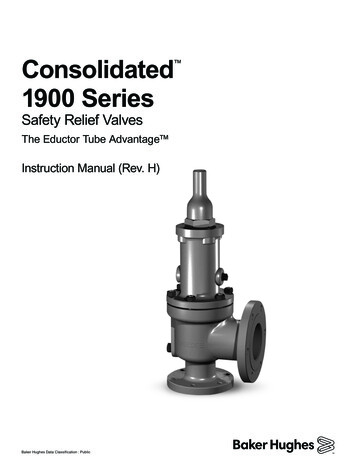
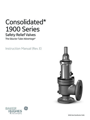
Consolidated*1900 SeriesSafety Relief ValvesThe Eductor Tube Advantage*Instruction Manual (Rev. E)BHGE Data Classification: Public
THESE INSTRUCTIONS PROVIDE THE CUSTOMER/OPERATOR WITH IMPORTANT PROJECT-SPECIFIC REFERENCEINFORMATION IN ADDITION TO THE CUSTOMER/OPERATOR’S NORMAL OPERATION AND MAINTENANCEPROCEDURES. SINCE OPERATION AND MAINTENANCE PHILOSOPHIES VARY, BHGE (BAKER HUGHES, A GE COMPANYAND ITS SUBSIDIARIES AND AFFILIATES) DOES NOT ATTEMPT TO DICTATE SPECIFIC PROCEDURES, BUT TO PROVIDEBASIC LIMITATIONS AND REQUIREMENTS CREATED BY THE TYPE OF EQUIPw xMENT PROVIDED.THESE INSTRUCTIONS ASSUME THAT OPERATORS ALREADY HAVE A GENERAL UNDERSTANDING OF THEREQUIREMENTS FOR SAFE OPERATION OF MECHANICAL AND ELECTRICAL EQUIPMENT IN POTENTIALLY HAZARDOUSENVIRONMENTS. THEREFORE, THESE INSTRUCTIONS SHOULD BE INTERPRETED AND APPLIED IN CONJUNCTIONWITH THE SAFETY RULES AND REGULATIONS APPLICABLE AT THE SITE AND THE PARTICULAR REQUIREMENTS FOROPERATION OF OTHER EQUIPMENT AT THE SITE.THESE INSTRUCTIONS DO NOT PURPORT TO COVER ALL DETAILS OR VARIATIONS IN EQUIPMENT NOR TOPROVIDE FOR EVERY POSSIBLE CONTINGENCY TO BE MET IN CONNECTION WITH INSTALLATION, OPERATION ORMAINTENANCE. SHOULD FURTHER INFORMATION BE DESIRED OR SHOULD PARTICULAR PROBLEMS ARISE WHICHARE NOT COVERED SUFFICIENTLY FOR THE CUSTOMER/OPERATOR'S PURPOSES THE MATTER SHOULD BE REFERREDTO BHGE.THE RIGHTS, OBLIGATIONS AND LIABILITIES OF BHGE AND THE CUSTOMER/OPERATOR ARE STRICTLY LIMITED TOTHOSE EXPRESSLY PROVIDED IN THE CONTRACT RELATING TO THE SUPPLY OF THE EQUIPMENT. NO ADDITIONALREPRESENTATIONS OR WARRANTIES BY BHGE REGARDING THE EQUIPMENT OR ITS USE ARE GIVEN OR IMPLIED BYTHE ISSUE OF THESE INSTRUCTIONS.THESE INSTRUCTIONS ARE FURNISHED TO THE CUSTOMER/OPERATOR SOLELY TO ASSIST IN THE INSTALLATION,TESTING, OPERATION, AND/OR MAINTENANCE OF THE EQUIPMENT DESCRIBED. THIS DOCUMENT SHALL NOT BEREPRODUCED IN WHOLE OR IN PART WITHOUT THE WRITTEN APPROVAL OF BHGE.2 BHGE 2018 Baker Hughes, a GE company. All rights reserved.
Conversion TableAll the United States Customary System (USCS) values are convertedto metric values using the following conversion factors:USCS UnitConversion FactorMetric rpsig0.06894757bargft lb1.3558181Nm F5/9 ( F-32) CNote: Multiply USCS value with conversion factor to get metric value.NOTICE!For valve configurations not listed in thismanual, please contact your local Green Tag*Center for assistance. 2018 Baker Hughes, a GE company. All rights reserved.Consolidated 1900 Series SRV Instruction Manual 3
ContentsI.II.Product Safety Sign and Label System. . . . . . . . . . . . . . . . . . . . . . . . . . . . . . . . . . . . . . . . . . . . . . . . . . . . 6Safety Alerts. . . . . . . . . . . . . . . . . . . . . . . . . . . . . . . . . . . . . . . . . . . . . . . . . . . . . . . . . . . . . . . . . . . . . . . . . . . . . 7Read - U nderstand - Practice. . . . . . . . . . . . . . . . . . . . . . . . . . . . . . . . . . . . . . . . . . . . . . . . . . . . . . . . . . . . . . . . . . . . . . . . . . . . . . . 7III.IV.V.VI.Safety Notice. . . . . . . . . . . . . . . . . . . . . . . . . . . . . . . . . . . . . . . . . . . . . . . . . . . . . . . . . . . . . . . . . . . . . . . . . . . . 8Warranty Information. . . . . . . . . . . . . . . . . . . . . . . . . . . . . . . . . . . . . . . . . . . . . . . . . . . . . . . . . . . . . . . . . . . . 9Terminology for Safety Relief Valves . . . . . . . . . . . . . . . . . . . . . . . . . . . . . . . . . . . . . . . . . . . . . . . . . . . . . 10Handling and Storage. . . . . . . . . . . . . . . . . . . . . . . . . . . . . . . . . . . . . . . . . . . . . . . . . . . . . . . . . . . . . . . . . . . . 11Handling. . . . . . . . . . . . . . . . . . . . . . . . . . . . . . . . . . . . . . . . . . . . . . . . . . . . . . . . . . . . . . . . . . . . . . . . . . . . . . . . . . . . . . . . . . . . . . . . . . 11Storage. . . . . . . . . . . . . . . . . . . . . . . . . . . . . . . . . . . . . . . . . . . . . . . . . . . . . . . . . . . . . . . . . . . . . . . . . . . . . . . . . . . . . . . . . . . . . . . . . . . 11VII.VIII.Pre-Installation and Installation Instructions. . . . . . . . . . . . . . . . . . . . . . . . . . . . . . . . . . . . . . . . . . . . . 11Design Features and Nomenclature. . . . . . . . . . . . . . . . . . . . . . . . . . . . . . . . . . . . . . . . . . . . . . . . . . . . . . 12Cap and Lever Interchangeability . . . . . . . . . . . . . . . . . . . . . . . . . . . . . . . . . . . . . . . . . . . . . . . . . . . . . . . . . . . . . . . . . . . . . . . . . 12Design Simplicity . . . . . . . . . . . . . . . . . . . . . . . . . . . . . . . . . . . . . . . . . . . . . . . . . . . . . . . . . . . . . . . . . . . . . . . . . . . . . . . . . . . . . . . . . 12Nomenclature Related to Design Features . . . . . . . . . . . . . . . . . . . . . . . . . . . . . . . . . . . . . . . . . . . . . . . . . . . . . . . . . . . . . . . . 12Simple Blowdown Adjustment. . . . . . . . . . . . . . . . . . . . . . . . . . . . . . . . . . . . . . . . . . . . . . . . . . . . . . . . . . . . . . . . . . . . . . . . . . . . 12Valve Interchangeability . . . . . . . . . . . . . . . . . . . . . . . . . . . . . . . . . . . . . . . . . . . . . . . . . . . . . . . . . . . . . . . . . . . . . . . . . . . . . . . . . . 12IX.X.Introduction. . . . . . . . . . . . . . . . . . . . . . . . . . . . . . . . . . . . . . . . . . . . . . . . . . . . . . . . . . . . . . . . . . . . . . . . . . . . 12Consolidated 1900 Series Safety Relief Valve. . . . . . . . . . . . . . . . . . . . . . . . . . . . . . . . . . . . . . . . . . . . . 13A.B.C.D.E.XI.Metal Seat Valve. . . . . . . . . . . . . . . . . . . . . . . . . . . . . . . . . . . . . . . . . . . . . . . . . . . . . . . . . . . . . . . . . . . . . . . . . . . . . . . . . . . . . . 13Standard Cap Types . . . . . . . . . . . . . . . . . . . . . . . . . . . . . . . . . . . . . . . . . . . . . . . . . . . . . . . . . . . . . . . . . . . . . . . . . . . . . . . . . . 14Bellows Metal Seat Valve. . . . . . . . . . . . . . . . . . . . . . . . . . . . . . . . . . . . . . . . . . . . . . . . . . . . . . . . . . . . . . . . . . . . . . . . . . . . . . 15V-W Bellows Metal Seat Valve. . . . . . . . . . . . . . . . . . . . . . . . . . . . . . . . . . . . . . . . . . . . . . . . . . . . . . . . . . . . . . . . . . . . . . . . . 16Soft Seat Valve. . . . . . . . . . . . . . . . . . . . . . . . . . . . . . . . . . . . . . . . . . . . . . . . . . . . . . . . . . . . . . . . . . . . . . . . . . . . . . . . . . . . . . . . 17Recommended Installation Practices . . . . . . . . . . . . . . . . . . . . . . . . . . . . . . . . . . . . . . . . . . . . . . . . . . . . 18A. Mounting Position. . . . . . . . . . . . . . . . . . . . . . . . . . . . . . . . . . . . . . . . . . . . . . . . . . . . . . . . . . . . . . . . . . . . . . . . . . . . . . . . . . . . . 18B. Inlet Piping. . . . . . . . . . . . . . . . . . . . . . . . . . . . . . . . . . . . . . . . . . . . . . . . . . . . . . . . . . . . . . . . . . . . . . . . . . . . . . . . . . . . . . . . . . . . 18C. Outlet Piping. . . . . . . . . . . . . . . . . . . . . . . . . . . . . . . . . . . . . . . . . . . . . . . . . . . . . . . . . . . . . . . . . . . . . . . . . . . . . . . . . . . . . . . . . . 19XII.Disassembly of 1900 Series Safety Relief Valves. . . . . . . . . . . . . . . . . . . . . . . . . . . . . . . . . . . . . . . . . . 20A. General Information . . . . . . . . . . . . . . . . . . . . . . . . . . . . . . . . . . . . . . . . . . . . . . . . . . . . . . . . . . . . . . . . . . . . . . . . . . . . . . . . . . 20B. SRV Disassembly. . . . . . . . . . . . . . . . . . . . . . . . . . . . . . . . . . . . . . . . . . . . . . . . . . . . . . . . . . . . . . . . . . . . . . . . . . . . . . . . . . . . . . 20C. Cleaning. . . . . . . . . . . . . . . . . . . . . . . . . . . . . . . . . . . . . . . . . . . . . . . . . . . . . . . . . . . . . . . . . . . . . . . . . . . . . . . . . . . . . . . . . . . . . . 23XIII.Maintenance Instructions. . . . . . . . . . . . . . . . . . . . . . . . . . . . . . . . . . . . . . . . . . . . . . . . . . . . . . . . . . . . . . . 24A.B.C.D.E.F.H.I.J.K.L.M.4 BHGEGeneral Information . . . . . . . . . . . . . . . . . . . . . . . . . . . . . . . . . . . . . . . . . . . . . . . . . . . . . . . . . . . . . . . . . . . . . . . . . . . . . . . . . . 24Lapping Nozzle Seats (Non-O-Ring Styles). . . . . . . . . . . . . . . . . . . . . . . . . . . . . . . . . . . . . . . . . . . . . . . . . . . . . . . . . . . . . 24Lapped Nozzle Seat Widths . . . . . . . . . . . . . . . . . . . . . . . . . . . . . . . . . . . . . . . . . . . . . . . . . . . . . . . . . . . . . . . . . . . . . . . . . . . 25Lapping Disc Seats. . . . . . . . . . . . . . . . . . . . . . . . . . . . . . . . . . . . . . . . . . . . . . . . . . . . . . . . . . . . . . . . . . . . . . . . . . . . . . . . . . . . 27Precautions and Hints for Lapping Seats. . . . . . . . . . . . . . . . . . . . . . . . . . . . . . . . . . . . . . . . . . . . . . . . . . . . . . . . . . . . . . . 27Lapping O-Ring Seating Surfaces. . . . . . . . . . . . . . . . . . . . . . . . . . . . . . . . . . . . . . . . . . . . . . . . . . . . . . . . . . . . . . . . . . . . . . 28Re-Machining Nozzle Seats and Bores. . . . . . . . . . . . . . . . . . . . . . . . . . . . . . . . . . . . . . . . . . . . . . . . . . . . . . . . . . . . . . . . . 28Re-Machining the Disc Seat . . . . . . . . . . . . . . . . . . . . . . . . . . . . . . . . . . . . . . . . . . . . . . . . . . . . . . . . . . . . . . . . . . . . . . . . . . . 29Checking Spindle Concentricity. . . . . . . . . . . . . . . . . . . . . . . . . . . . . . . . . . . . . . . . . . . . . . . . . . . . . . . . . . . . . . . . . . . . . . . . 29Set Pressure Change-Disc Holder. . . . . . . . . . . . . . . . . . . . . . . . . . . . . . . . . . . . . . . . . . . . . . . . . . . . . . . . . . . . . . . . . . . . . . 30Checking Lift on Restricted Lift Valves. . . . . . . . . . . . . . . . . . . . . . . . . . . . . . . . . . . . . . . . . . . . . . . . . . . . . . . . . . . . . . . . . 30Determining the Correct Limit Washer Length. . . . . . . . . . . . . . . . . . . . . . . . . . . . . . . . . . . . . . . . . . . . . . . . . . . . . . . . . 32 2018 Baker Hughes, a GE company. All rights reserved.
XIV.Inspection and Part Replacement. . . . . . . . . . . . . . . . . . . . . . . . . . . . . . . . . . . . . . . . . . . . . . . . . . . . . . . . 34A.B.C.D.E.F.G.H.I.XV.Reassembly of 1900 Series SRV. . . . . . . . . . . . . . . . . . . . . . . . . . . . . . . . . . . . . . . . . . . . . . . . . . . . . . . . . . 44A.B.C.D.XVI.Nozzle Inspection Criteria. . . . . . . . . . . . . . . . . . . . . . . . . . . . . . . . . . . . . . . . . . . . . . . . . . . . . . . . . . . . . . . . . . . . . . . . . . . . . 34Nozzle Seat Width. . . . . . . . . . . . . . . . . . . . . . . . . . . . . . . . . . . . . . . . . . . . . . . . . . . . . . . . . . . . . . . . . . . . . . . . . . . . . . . . . . . . 34Nozzle Bore Inspection. . . . . . . . . . . . . . . . . . . . . . . . . . . . . . . . . . . . . . . . . . . . . . . . . . . . . . . . . . . . . . . . . . . . . . . . . . . . . . . . 341900 Series SRV Standard Disc Inspection Areas . . . . . . . . . . . . . . . . . . . . . . . . . . . . . . . . . . . . . . . . . . . . . . . . . . . . . . 341900 Series Thermodisc* Replacement Criteria. . . . . . . . . . . . . . . . . . . . . . . . . . . . . . . . . . . . . . . . . . . . . . . . . . . . . . . . 34Disc Holder Inspection Criteria. . . . . . . . . . . . . . . . . . . . . . . . . . . . . . . . . . . . . . . . . . . . . . . . . . . . . . . . . . . . . . . . . . . . . . . . 39Guide Inspection Criteria. . . . . . . . . . . . . . . . . . . . . . . . . . . . . . . . . . . . . . . . . . . . . . . . . . . . . . . . . . . . . . . . . . . . . . . . . . . . . . 42Spindle Inspection Criteria. . . . . . . . . . . . . . . . . . . . . . . . . . . . . . . . . . . . . . . . . . . . . . . . . . . . . . . . . . . . . . . . . . . . . . . . . . . . 42Spring Inspection Criteria. . . . . . . . . . . . . . . . . . . . . . . . . . . . . . . . . . . . . . . . . . . . . . . . . . . . . . . . . . . . . . . . . . . . . . . . . . . . . 43General Information . . . . . . . . . . . . . . . . . . . . . . . . . . . . . . . . . . . . . . . . . . . . . . . . . . . . . . . . . . . . . . . . . . . . . . . . . . . . . . . . . . 44Preparation. . . . . . . . . . . . . . . . . . . . . . . . . . . . . . . . . . . . . . . . . . . . . . . . . . . . . . . . . . . . . . . . . . . . . . . . . . . . . . . . . . . . . . . . . . . 44Lubrication. . . . . . . . . . . . . . . . . . . . . . . . . . . . . . . . . . . . . . . . . . . . . . . . . . . . . . . . . . . . . . . . . . . . . . . . . . . . . . . . . . . . . . . . . . . . 44Reassembly Procedure. . . . . . . . . . . . . . . . . . . . . . . . . . . . . . . . . . . . . . . . . . . . . . . . . . . . . . . . . . . . . . . . . . . . . . . . . . . . . . . . 44Setting and Testing. . . . . . . . . . . . . . . . . . . . . . . . . . . . . . . . . . . . . . . . . . . . . . . . . . . . . . . . . . . . . . . . . . . . . . 51A.B.C.D.E.F.G.H.I.J.K.General Information . . . . . . . . . . . . . . . . . . . . . . . . . . . . . . . . . . . . . . . . . . . . . . . . . . . . . . . . . . . . . . . . . . . . . . . . . . . . . . . . . . 51Test Equipment. . . . . . . . . . . . . . . . . . . . . . . . . . . . . . . . . . . . . . . . . . . . . . . . . . . . . . . . . . . . . . . . . . . . . . . . . . . . . . . . . . . . . . . 51Test Media. . . . . . . . . . . . . . . . . . . . . . . . . . . . . . . . . . . . . . . . . . . . . . . . . . . . . . . . . . . . . . . . . . . . . . . . . . . . . . . . . . . . . . . . . . . . 51Setting the Valve. . . . . . . . . . . . . . . . . . . . . . . . . . . . . . . . . . . . . . . . . . . . . . . . . . . . . . . . . . . . . . . . . . . . . . . . . . . . . . . . . . . . . . 51Set Pressure Compensation. . . . . . . . . . . . . . . . . . . . . . . . . . . . . . . . . . . . . . . . . . . . . . . . . . . . . . . . . . . . . . . . . . . . . . . . . . . 51Setting the Pressure . . . . . . . . . . . . . . . . . . . . . . . . . . . . . . . . . . . . . . . . . . . . . . . . . . . . . . . . . . . . . . . . . . . . . . . . . . . . . . . . . . 53Seat Tightness Testing. . . . . . . . . . . . . . . . . . . . . . . . . . . . . . . . . . . . . . . . . . . . . . . . . . . . . . . . . . . . . . . . . . . . . . . . . . . . . . . . 53Recommended Backpressure Testing for Joint Leakage. . . . . . . . . . . . . . . . . . . . . . . . . . . . . . . . . . . . . . . . . . . . . . . . 55Blowdown Adjustment. . . . . . . . . . . . . . . . . . . . . . . . . . . . . . . . . . . . . . . . . . . . . . . . . . . . . . . . . . . . . . . . . . . . . . . . . . . . . . . . 55Hydrostatic Testing and Gagging. . . . . . . . . . . . . . . . . . . . . . . . . . . . . . . . . . . . . . . . . . . . . . . . . . . . . . . . . . . . . . . . . . . . . . 56Manual Popping of the Valve . . . . . . . . . . . . . . . . . . . . . . . . . . . . . . . . . . . . . . . . . . . . . . . . . . . . . . . . . . . . . . . . . . . . . . . . . . 56XVII. Troubleshooting 1900 Series SRVs. . . . . . . . . . . . . . . . . . . . . . . . . . . . . . . . . . . . . . . . . . . . . . . . . . . . . . . 57XVIII. 1900 Series Safety Relief Valve Options. . . . . . . . . . . . . . . . . . . . . . . . . . . . . . . . . . . . . . . . . . . . . . . . . . 58A.B.C.D.XIX.General Information . . . . . . . . . . . . . . . . . . . . . . . . . . . . . . . . . . . . . . . . . . . . . . . . . . . . . . . . . . . . . . . . . . . . . . . . . . . . . . . . . . 58Conversion from Conventional to Bellows Type. . . . . . . . . . . . . . . . . . . . . . . . . . . . . . . . . . . . . . . . . . . . . . . . . . . . . . . . 58Conversion from Bellows to Conventional Type. . . . . . . . . . . . . . . . . . . . . . . . . . . . . . . . . . . . . . . . . . . . . . . . . . . . . . . . 60Optional Glide-Aloy Parts. . . . . . . . . . . . . . . . . . . . . . . . . . . . . . . . . . . . . . . . . . . . . . . . . . . . . . . . . . . . . . . . . . . . . . . . . . . . 61Maintenance Tools and Supplies. . . . . . . . . . . . . . . . . . . . . . . . . . . . . . . . . . . . . . . . . . . . . . . . . . . . . . . . . 62A. Lapping Tools . . . . . . . . . . . . . . . . . . . . . . . . . . . . . . . . . . . . . . . . . . . . . . . . . . . . . . . . . . . . . . . . . . . . . . . . . . . . . . . . . . . . . . . . . 63XX.Replacement Parts Planning. . . . . . . . . . . . . . . . . . . . . . . . . . . . . . . . . . . . . . . . . . . . . . . . . . . . . . . . . . . . . 64A. Basic Guidelines . . . . . . . . . . . . . . . . . . . . . . . . . . . . . . . . . . . . . . . . . . . . . . . . . . . . . . . . . . . . . . . . . . . . . . . . . . . . . . . . . . . . . . 64B. Replacement Parts List. . . . . . . . . . . . . . . . . . . . . . . . . . . . . . . . . . . . . . . . . . . . . . . . . . . . . . . . . . . . . . . . . . . . . . . . . . . . . . . .64C. Identification and Ordering Essentials. . . . . . . . . . . . . . . . . . . . . . . . . . . . . . . . . . . . . . . . . . . . . . . . . . . . . . . . . . . . . . . . . 64XXI. Genuine Consolidated Parts. . . . . . . . . . . . . . . . . . . . . . . . . . . . . . . . . . . . . . . . . . . . . . . . . . . . . . . . . . . . . 65XXII. Recommended Spare Parts for 1900 Series SRVs . . . . . . . . . . . . . . . . . . . . . . . . . . . . . . . . . . . . . . . . 66XXIII. Manufacturer’s Field Service, Repair and Training Program. . . . . . . . . . . . . . . . . . . . . . . . . . . . . . . . 68A. Field Service. . . . . . . . . . . . . . . . . . . . . . . . . . . . . . . . . . . . . . . . . . . . . . . . . . . . . . . . . . . . . . . . . . . . . . . . . . . . . . . . . . . . . . . . . . 68B. Factory Repair Facilities. . . . . . . . . . . . . . . . . . . . . . . . . . . . . . . . . . . . . . . . . . . . . . . . . . . . . . . . . . . . . . . . . . . . . . . . . . . . . . . 69C. Maintenance Training . . . . . . . . . . . . . . . . . . . . . . . . . . . . . . . . . . . . . . . . . . . . . . . . . . . . . . . . . . . . . . . . . . . . . . . . . . . . . . . . . 69 2018 Baker Hughes, a GE company. All rights reserved.Consolidated 1900 Series SRV Instruction Manual 5
I.Product Safety Sign and Label SystemIf and when required, appropriate safety labels have been included in therectangular margin blocks throughout this manual. Safety labels are verticallyoriented rectangles as shown in the representative examples (below),consisting of three panels encircled by a narrow border. The panels cancontain four messages which communicate: The level of hazard seriousnessWARNING — Hazards or unsafepractices which COULD result insevere personal injury or death. The consequence of human, or product, interaction with the hazard. The instructions, if necessary, on how to avoid the hazard.The top panel of the format contains a signal word (DANGER, WARNING,CAUTION or ATTENTION) which communicates the level of hazardseriousness.3CAUTION — Hazards or unsafepractices which COULD result inminor personal injury.The center panel contains a pictorial which communicates the natureof the hazard, and the possible consequence of human or productinteraction with the hazard. In some instances of human hazards thepictorial may, instead, depict what preventive measures to take, such aswearing protective equipment.4The bottom panel may contain an instruction message on how to avoid thehazard. In the case of human hazard, this message may also contain a moreprecise definition of the hazard, and the consequences of human interactionwith the hazard, than can be communicated solely by the pictorial.Do not remove boltsif pressure in line, asthis will result in severepersonal injury or death.6 BHGE2Know all valve exhaust/leakage points to avoidpossible severe personalinjury or death.DANGER — Immediate hazardswhich WILL result in severepersonal injury or death.2 The nature of the hazard11ATTENTION — Hazards or unsafepractices which COULD result inproduct or property damage.34Wear necessaryprotective equipment toprevent possible injuryHandle valvecarefully. Do not dropor strike. 2018 Baker Hughes, a GE company. All rights reserved.
II.Safety AlertsRead - Understand - PracticeDanger AlertsA DANGER alert describes actions that may causesevere personal injury or death. In addition, it mayprovide preventive measures to avoid severe personalinjury or death.DANGER alerts are not all-inclusive. BHGE cannotknow all conceivable service methods nor evaluate allpotential hazards. Dangers include: High temperature/pressure can cause injury. Ensureall system pressure is absent before repairing orremoving valves. Do not stand in front of a valve outlet whendischarging. STAND CLEAR OF VALVE to avoidexposure to trapped, corrosive media. Exercise extreme caution when inspecting a pressurerelief valve for leakage. Allow the system to cool to room temperature beforecleaning, servicing, or repairing. Hot components orfluids can cause severe personal injury or death. Always read and comply with safety labels on allcontainers. Do not remove or deface container labels.Improper handling or misuse could result in severepersonal injury or death. Never use pressurized fluids/gas/air to clean clothingor body parts. Never use body parts to check forleaks, flow rates, or areas. Pressurized fluids/gas/air injected into or near the body can cause severepersonal injury or death. Do not work or allow anyone under the influenceof intoxicants or narcotics to work on or aroundpressurized systems. Workers under the influence ofintoxicants or narcotics are a hazard to themselvesand other employees. Actions taken by an intoxicatedemployee can result in severe personal injury ordeath to themselves or others. Always perform correct service and repair. Incorrectservice and repair can result in product or propertydamage or severe personal injury or death. Always use the correct tool for a job. The misuse ofa tool or the use of an improper tool can result inpersonal injury, damage to product or property. Ensure the proper “health physics” procedures arefollowed, if applicable, before starting operation in aradioactive environment.Caution AlertsA CAUTION alert describes actions that may resultin a personal injury. In addition, they may describepreventive measures that must be taken to avoidpersonal injury. Cautions include: Heed all service manual warnings. Read installationinstructions before installing valve(s). Wear hearing protection when testing or operatingvalves. Wear appropriate eye and clothing protection. Wear protective breathing apparatus to protectagainst toxic media. It is the owner’s responsibility to specify and provideprotective wear to protect persons from pressurizedor heated parts. Contact with pressurized or heatedparts can result in severe personal injury or death. 2018 Baker Hughes, a GE company. All rights reserved.Consolidated 1900 Series SRV Instruction Manual 7
III.Safety NoticeProper installation and start-up is essential to the safe and reliable operationof all valve products. The relevant procedures recommended by BHGE, anddescribed in these instructions, are effective methods of performing therequired tasks.It is important to note that these instructions contain various “safetymessages” which should be carefully read in order to minimize the risk ofpersonal injury, or the possibility that improper procedures will be followedwhich may damage the involved BHGE product, or render it unsafe. It is alsoimportant to understand that these “safety messages” are not exhaustive.BHGE can not possibly know, evaluate, and advise any customer of all ofthe conceivable ways in which tasks might be performed, or of the possiblehazardous consequences of each way. Consequently, BHGE has not undertakenany such broad evaluation and, thus, anyone who uses a procedure and/or tool,which is not recommended by BHGE, or deviates from BHGE recommendations,must be thoroughly satisfied that neither personal safety, nor valve safety,will be jeopardized by the method and/or tools selected. If not so satisfied,please contact your local Green Tag Center if there are any questions relative toprocedures and/or tools.Wear necessary protectiveequipment to preventpossible injuryThe installation and start-up of valves and/or valve products may involveproximity to fluids at extremely high pressure and/or temperature. Consequently,every precaution should be taken to prevent injury to personnel during theperformance of any procedure. These precautions should consist of, but arenot limited to, ear drum protection, eye protection, and the use of protectiveclothing, (i.e., gloves, etc.) when personnel are in, or around, a valve work area.Due to the various circumstances and conditions in which these operations maybe performed on BHGE products, and the possible hazardous consequencesof each way, BHGE can not possibly evaluate all conditions that might injurepersonnel or equipment. Nevertheless, BHGE does offer certain Safety Alerts,listed in Section II, for customer information only.It is the responsibility of the purchaser or user of BHGEvalves/equipment to adequately train all personnel who will be workingwith the involved valves/equipment. For more information on trainingschedules, call 318/640-6054. Further, prior to working with the involved valves/equipment, personnel who are to perform such work should become thoroughlyfamiliar with the contents of these instructions.8 BHGE 2018 Baker Hughes, a GE company. All rights reserved.
IV.Warranty InformationWarranty Statement:(1) BHGE warrants that its products and work will meetall applicable specifications and other specific product and work requirements(including those of performance), if any, and will be free from defects in materialand workmanship.CAUTIONDefective and nonconforming items must be held forBHGE’s inspection and returned to the original F.O.Bpoint upon request.Incorrect Selection or Misapplication of Products: BHGE cannot be responsiblefor customer’s incorrect selection or misapplication of our products.Unauthorized Repair work: BHGE has not authorized any non-BHGE affiliatedrepair companies, contractors or individuals to perform warranty repairservice on new products or field repaired products of its manufacture.Therefore customers contracting such repair services from unauthorized sourcesmust do at their own risk.Defective andnonconforming itemsmust be inspectedby BHGEUnauthorized Removal of Seals: All new valves and valves repaired in the field byBHGE Field Service are sealed to assure the customer of our guarantee againstdefective workmanship. Unauthorized removal and/or breakage of this seal willnegate our warranty.(1) efer to BHGE’s Standard Terms of Sale for complete details on warranty andRlimitation of remedy and liability.SEALEDRemoval and/or breakageof seal will negate ourwarranty. 2018 Baker Hughes, a GE company. All rights reserved.Consolidated 1900 Series SRV Instruction Manual 9
V.Terminology for Safety Relief Valves Accumulation - the pressure increase over themaximum allowable working pressure of the vesselduring discharge through the SRV, expressed as apercentage of that pressure or in actual pressureunits. Backpressure - the pressure on the discharge side ofthe SRV:– Built-up backpressure - the pressure that developsat the valve outlet, after the SRV has been opened,as a result of flow.– Superimposed backpressure - the pressure in thedischarge header before the SRV is opened. – Constant backpressure - the superimposedbackpressure that is constant with time.– Variable backpressure - the superimposedbackpressure that varies with time. Blowdown - the difference between set pressureand re-seating pressure of the SRV, expressedas a percentage of the set pressure or in actualpressure units. Cold Differential Set Pressure - the pressure at whichthe valve is adjusted to open on the test stand. Thispressure includes the corrections for backpressureand/or temperature service conditions. Differential Between Operating and Set Pressures - Valvesin installed process services will generally give bestresults if the operating pressure does not exceed90% of the set pressure. However, on pump andcompressor discharge lines, the differential requiredbetween the operating and set pressures may begreater because of pressure pulsations coming froma reciprocating piston. The valve should be set as farabove the operating pressureas possible. Lift - the actual travel of the disc away from theclosed position when a valve is relieving. Maximum Allowable Working Pressure - themaximum gauge pressure permissible in a vesselat a designated temperature. A vessel may not beoperated above this pressure, or its equivalent, at anymetal temperature other than that used in its design.Consequently, for that metal temperature, it is thehighest pressure at which the primary pressure SRV isset to open.10 BHGE Operating Pressure - the gauge pressure to whichthe vessel is normally subjected in service. A suitablemargin is provided between operating pressure andmaximum allowable working pressure. For assuredsafe operation, the operating pressure should be atleast 10% under the maximum allowable workingpressure or 5 psi (.34 bar), whichever is greater. Overpressure - a pressure increase over the setpressure of the primary relieving device. Overpressureis similar to accumulation when the relieving deviceis set at the maximum allowable working pressureof the vessel. Normally, overpressure is expressedas a percentage of set pressure. Rated Capacity - the percentage of measured flow atan authorized percent overpressure permitted by theapplicable code. Rated capacity is gen
Consolidated 1900 Series SRV Instruction Manual 7. Proper installation and start-up is essential to the safe and reliable operation of all valve products. The relevant procedures recommended by BHGE, and described in these instructions, are effective methods of performing the