Transcription
DESIGN OFWATER SUPPLYSYSTEMPART 1BASICS OF HYDRAULICSLAURENT WISMERGENEVA 2014
DWSS – Part 1Part 1 - Basics of Hydraulics11/02/2014Table of contentChapter 1.1.1.1.2.1.3.1.4.1.5.1.6.Chapter 2.2.1.2.2.2.3.2.4.2.5.2.6.PumpsTypes of hydraulic pumps * .Power and efficiency * .Electrical motor rotation speed .Characteristics of centrifugal pumps * .Specific speed .Duty point and working range * .Adjustment to duty point .Cavitation in a pump and NPSH .Consequences of working over the maximum flow * .Chapter 7.7.1.7.2.7.3.7.4.7.5.7.6.Open flowsIntroduction to open flows * .Hydraulic radius * .Reynold's number .Manning’s Equation * .Pipes partially filled .Weirs .Chapter 6.6.1.6.2.6.3.6.4.6.5.6.6.6.7.6.8.6.9.Flow in pipes under pressurePipe diameters and PN *.Hydraulic diameter .Type of flow .Energy or piezo line for pipes under pressure * .Friction losses * .Punctual friction losses .Linear friction losses .Bush methods for friction losses* .System curves .Chapter 5.5.1.5.2.5.3.5.4.5.5.5.6.HydrodynamicsFlow *.Law of Conservation of Energy (Bernoulli's Principle) * .Reynolds number .Chapter Introduction * .Pressure * .Atmospheric pressure .Vapour pressure .Relative Water pressure *.Archimedes’ principle or buoyancy .Chapter 3.3.1.3.2.3.3.Properties of fluids and pipesDefinition * .Density * .Young's and bulk modulus .Viscosity .Phase transformations .Thermal expansion .Water hammerThe principle of water hammer* .Formula of water hammer*.Graphical methodology of Schnyder-Bergeron .Effect of the closure time*.Effect of head losses .Water hammer envelopes for pipelines* .* Sections to be done for the basic level
DWSS – Part 1Part 1 - Basics of Hydraulics11/02/2014Used symbols and mmWCmmNm/s2mmAPamkg- / rpmPaWm3/s%s,m,h C-KUvVVm/sm3 -radα (alpha)φ (phi)η (eta)λ (lambda)Pa·sμ (mu)m2/sν (nu)π (pi)kg/m3ρ (rho)ω (omega) rad/sDescriptionSurface area in square meterWidth in meterWater hammer surge velocityDiameter in meterEnergy in meter of water columnPipe thicknessForce in Newton (kg·m/s2)Earth gravity assumed generally as 9,81 m/s2Elevation in meter above sea level (masl)Height or depth in meterElectrical intensity (amperes)Bulk modulus in Pa or GPaCoefficient of linear lossesCoefficient of punctual lossesLength in meterMass in kilogramManning's factor / rotation speedSpecific speed of a pumpPressure in Pascal (N/m2) or bar (1 Bar 100’000 Pa)Power in watt / Electrical active powerFlow in cubic meter per second / electrical reactive powerSlope in meter per 100m / Electrical apparent powerTime usually in second, but might be minute or hourTemperature in centigrade or Kelvin degree (0 K -273,15 C) /TorqueElectrical tension or voltage in voltsVelocity in meter per secondVolume in cubic meterAngle in degree (360) or radian (2π)Electrical phase angleEfficiencyFriction coefficientDynamic viscosityKinematic viscosityPi 3.1415Density or specific mass in kilo per cubic meterRotation speedPrefixes for 310-610-910-12
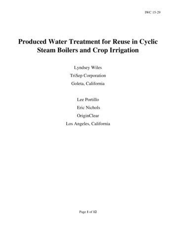
DWSS – Part 1Part 1 - Basics of Hydraulics11/02/2014Introduction to Basics of HydraulicsWhat you will learnThe hydraulics notions useful to design water supply system.WhyEnsure a basic and common understanding of the necessary theory to design watersupply system.Duration of the training15 to 30 hoursGenerality about this courseThis course is the first part of the Design of Water SupplySystem methodology.It makes the review of the important parts of hydraulicsnecessary to design WSS.It is aimed for engineers or technicians with goodunderstanding of water system.Nevertheless, as illustrated in the attached diagram, it doesnot yet explain how to design the main components of theWSS. This is done in the second part of the training with theexplanation on how to use several Excel tools to assist theengineer in his design.Methodology to design &implement a WSS project132The course is divided in 7 chapters, for each of them youhave a theoretical part to be study and some exercises tomake sure that the theory was well understood. Thecorrections of the exercises are also given, but it is importantto try to do the exercises without the solutions, and use themonly if you are blocked.Learn &understandhydraulicsAssessment,data acquisition&future users’ consultationConcept designAgreement &involvement of allpartiesIt is also divided in two levelsThe Basic level is the minimum requirement to have a basedunderstanding on the main principles covering the mainsituations, without going too much in to complicate equationsand special cases. The sub chapters to be done for this basiclevel are indicated by a star *.The Intermediate level is the remaining theory, going morein details in the theory and covering most of the situationencountered (low/high temperature, high elevation, flattenpipes, ect).4Detailed & constructiondesign5Work implementation6Operation &maintenance
DWSS – Part 1Ch1 - Properties of Fluids and PipesChapter 1.11/02/2014Properties of fluids and pipesWhat you will learnUnderstand the basic essentials of fluid properties.WhyIt is important to understand and master the characteristic behaviours of fluids,especially of water and of air. This lays the groundwork for an understanding ofhydrostatics and hydrodynamics - the following chapters of this course.Duration of chapter 11 to 2 hours1.1.Definition *A fluid is any substance which flows because its particles are not rigidly attached to one another.This includes all liquids, all gases and even some materials which are normally considered assolids, such as glass. Liquids are almost incompressible while gases are readily compressible;liquids occupy a more or less constant volume and have a surface, whereas gases can expandand contract to fully occupy an available volume.In hydraulics, water and air are the two main fluids of interest. Their main properties are describedbelow.1.2.Density *The density of a material is defined as the mass per unit volume. The SI units for density are kg/m3:ρ: density in kilos per cubic meter [kg/m3]m: mass in kilos [kg]V: volume in cubic metres [m3] mEq. 1-1VFor a gas, the density will vary a lot with pressure and temperature:P: absolute pressure [N/m2] or [Pa]R: gas constant, for dry air it is about 29.3 [m/K]T: temperature in Kelvin [K] (0 C 273.15 K)g: earth gravity (9.81 m/s2) PEq. 1-2R T gThis is a variation of the ideal gas law:P: is the absolute pressure [Pa]V: volume in cubic meter [m3]T: is the temperature in Kelvin [K]P V cte Eq. 1-3TThe density of a liquid does not vary significantly with temperature; for example, the density ofwater varies by 0.3% between 5 C and 25 C (see annexe). In comparison, the density of a gas willvary by 7% over the same temperature range.Relative density is defined as the ratio of the density of a substance to the density of a givenreference material. The reference material is usually water. For example the relative density ofmercury is 13.5 and for ethanol it is 0.789Ch1 - 1/6
DWSS – Part 11.3.Ch1 - Properties of Fluids and Pipes11/02/2014Young's and bulk modulusThe Young's modulus for solids and the bulk modulus for fluids (K)measure the resistance to uniform compression. It is defined as thepressure increase needed to cause a given relative decrease involume. Its base unit is the Pascal. P KΔVEq. 1-4V0Bulk modulus for somematerials K101 kPaAir(isotherm)Water2.0 - 2.3 GPaSteel160 - 200 GPaCast iron80 - 170 GPaConcrete30 - 50 GPaGlass35 - 55 GPaAsbestos23 - 24 GPaPE0.7 - 1.2 GPaPVC3 - 4.7 GPaThe following formula can be used to calculate the change in diameter of a pipedue to an increase in internal pressure ΔP:D: diameter of pipe [m]ΔD ΔP De: thickness of pipe [m] Eq. 1-5K: Bulk modulus of pipe [Pa]DK 2 eΔP: Pressure increase [Pa]The compressibility of water and pipes can be usually neglected in hydraulics for steady flows; it isless than 1% for maximum permissible pressures - this effect is overshadowed by the tolerancesused for pipe production.However, this is not the case for a transitional situation (water hammer), where compressibilityinfluences the speed and amplitude of a perturbation as it propagates through the pipes.1.4.ViscosityThe viscosity of a fluid is a measure of its resistance to a tangential force; this resistance is mainlycaused by interactions between the fluid's molecules.Consider two large parallel plates, close to each other (y is small) and separated by a given fluid.For the upper plate to move at a constant velocity, a force F should be applied. This force will beproportional to the surface area of the plates and to the velocity of the upper plate, and is inverselyproportional to the distance between the plates.vFA vF: force in Newton [N]F Eq. 1-6μ: dynamic viscosity [Pa·s]yA: Surface of the plates [m2]yF yv: velocity of the upper plate [m/s] Eq. 1-7y: distance between the plates [m]A vWhen the dynamic viscosity is independent of the shear stress (F/A), μ is constant (at a giventemperature) and the fluid is called Newtonian, this is the case for water and most gases.Kinematic viscosity ν, is a useful variable in hydraulics. It isdefined as the ratio of dynamic viscosity to density.It is expressed in [m2/s] or in Stokes [St].Ch1 - 2/6 Eq. 1-8
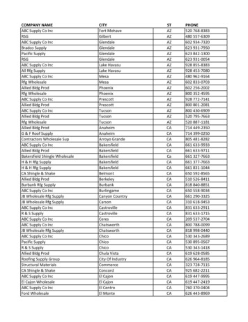
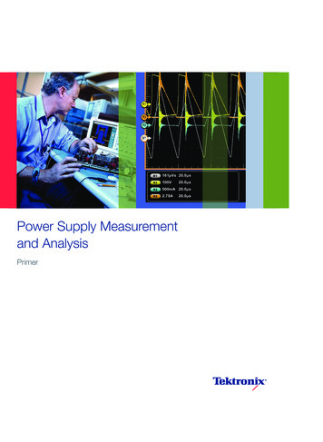
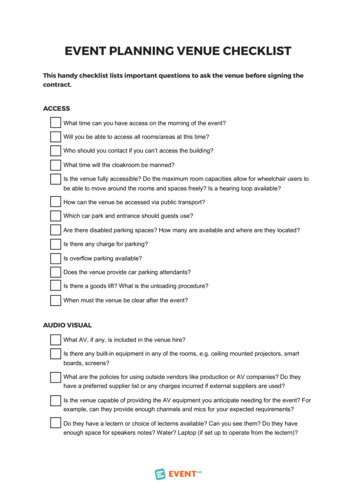
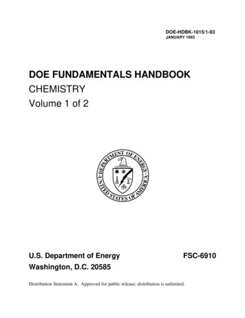
DWSS – Part 1Ch1 - Properties of Fluids and Pipes11/02/2014Kinematic viscosity [μm2/s]21.5ν 3.244 10-8 t4 - 9.02 10-6 t3 9.785 10-4 t2 - 5.485 10-2 t 1.77910.500102030405060708090100Temp [ C]Fig 1- 1 Water viscosity at different temperaturesAs shown in the chart, the viscosity decreases considerably as temperature increases. Forinstance, between 0 C and 20 C the viscosity of water decreases by 44%.1.5.Phase transformationsPhase transformations refer to changes in the physical state of matter. Elements and simplecompounds can generally exist as either solids, liquids or gases.For water (H2O), these states can be ice, liquid water and/or water vapour.The state of a material at a given moment depends on its composition and on the temperature andthe pressure exerted.For instance at sealevel ( 105 Pa), waterwill be ice below 0 C,liquid between 0 C and100 C,andwatervapour above 100 C.At a pressure of 611Pa, water will be solidice up to 0.1 C and willthen sublimate directlyto the vapour state.CriticalpointFreezingPressurePaNB: For a better understanding, the scales arenot onTriplepoint 611Thesestatesareoutlined for water in thisphase diagram. p CFig 1- 2 Phase diagram of waterCh1 - 3/6374
DWSS – Part 1Ch1 - Properties of Fluids and Pipes11/02/2014The triple point: The single combination of pressure and temperature at which liquid water, solidice, and water vapour can coexist in a stable equilibrium occurs at exactly 273.16 K (0.01 C) anda pressure of 611 Pa. At that point, it is possible to change all of the substance to ice, water, orvapour by making small changes in pressure or temperature.The critical point: The vapour-liquid critical point denotes the conditions abovewhich distinct liquid and gas phases do not exist. As the critical temperature isapproached, the properties of the gas and liquid phases approach one another,resulting in only one phase at the critical point: a homogeneous supercritical fluid.The heat of vaporization is zero at and beyond this critical point, so there is nodistinction between the two phases. Above the critical temperature a liquid cannotbe formed by an increase in pressure, but with enough pressure a solid may beformed. The critical pressure is the vapour pressure at the critical temperature.Note that when there is a mix of elements (like air & water) the situation becomes morecomplicated (which is why we have water vapour in the air below 100 C). This will be furtherdeveloped in the next chapter.Table 1 : Properties of waterTemp[ 2990.2988.11.792 10-61.519 10-61.308 10-61.141 10-61.007 10-60.897 10-60.804 10-60.727 10-60.661 10-60.605 10-60.556 10-61.6. ThermalDensityVapourBulkTempρPressure Modulus[ /s]0.556 10-60.513 10-60.477 10-60.444 10-60.415 10-60.390 10-60.367 10-60.347 10-60.328 10-60.311 10-60.296 .312.282.262.252.232.212.172.162.112.07expansion of pipesThe change in temperature does not only influence the properties of water (like density andviscosity) but also has impacts on the pipes, which will expand as the temperature rises. For somematerials, as for polyethylene, the dilatation effect can be non-negligible. With an increase intemperature, the pipe will increase its length as well as its diameter.ΔL:L:ΔT:αT:total elongation of the pipe [mm]length of the pipe before expansion [m]change in temperature [ K]thermal expansion coefficient [mm/m K]ΔL L ΔT α TCh1 - 4/6Eq. 1-9LΔL
DWSS – Part 1Ch1 - Properties of Fluids and PipesΔD: total increase in pipe's diameter [mm]D: (inside or outside) diameter of the pipebefore expansion [m]ΔT: change in temperature [ K]αT: thermal expansion coefficient [mm/m K]11/02/2014ΔD D ΔT α TEq. 1-10DD ΔDThermal expansioncoefficient of somematerials (mm/m K)PE0.200PVC0.080Steel0.011Cast iron0.012Glass0.009Concrete0.010Therefore, the main consequences of thermal expansion from ahydraulic point of view will be an increase of the cross-sectional forplastic pipes, which can influence the flow. The increase in head lossdue to the elongation of the pipe is negligible. In practice, theincrease in length will mainly matters when we deal with hot fluids,but it is not the purpose of this course.References for this ityhttp://en.wikipedia.org/wiki/Bulk modulusBooks:Série Schaum, Mécanique des fluides et hydraulique, Ranald V. GilesELBS, Fluid Mechanics 2nd edition, Douglas, Gasiorek, SwaffieldCh1 - 5/6
DWSS – Part 1Ch1 - Properties of Fluids and Pipes11/02/2014Basic exercises1. What is the mass of 1 dm3 of mercury?2. What is the density of sea water at 5 C knowing that the average salinity is 35 grams per litre?3. What is the density of air at a pressure of 105 Pa and 30 C?4. In a closed air tank we have a pressure of 10 105 Pa at 0 C. As the maximum pressureauthorised for the vessel is 12 105 Pa, what is the maximum temperature admissible?5. How does the density of water change with an increase in pressure (30 105 Pa) at constanttemperature (5 C)?Intermediary exercises6. What corresponding reduction in the volume of a 1m3 steel cube is caused by an increase of20 105 Pa?7. In what state does water exist at 5 105 Pa and 0 C?8. What will be the length and diameter of a PE pipe (original length 20m, original diameter100mm), after thermal expansion due to temperature changing from 5 C to 25 C?9. A plate 50 x 50 cm is supported by a water layer 1 mm thick. What force must be applied to thisplate so that it reaches a speed of 2m/s at 5 C and at 40 C?Advanced exercises10. When a PE pipe with an outside diameter of 200 mm is pressurized to 10 105 Pa, what are the% increases in diameter for pipe wall thicknesses of 9.1 mm, 14.7 mm, and 22.4 mm?11. On the following three dimensional (P,V,T) phase diagram for water, indicate the followingareas, lines or points: critical point (point) & triple point (line) liquid water (area); solid ice (area); water vapour (area); supercritical fluid (area) liquid water & solid ice (area); liquid water & water vapour (area); solid ice & watervapour (area)Ch1 - 6/6
DWSS – Part 1Chapter 2.Ch2 - Hydrostatics11/02/2014HydrostaticsWhat you will learnUnderstand and assimilate the principles of atmospheric pressure and water pressurein hydrostatics.WhyA solid understanding of the pressure characteristics for systems involving water at restis an essential requirement in order to understand hydrodynamics.Duration of chapter 21 to 2 hours2.1.Introduction *Hydrostatics is the study of the mechanical properties of fluids that are not in motion. In a watersupply system, this is assumed to be the situation at night, when there is no one using the supplyand leaks are insignificant/ignored. Water supply pipes are – and remain - under pressure.Hydrodynamics will take into account the movement of water through piping systems.Ch2 - 1/7
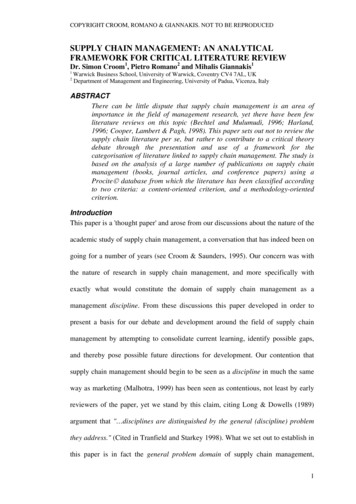
DWSS – Part 12.2.Ch2 - Hydrostatics11/02/2014Pressure *The pressure is the force per unit area applied in a direction perpendicular to the surface of anobject.P : Pressure in Pascal [N/m2]F: Force in Newton [N]A: Surface in square metres [m2]P FEq. 2-1AFAFollowing International System of Units, a pressure of 1 Pascal is created by applying a force of 1Newton (the force applied by 100g) acting on a plate of 1 square metre. If the same force is appliedon a half square meter plate, the pressure will be doubled (2 Pa). Since a Pascal is quite a smallunit, common multiples are more frequently used in practice, as given in the following table.The pressure exerted by a liquid on a surface is directly proportional to its weight; therefore itcannot be negative. Similarly, the pressure exerted by a gas is a function of the impact of itsparticles against a surface (i.e. a function of its mass and temperature); therefore it cannot benegative.Different units used for pressure :1 Pa1 bar1 atm1 Torr1 psiPascal(Pa)Bar(bar)Atmosphere(atm) 1 N/m2100'000101'325133.3226.894 10310 5 10 N/cm21.013251.3332 10 368.948 10 39.8692 10 60.98692 1 atm1.3158 10 368.046 10 3torr(Torr)7.5006 10 3750.06760 1 mmHg51.715Pound-force persquare inch(psi)145.04 10 614.503774414.69619.337 10 3 1 lbf/in2The hecto Pascal (hPa) is the unit used in meteorology (1 hPa 100 Pa)2.3.Atmospheric pressureAtmospheric pressure is the force exerted by the weight of air in the Earth's atmosphere. Theaverage pressure at sea level is arbitrarily defined as 1 standard atmosphere (symbol: atm) whichis equivalent to 101'325 Pa. An air column of ten square centimetres in cross-section, measuredfrom sea level to the top of the atmosphere, weighs approximately 103.3 Kg.Atmospheric pressurenuit1535varies at a given point1530with the local conditions,1525(temperature of air,1520humidity, wind, moon1515and sun, etc).15101505In the tropics, significantdiurnal pressure cyclesare observed, this effectisknownasatmospheric 15:0012:0009:001475Fig 2- 1 Cyclic variations in atmospheric pressure over two days in GomaCh2 - 2/7
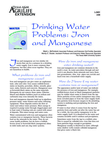
DWSS – Part 1containerCh2 - HydrostaticsVacuumh VacuumPaEq. 2-2 gh: height of the liquid columnPa : atmospheric pressure : density of the liquidg : acceleration due to gravityA : Section of the tubehPaMercury (Hg)11/02/2014Mercury (Hg)Fig 1Fig 2When there is no gas (vacuum) in a container, there is no pressure. If we dip the bottom of a testtube in a bowl of mercury in a complete vacuum, the level of the mercury will remain at the samelevel inside the tube and in the bowl (fig 1). If air is then allowed to enter the container, it will pushdown on the surface of the mercury in the bowl and a column will rise inside the tube until theweight of this column counterbalances the air pressure.To calculate the height of this column, the force dueto the air pressure equals the force due to the weightof the mercury column:FHg m Hg g ρHg VHg g ρHg h A gFa Pa AFa FHg Pa ρ h gAs elevation increases there is less atmospheric mass, so atmospheric pressure decreases withincreasing elevation. A simplified relationship (not taking temperature differences into account) isshown graphically. 0.0065 h P h 101325 1 288.15 P : Mean atmospheric pressure [Pa]h : Altitude [m]In such cases, it might be necessary totakeatmosphericpressureintoconsideration for system design. Min andmax pressure depend on location butcan be estimated at a first stage at -41 to 31 hPa from average pressure.The P min has to be used for design, asit is the most critical case.2.4.Eq. 2-31100Atmospheric pressure [hPa]In this graph, we can see that at 1'000 mabove sea level (masl), the meanatmospheric pressure is about 900 hPa(11% less than at sea level); and 750hPa at 2'500 masl, corresponding to thealtitudes in Asmara or Addis Ababa,(25% less than at sea level).5.2551000P maxP averageP min900800700600500010002000300040005000Altitude [m]Fig 2- 2 Variation of pressure with altitudeVapour pressureThe vapour pressure is the pressure at which water will vaporise (pass from liquid to vapour). Forinstance, at a fixed pressure of 1013 hPa (1atm), water will start to boil at 100 C and it will remainat this temperature until it is completely vaporised.Ch2 - 3/7
DWSS – Part 1Ch2 - Hydrostatics11/02/2014At a constant 20 C, water remains liquid above 24 hPa. However, if the system pressure fallsbelow this threshold, the water will start to vaporise, producing cavitation (constant temperature,decrease of pressure).AirPVVacuumVapourVapourhPVWater (H2O)PaPVWater (H2O)Water (H2O)Fig 1Fig 2Fig 3If water at 20 C is placed in a bowl in a container under vacuum (fig 1), as the pressure is very low,it will evaporate until the vapour pressure is reached in the container (fig 2). It will then be in aphase equilibrium with two phases, water vapour and liquid water at a pressure of 24 hPa.If the temperature rises, more water will evaporate and the pressure will rise. If the temperaturedecreases, the vapour will condense and the pressure will decrease.If air at atmospheric pressure is allowed to enter the container (fig 3), a water column will rise in thetube until the column weight balances the pressure differences. While the PV in the container willbe included (not added) in the Pa, the Pv in the tube will remain.In this case, on top of the weight of the water column, you have thevapour pressure, balancing the atmospheric pressure, thereforethe Eq 2-2 becomes:Thus when the temperature rises it will decrease the water columnheight and when it reaches the boiling point, PV Pa, the height ofthe column is zero.h Pa - PVEq. 2-4 gThis h gives also the maximum height to which a column of water can be raised or pumped. It willbe about 10 m at 25 C at sea level, but will decrease to about 7.3 m for the same temperature at2500 m above sea level. For higher temperatures it will decrease quickly, therefore pumping hotwater has to be carefully done.1'000500Vapour Pressure200Fig 2- 3Vapourpressure inhPaaccordingtotemperature10050hPa20Pv 9.42 10-6 t4 - 2.91 10-4 t3 0.0331 t2 0.242 t 6.1110501020304050T CCh2 - 4/760708090100
DWSS – Part 12.5.Ch2 - Hydrostatics11/02/2014Relative Water pressure *The total pressure in the water will be composed of the atmospheric pressure exerted at thesurface of the water plus the pressure due to the water column.Ptot: Total pressure [Pa]Pa: Atmospheric pressure [Pa]ρ: water density [kg/m3]g: is the earth's gravity [m/s2]h: depth of water [m]Ptot Pa Pwater Pa g hEq. 2-5But if we look at the bottom or at the side of a water tank, the atmospheric pressure will actperpendicular to the surface, counterbalancing the effect of the pressure of the surface of thewater. Thus the pressure on the side and the bottom of a tank will mainly be affected by the depth(h) of water.Similarly, when we look at the pressure at the top of a pipe and at the bottom, both are subject toalmost the same atmospheric pressure, therefore the available pressure will be the pressure due tothe difference of water height.PaPbottom Ptot Pa Pa g h PaPbottom g hEq. 2-6Pbottom 10'000 hPaPaPa PwaterhPaThis is why in hydraulics, the pressure (P) refers to the water pressure and not to the totalpressure. This is also why the pressure can under certain conditions be lower than 0 Pa.For practical reasons, the units used are the bar or the meter of water column: 1 bar 10 mWCIn a water supply system, pressure can be efficiently created by elevated tanks placed at a highposition. In the following figures the static pressure provided by the elevated tank is 40 mWC or4 bar40 mWCFor house delivery, it is usual to have a pressure ranging from 3 to 5 bars.Ch2 - 5/7
DWSS – Part 1Ch2 - Hydrostatics2 bar2 bar11/02/20142 bar2 barThe pressure at the bottom of a reservoir is independent of its shape; for the same liquid level(height), the pressure at the bottom will be the same. This is important b
The hydraulics notions useful to design water supply system. Why Ensure a basic and common understanding of the necessary theory to design water supply system. Duration of the training 15 to 30 hours Generality about this course This course is the first part of the Design